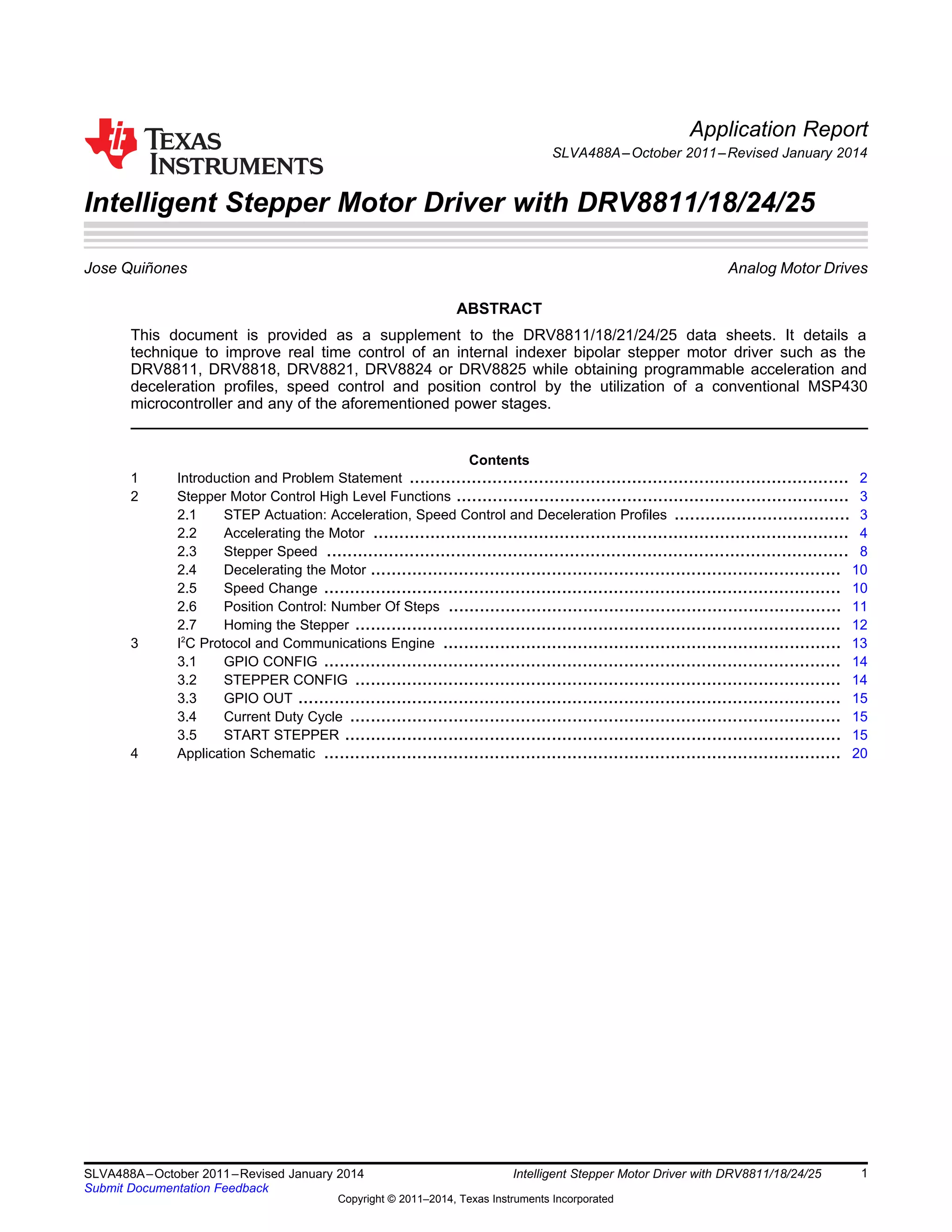
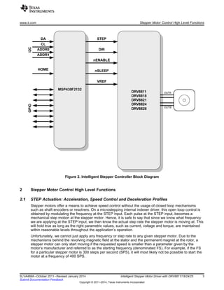
This document provides a technique for improving real-time control of an internal indexer bipolar stepper motor driver like the DRV8811/18/21/24/25. It details how to implement programmable acceleration and deceleration profiles, speed control, and position control using a microcontroller like the MSP430. The technique uses the microcontroller to send control signals to the motor driver over an I2C interface to control the stepper motor's speed, position, acceleration, and deceleration in a precise manner.

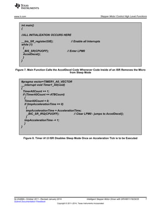
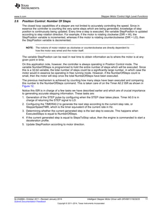
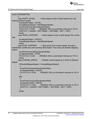
![#pragma vector=TIMER0_A1_VECTOR
__interrupt void Timer0_A1(void)
{
switch (TA0IV)
{
case TA0CCR1_CCIFG_SET:
break;
case TA0CCR2_CCIFG_SET:
TA0CCR0 = TA0CCR2 + StepPulseWidth; //2 us at 16 MHz
TA0CCR2 += StepperSpeedTMR;
ExecutedSteps += 1;
if (ExecutedSteps == NumberOfSteps)
{
TA0CCTL2 &= ~(CCIE + BIT5 + BIT6 + BIT7); //Disable Pulse Generation
}
else if (ExecutedSteps == StepsToStop)
{
AccelTimeCompute(DecelerationRate);
AccelerationState = STOP;
TA1CCTL0 |= CCIE; //ENABLE 250 us coordinator interrupt on TA1.0
}
if (P3IN && DIR)
{
StepPosition += 1;
}
else
{
StepPosition -=1;
}
ReadTable[0] = (StepPosition & 0xFF00) >> 8;
ReadTable[1] = StepPosition & 0xFF;
break;
case TA0IFG_SET:
break;
}
}
Stepper Motor Control High Level Functions www.ti.com
Figure 12. Timer A0.2 ISR
2.7 Homing the Stepper
The concept of preserving stepper position is in essence flawed if we do not know the system’s start
position. This is true for any motor system in which the closed loop feedback is relative, versus absolute.
As a result, it is important we start counting our steps from a known position. Said position is often
referred to as HOME.
The application note incorporates a HOME sensor input which is flexible enough to accommodate both
sensor polarities (e.g. asserted HI or asserted LO). A typical HOME sensor implementation is to have an
optical sensor and a flag at the stepper motor shaft. When the flag meets the optical sensor slit, then the
stepper motor stops and this position is from now on referred to as HOME. Internally, the controller clears
the StepPosition variable.
12 Intelligent Stepper Motor Driver with DRV8811/18/24/25 SLVA488A–October 2011–Revised January 2014
Submit Documentation Feedback
Copyright © 2011–2014, Texas Instruments Incorporated](https://image.slidesharecdn.com/stepperydrv8811-140809170013-phpapp02/85/Stepper-y-drv8811-12-320.jpg)
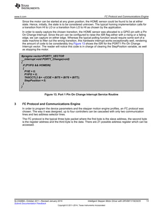
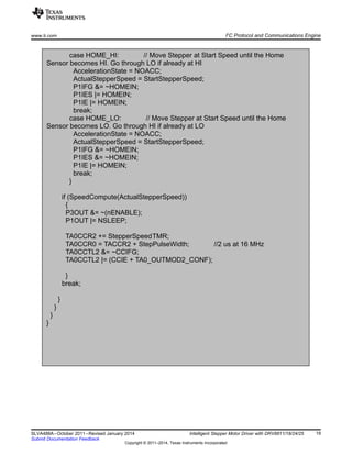
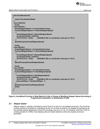
![#pragma vector=USCIAB0TX_VECTOR //UCA_TRANSMIT on UART/SPI;
UCB_RECEIVE, UCB_TRANSMIT on I2C
__interrupt void USCI_AB0_Transmit(void)
{
if (UCB0CTL1 & UCTR)
{
UCB0CTL1 &= ~UCTR;
IFG2 &= ~UCB0TXIFG;
}
else
{
SerialBuffer[SerialPointer] = UCB0RXBUF;
SerialPointer += 1;
if (SerialPointer == SERIAL_BUFFER_LENGTH)
{
SerialPointer = 0;
ParametersTable[ADDRESS] = PARAMETER;
switch(ADDRESS)
{
case GPIO_CONFIG:
char tempOut;
P1DIR = PARAMETER & 0xC0; //Use 2 MSB's to configure the
GPIO Direction on pins P1.7 and P1.6
P2DIR = PARAMETER & 0x3F; //Use 6 LSB's to configure the
GPIO direction on pins P2.0 to P2.5
case STEPPER_CONFIG_ADDR:
tempOut = P3OUT;
tempOut &= ~(nENABLE + MODE0 + MODE1 + MODE2 + DIR);
tempOut |= PARAMETER;
P3OUT = tempOut; break;
case GPIO_OUT_ADDR:
P2OUT = PARAMETER;
tempOut = P1OUT;
tempOut &= ~(BIT7 + BIT6);
tempOut |= (PARAMETER & 0xC0);
P1OUT = tempOut;
break;
case CURRENT_DC_ADDR:
TA1CCR1 = PARAMETER;
break;
I2
C Protocol and Communications Engine www.ti.com
16 Intelligent Stepper Motor Driver with DRV8811/18/24/25 SLVA488A–October 2011–Revised January 2014
Submit Documentation Feedback
Copyright © 2011–2014, Texas Instruments Incorporated](https://image.slidesharecdn.com/stepperydrv8811-140809170013-phpapp02/85/Stepper-y-drv8811-16-320.jpg)
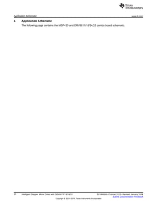
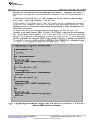
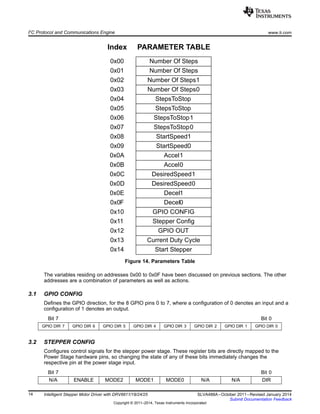
![case START_STEPPER_ADDR:
NumberOfSteps = (ParametersTable[NUMBER_OF_STEPS3_ADDR] << 8) +
(ParametersTable[NUMBER_OF_STEPS2_ADDR]);
NumberOfSteps *= 65536;
NumberOfSteps += (ParametersTable[NUMBER_OF_STEPS1_ADDR] << 8) +
ParametersTable[NUMBER_OF_STEPS0_ADDR];
ExecutedSteps = 0;
StepsToStop = (ParametersTable[STEPS_TO_STOP3_ADDR] << 8) +
(ParametersTable[STEPS_TO_STOP2_ADDR]);
StepsToStop *= 65536;
StepsToStop += (ParametersTable[STEPS_TO_STOP1_ADDR] << 8) +
ParametersTable[STEPS_TO_STOP0_ADDR];
StartStepperSpeed = (ParametersTable[START_SPEED1_ADDR] << 8) +
ParametersTable[START_SPEED0_ADDR];
DesiredStepperSpeed = (ParametersTable[DESIRED_SPEED1_ADDR] << 8) +
ParametersTable[DESIRED_SPEED0_ADDR];
AccelerationRate = (ParametersTable[ACCEL1_ADDR] << 8) +
ParametersTable[ACCEL0_ADDR];
DecelerationRate = (ParametersTable[DECEL1_ADDR] << 8) +
ParametersTable[DECEL0_ADDR];
www.ti.com I2
C Protocol and Communications Engine
17SLVA488A–October 2011–Revised January 2014 Intelligent Stepper Motor Driver with DRV8811/18/24/25
Submit Documentation Feedback
Copyright © 2011–2014, Texas Instruments Incorporated](https://image.slidesharecdn.com/stepperydrv8811-140809170013-phpapp02/85/Stepper-y-drv8811-17-320.jpg)