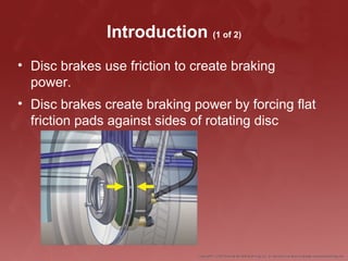
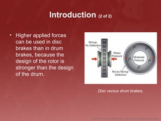
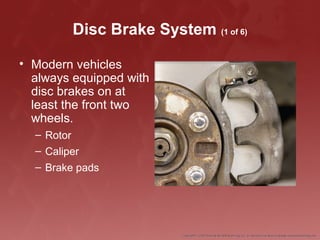
Disc Brake System
Introduction (1 of 2)
• Disc brakes use friction to create braking
power.
• Disc brakes create braking power by forcing flat
friction pads against sides of rotating disc
Introduction (2 of 2)
• Higher applied forces
can be used in disc
brakes than in drum
brakes, because the
design of the rotor is
stronger than the design
of the drum.
Disc versus drum brakes.
Disc Brake System (1 of 6)
• Modern vehicles
always equipped with
disc brakes on at
least the front two
wheels.
– Rotor
– Caliper
– Brake pads
Disc Brake System (2 of 6)
• Pushrods transfer
force through brake
booster.
• Master cylinder
converts pedal force
to hydraulic pressure.
Disc Brake System (3 of 6)
• Hydraulic pressure
transmitted via brake lines
and hoses to piston(s) at
each brake caliper.
• Pistons operate on friction
pads to provide clamping
force
• Rotors are free to rotate due
to wheel bearings and hubs
that contain them
• Hub can be part of brake
rotor or separate assembly
that the rotor slips over and
is bolted to by the lug nuts
The hub and hubless rotors.
Disc Brake System (4 of 6)
• The brake caliper
assembly is normally
bolted to the vehicle
axle housing or
suspension
Caliper mounting methods.
Disc Brake System (5 of 6)
• Advantages
– Greater amounts of heat to atmosphere
– Cooling more rapid
– Rotors scrape off water more efficiently
– Self-adjusting
– Don’t need periodic maintenance
– Easier to service
Disc Brake System (6 of 6)
• Disadvantages
– Prone to noise (squeals and squeaks)
– Rotors warp easier
– Not self-energizing
– Hard to use as parking brakes
Disc Brake Calipers (1 of 11)
• Bolted to vehicle axle
housing (steering
knuckle)
• Two types of calipers:
fixed and
sliding/floating
Disc Brake Calipers (2 of 11)
Fixed calipers with multiple
pistons.
Fixed caliper being applied.
Disc Brake Calipers (3 of 11)
• When the brakes are
applied, hydraulic
pressure forces the
piston toward the rotor.
– Takes up any clearance
– Pushes pad into rotor
• Once all clearance is
taken up on outer brake
pad, clamping force will
increase equally on both
brake pads, applying
brakes.
Sliding/floating caliper application.
Disc Brake Calipers (4 of 11)
O-rings. A. Square cut O-ring and O-ring cut to show square section.
B. Square cut O-ring groove in caliper.
Disc Brake Calipers (5 of 11)
• Square cut O-ring seals piston in disc brake
calipers.
– Compressed between piston and caliper housing
– Keeps high-pressure brake fluid from leaking
– Prevents air from being drawn into system
Disc Brake Calipers (6 of 11)
Square cut O-ring. A. Square cut O-ring during brake application.
B. Square cut O-ring during brake release.
Disc Brake Calipers (7 of 11)
• Low-drag calipers
designed to maintain
larger brake pad-to-
rotor clearance.
Disc Brake Calipers (8 of 11)
• Although the phenolic
pistons themselves
do not corrode, the
cast iron bore of the
caliper does corrode
and rust
– can cause a phenolic
piston to seize in the
bore
Disc Brake Calipers (9 of 11)
• Phenolic pistons
transfer heat slower
than steel pistons
– Helps prevent
boiling of the brake
fluid
Heat transfer. A. Phenolic piston (slow
heat transfer). B. Steel piston (fast
heat transfer).
Disc Brake Calipers (10 of 11)
• Bushings must be
lubricated with high-
temperature,
waterproof disc brake
caliper grease.
• Floating calipers are
mounted in place by
guide pins and
bushings
Disc Brake Calipers (11 of 11)
• Sliding calipers slide
in the caliper mount
and are held in place
by a spring steel clip.
Disc Brake Pads and Friction
Materials (1 of 11)
• Disc brake pads consist of friction material
bonded or riveted onto steel backing plates.
Disc Brake Pads and Friction
Materials (2 of 11)
• Backing plate has lugs
that correctly position the
pad in the caliper
assembly and help the
backing plate maintain
the proper position to the
rotor
Brake pad locating lugs.
Disc Brake Pads and Friction
Materials (3 of 11)
• Amount of friction expressed as ratio
– Coefficient of friction
• Kinetic energy (motion) of sliding surfaces
converts to thermal energy (heat).
Disc Brake Pads and Friction
Materials (4 of 11)
• Composition of friction
material affects brake
operation
– Materials that provide good
braking with low pedal
pressures tend to lose
efficiency when hot
• Wear out quicker
– Materials that maintain stable
friction coefficient over a wide
temperature range
• Generally require higher
pedal pressures
• Tend to put added wear
on disc brake rotor
Disc Brake Pads and Friction
Materials (5 of 11)
• Disc brake pads and drum brake linings are
made from materials that have a moderate
coefficient of friction.
Disc Brake Pads and Friction
Materials (6 of 11)
• Brake friction materials:
– NAO materials
– Low-metallic non-asbestos organic (NAO)
– Semimetallic materials
– Ceramic materials
Disc Brake Pads and Friction
Materials (7 of 11)
• Combination of weighted qualities:
– Stopping power
– Heat absorption and dispersion
– Resistance to fade
– Recovery speed from fade
– Wear rate
– Performance when wet
– Operating noise
– Price
Disc Brake Pads and Friction
Materials (8 of 11)
• Coefficients of
friction:
– C: ≤0.15
– D: 0.15–0.25
– E: 0.25–0.35
– F: 0.35–0.45
– G: 0.45–0.55
– H: >0.55
– Z: Unclassified
Disc Brake Pads and Friction
Materials (9 of 11)
• Disc brakes more prone to squealing
– Due to vibrations between brake pad and rotor
– Shims and spring-loaded clips help reduce
squealing.
Disc Brake Pads and Friction
Materials (10 of 11)
• Anti-noise measures:
– Softer linings
– Brake pad shims
– Springs to hold in
place
Example of brake pad retainers.

Details About Brake Rotors Systems

  • 1.
  • 2.
    Introduction (1 of2) • Disc brakes use friction to create braking power. • Disc brakes create braking power by forcing flat friction pads against sides of rotating disc
  • 3.
    Introduction (2 of2) • Higher applied forces can be used in disc brakes than in drum brakes, because the design of the rotor is stronger than the design of the drum. Disc versus drum brakes.
  • 4.
    Disc Brake System(1 of 6) • Modern vehicles always equipped with disc brakes on at least the front two wheels. – Rotor – Caliper – Brake pads
  • 5.
    Disc Brake System(2 of 6) • Pushrods transfer force through brake booster. • Master cylinder converts pedal force to hydraulic pressure.
  • 6.
    Disc Brake System(3 of 6) • Hydraulic pressure transmitted via brake lines and hoses to piston(s) at each brake caliper. • Pistons operate on friction pads to provide clamping force • Rotors are free to rotate due to wheel bearings and hubs that contain them • Hub can be part of brake rotor or separate assembly that the rotor slips over and is bolted to by the lug nuts The hub and hubless rotors.
  • 7.
    Disc Brake System(4 of 6) • The brake caliper assembly is normally bolted to the vehicle axle housing or suspension Caliper mounting methods.
  • 8.
    Disc Brake System(5 of 6) • Advantages – Greater amounts of heat to atmosphere – Cooling more rapid – Rotors scrape off water more efficiently – Self-adjusting – Don’t need periodic maintenance – Easier to service
  • 9.
    Disc Brake System(6 of 6) • Disadvantages – Prone to noise (squeals and squeaks) – Rotors warp easier – Not self-energizing – Hard to use as parking brakes
  • 10.
    Disc Brake Calipers(1 of 11) • Bolted to vehicle axle housing (steering knuckle) • Two types of calipers: fixed and sliding/floating
  • 11.
    Disc Brake Calipers(2 of 11) Fixed calipers with multiple pistons. Fixed caliper being applied.
  • 12.
    Disc Brake Calipers(3 of 11) • When the brakes are applied, hydraulic pressure forces the piston toward the rotor. – Takes up any clearance – Pushes pad into rotor • Once all clearance is taken up on outer brake pad, clamping force will increase equally on both brake pads, applying brakes. Sliding/floating caliper application.
  • 13.
    Disc Brake Calipers(4 of 11) O-rings. A. Square cut O-ring and O-ring cut to show square section. B. Square cut O-ring groove in caliper.
  • 14.
    Disc Brake Calipers(5 of 11) • Square cut O-ring seals piston in disc brake calipers. – Compressed between piston and caliper housing – Keeps high-pressure brake fluid from leaking – Prevents air from being drawn into system
  • 15.
    Disc Brake Calipers(6 of 11) Square cut O-ring. A. Square cut O-ring during brake application. B. Square cut O-ring during brake release.
  • 16.
    Disc Brake Calipers(7 of 11) • Low-drag calipers designed to maintain larger brake pad-to- rotor clearance.
  • 17.
    Disc Brake Calipers(8 of 11) • Although the phenolic pistons themselves do not corrode, the cast iron bore of the caliper does corrode and rust – can cause a phenolic piston to seize in the bore
  • 18.
    Disc Brake Calipers(9 of 11) • Phenolic pistons transfer heat slower than steel pistons – Helps prevent boiling of the brake fluid Heat transfer. A. Phenolic piston (slow heat transfer). B. Steel piston (fast heat transfer).
  • 19.
    Disc Brake Calipers(10 of 11) • Bushings must be lubricated with high- temperature, waterproof disc brake caliper grease. • Floating calipers are mounted in place by guide pins and bushings
  • 20.
    Disc Brake Calipers(11 of 11) • Sliding calipers slide in the caliper mount and are held in place by a spring steel clip.
  • 21.
    Disc Brake Padsand Friction Materials (1 of 11) • Disc brake pads consist of friction material bonded or riveted onto steel backing plates.
  • 22.
    Disc Brake Padsand Friction Materials (2 of 11) • Backing plate has lugs that correctly position the pad in the caliper assembly and help the backing plate maintain the proper position to the rotor Brake pad locating lugs.
  • 23.
    Disc Brake Padsand Friction Materials (3 of 11) • Amount of friction expressed as ratio – Coefficient of friction • Kinetic energy (motion) of sliding surfaces converts to thermal energy (heat).
  • 24.
    Disc Brake Padsand Friction Materials (4 of 11) • Composition of friction material affects brake operation – Materials that provide good braking with low pedal pressures tend to lose efficiency when hot • Wear out quicker – Materials that maintain stable friction coefficient over a wide temperature range • Generally require higher pedal pressures • Tend to put added wear on disc brake rotor
  • 25.
    Disc Brake Padsand Friction Materials (5 of 11) • Disc brake pads and drum brake linings are made from materials that have a moderate coefficient of friction.
  • 26.
    Disc Brake Padsand Friction Materials (6 of 11) • Brake friction materials: – NAO materials – Low-metallic non-asbestos organic (NAO) – Semimetallic materials – Ceramic materials
  • 27.
    Disc Brake Padsand Friction Materials (7 of 11) • Combination of weighted qualities: – Stopping power – Heat absorption and dispersion – Resistance to fade – Recovery speed from fade – Wear rate – Performance when wet – Operating noise – Price
  • 28.
    Disc Brake Padsand Friction Materials (8 of 11) • Coefficients of friction: – C: ≤0.15 – D: 0.15–0.25 – E: 0.25–0.35 – F: 0.35–0.45 – G: 0.45–0.55 – H: >0.55 – Z: Unclassified
  • 29.
    Disc Brake Padsand Friction Materials (9 of 11) • Disc brakes more prone to squealing – Due to vibrations between brake pad and rotor – Shims and spring-loaded clips help reduce squealing.
  • 30.
    Disc Brake Padsand Friction Materials (10 of 11) • Anti-noise measures: – Softer linings – Brake pad shims – Springs to hold in place Example of brake pad retainers.