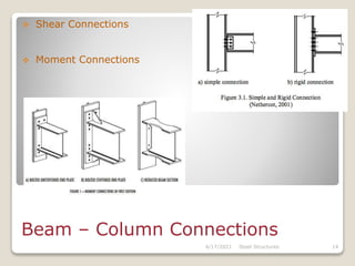
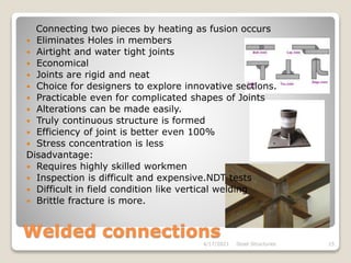
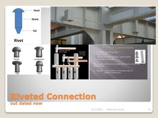
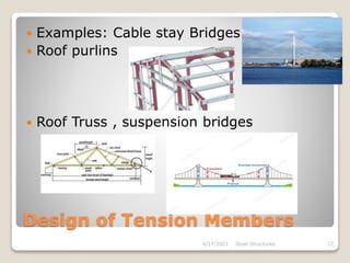
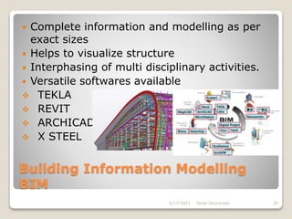
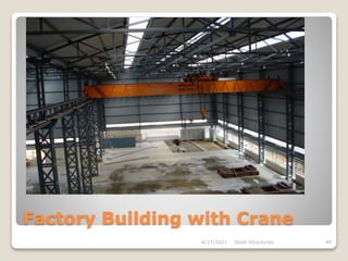
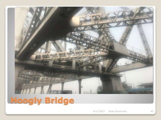
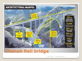
Steel Structures
Design, Detailing , Fabrication and Erection
Er. RAVINDRANATH B. V
ravibontadka@gmail.com
Steel Buildings
Introduction
Materials, specifications
Basis of Structural design
Connections: Bolted /Rivetted; Welded
Design of Members: Tension;
Compression; Beams: plate girders;
gantry girders; Beam-column; Industrial
Buildings; Torsion
4/17/2021 Steel Structures 2
Introduction
 Principal Building materials
Masonry
RCC and PSC
Structural steel
Wood
Others: FRP,
Aluminum,
Composites
4/17/2021 Steel Structures 3
Structural Steel
 Historical usage since 3000BC
 Ashokan pillar during Gupta period 1500 old
 First Cast iron Bridge in 1779 over river siren
 C I was used till 1840
 Wrought iron was introduced.
 Steel introduced in 1740 and commercially
patented in 1855.
 More usage in RCC and Buildings.
 During industrial revolution, it became more
prominent
4/17/2021 Steel Structures 4
Steel industry
 Iron Making
 Steel making ; integrated steel plants: mini
steel plants
 Major steel plants :
 Indian Consume 33kg/per/year: 300-500 in
dev. Countries: 220 in china
 Production – 108.5MioMT
 Designation; Fe310, Fe410WA, Fe540B
Fe- Steel: no is Characteristic UTS in MPA, W
denotes weldable: Grade A – IS 2062 :
general appl.Gr B – brittle fracture(bridges);
Gr C – low temp and impact
4/17/2021 Steel Structures 5
Steel members
Advantages
 Stress Strain curve- Follow Hooke’s Law -E
 Fire resistance, hardness, ductility
 Structural steel Products
 Hot rolled sections and plates
 Angle, channels, I section, T sections,
Plates, strips, Flats, square bars,
Round bars, Tubes - hot Rolled
 Cold Rolled : Channels, Zeds, angles,
hat sections, sigma sections
 Hollow steel sections: RHS,SHS,Round
 Welded Hybrid sections; Built up :
castellated beams
4/17/2021 Steel Structures 6
Advantages
 High strength : strength/wt ratio 3.5 times efficient
than concrete
 High ductility , uniformity
 Environment friendly : >400MioT recycled
i.e, 50% of steel produced
 Versatile : formed to different shapes and rolled to
variety of shapes and sizes
 Prefabrication: factory made, better Quality control,
least site work, proper planning
 Permanence: well maintained lasts long
 Easily modifiable; Addition alteration easy
 Fracture toughness: can be bent hammered, sheared,
holed..
 Elasticity: Behaves close to design assumption
4/17/2021 Steel Structures 7
Disadvantages
 Maintenance Costs
Fireproofing Costs- Strength reduces in high temp
Susceptibility to buckling
Fatigue.
4/17/2021 Steel Structures 8
Basis of Structural design
 Type of structure: Habitat -Framed, Shell, Tensile,
Pneumatic Str,: Non habitat- Bridges, Towers, Chimneys
 Connections; Simple, rigid, semi rigid, Mixed ,
composite , staggered lattice girder…
 Loads : gravity load, imposed loads, Wind loads,
seismic loads, Snow loads, erection loads, crane
loads, temp. effects
 Design Philosophies: Working stress: Ultimate
stress method: Limit state method
 Structural analysis: First order elastic: Second
order elastic: linear buckling: Inelastic buckling: First
order plastic: second order plastic
4/17/2021 Steel Structures 9
IS Codes and handbooks
 IS 875 : part 1- gravity loads: Part2 live
loads:
Part 3 – wind loads: Part 4 snow loads:
Part 5 – Special loads and combinations:
 IS 1893 (Part 1) – Earthquake loads
 IS 800 – General Steel Construction
 IS808- Hot rolled sections
 IS 802- OH towers
 IS 806- Steel Tubes
 SP6 (1)- Handbook for str. Steel sections
 Others ….
4/17/2021 Steel Structures 10
Design Philosophies
Working stress method : Factor of safety
Ultimate load design : Load factors
Limit state design : ultimate (safety) limit
state & Serviceability limit state
- partial safety factors for strength and serviceability
various loads and load combinations
Characteristic strength – yield strength with 95%pass
 Structural Stability – General Stability, Over turning
and Sway
 Deflection- limits for various elements
4/17/2021 Steel Structures 11
Grade of bolts – 3.6, 4.6,4.8,5.6,5.8 etc
Size of bolts – M5- M36
Black Bolts – C grade bolts IS 1363
HSFG Blots – IS 3757 & IS4000
Advantages:
unskilled labour and simple tools
Noiseless and simple fabrication
No special equipment or process is needed
Connection is thru after tightening
Bolted Connections
4/17/2021 Steel Structures 12
Types of Connections
 Concentric Connections
 Moment connections
Beam – Column Connections
 Shear Connections
 Moment Connections
4/17/2021 Steel Structures 14
Welded connections
4/17/2021 Steel Structures 15
Connecting two pieces by heating as fusion occurs
 Eliminates Holes in members
 Airtight and water tight joints
 Economical
 Joints are rigid and neat
 Choice for designers to explore innovative sections.
 Practicable even for complicated shapes of Joints
 Alterations can be made easily.
 Truly continuous structure is formed
 Efficiency of joint is better even 100%
 Stress concentration is less
Disadvantage:
 Requires highly skilled workmen
 Inspection is difficult and expensive.NDT tests
 Difficult in field condition like vertical welding
 Brittle fracture is more.
Riveted Connection
out dated now
4/17/2021 Steel Structures 16
Design of Tension Members
 Examples: Cable stay Bridges
 Roof purlins
 Roof Truss , suspension bridges
4/17/2021 Steel Structures 17
Design of tension members
Failure Mechanism
 GROSS SECTION YIELDING FAILURE
 NET SECTION RUPTURE FAILURE
 BLOCK SHEAR FAILURE
4/17/2021 Steel Structures 18
Design of Compression Members
Short Column – effective length
4/17/2021 Steel Structures 19
COMPRESSION MEMBERS
 VERY SHORT COLUMNS SUBJECTED TO
AXIAL COMPRESSION FAIL BY YIELDING
OR CRUSHING
 VERY LONG COLUMNS FAIL BY ELASTIC
BUCKLING IN THE EULER MODE
 INTERMEDIATE COLUMNS GENERALLY
FAIL BY INELASTIC BUCKLING
4/17/2021 Steel Structures 20
Euler’s Buckling Theory
Slender Columns buckling
4/17/2021 Steel Structures 21
Lateral Buckling
When Span to depth is large
4/17/2021 Steel Structures 22
Design of Flexure Members
 Types of Beam Sections
 Section Properties
4/17/2021 Steel Structures 23
Section Classification
 CLASSIFICATION OF SECTIONS
 PLASTIC
 COMPACT
 SEMI-COMPACT
 SLENDER
4/17/2021 Steel Structures 24
FACTORS EFFECTING BENDING
STRENGTH
 LATERALLY SUPPORTED
 LATERALLY UNSUPPORTED
4/17/2021 Steel Structures 25
FAILURES OF FLEXURE MEMBERS
 WEB BUCKLING
 WEB CRIPPLING
 DEFLECTION
4/17/2021 Steel Structures 26
ELEMENTS OF PLATE GIRDER
4/17/2021 Steel Structures 27
ELEMENTS OF PLATE GIRDER
 STIFFENERS:
 ➢ Vertical stiffeners
 ➢ Horizontal or longitudinal stiffeners
 ➢ Load bearing stiffeners
 ➢ End bearing stiffeners
 SPLICES:
 ➢ Flange splice
 ➢ Web splice
4/17/2021 Steel Structures 28
FABRICATION DRAWING &
DETAILING
 Very important to transform design ideas
to reality
 Should be self explanatory and clear
 Should Contain Junction details.
 To take into account Erection methods too
4/17/2021 Steel Structures 29
Detailing of Steel Structures
4/17/2021 Steel Structures 30
Detailing of truss 4/17/2021 Steel Structures 31
Detailing of Weld joints
4/17/2021 Steel Structures 32
Weld joints Detailing
4/17/2021 Steel Structures 33
Bill of Materials
4/17/2021 Steel Structures 34
Building Information Modelling
BIM
 Complete information and modelling as per
exact sizes
 Helps to visualize structure
 Interphasing of multi disciplinary activities.
 Versatile softwares available
 TEKLA
 REVIT
 ARCHICAD
 X STEEL
4/17/2021 Steel Structures 35
Erection Guidelines
 To follow instructions as per design
 To follow safety guidelines strictly
 To Follow general and good Engineering
Practices
 To specify the temporary supports during
Erection as per design
4/17/2021 Steel Structures 36
Method statement for
erection of steel members
 1.0 OBJECTIVE
 To ensure the management, erection and installation work on site are safe, correctly, and comply the
contract specification.
 2.0 PURPOSE
 The purpose of this method of statement is to establish a work sequence on how to erection and
installation of steel works will be implemented. The statement includes work methodology and sequence of
activities all in accordance with the contract specification for structural steelwork.
 3.0 SCOPE
 The following works, define the activities which will be carried out for implementation the erection and
installation of steelwork for (YOUR TITLE) according to the contract specification:-
 i) Transportation of Fabricated Portal Frame
 ii) Unloading, Arrangement, Storage and Protect Materials
 iii) Installation of Steel Columns
 iv) Erection of Portal Frames
4/17/2021 Steel Structures 37
Method Statement of Erection
 4.0 WORK EXECUTION PROCESS
 4.1 Job Site Planning & Preparation
 ü Make sure there is space and firmed pathway for truck delivery, crane truck erection operation. The
suitable truck & crane capacity must be clarified.
 ü The plan for unloading and materials storage on the site should be suitable and dry location. Materials
shall be stored in designated areas for each building and clearly identified for their location as per planning.
 4.2 Receiving Of material at Site
 ü All delivery materials to the site shall be informed to the site manager to have the plan for unloading.
Upon arrival of materials at the storage yard, the materials controller will match delivery notes and shall
verify the consignment.
 ü Unloading can be done manually by term with using 25-tonnes cranes. A spreader should be used for
long steel components. Lifting nylon or cloth belts with suitable SWL shall be used for unloading the
materials to minimize the damage. Be sure to hook belts to component with the right number of points and
position so that the load of the component itself do not damaged or broken especially the coating/discolour.
 ü All materials receipt at the site shall be visually inspected by site supervisor/engineer for any damage
after unloading. Any damage shall be taken immediately, if possible, to avoid any delay of erection.
 4.3 Sequence of Erection
 The structural portal frames and other parts that related of the building structural can be erected in various
ways which will depend on the following key factor:
 ü The types of structures such as small clear span, large clear span, low rise building, high building, taper I
structure and open-web structure, etc.
 ü The availability of equipment
 ü The site condition
 ü The experience level of the erectors
 ü The individual job conditions.
4/17/2021 Steel Structures 38
 .0 METHODOLOGY
 The erection and installation of steel that according to the contract specification clause (Your Contact Specification)
 5.1 Transportation of Fabricated Portal Frame
 The fabricated I-beam columns, rafter and truss by the measure in range 6m until 10m length weight approximately 1.5 metric tons are transported to the site by
mean of the trailer. The steel materials (fabricated portal frame) should be properly arranged on the trailer by separately.
 5.2 Unloading, Arrangement, Storage and Protect Material.
 5.21 Unloading
 The fabricated portal frame unloaded by using 25-tonnes crane. Before unloading materials out of trucks, the platform or access road must be prepared properly for
crane and trucks by term safely load.
 5.2.2 Arrangement
 To avoid materials being moved so much on the job site that might cause unexpected damages of paint or discolour and shapes, they shall be unloaded and arranged
close to the designed erection point. The materials shall be stacked in location according to the building/areas, should be near to the lifting position adjacent to the area
to be erected.
 Conditions of each job site, the materials arrangement plan may different based on open clear area. The fabricated I-beam or columns should be arranged close to their
anchor bolt position. Rafter should be arranged to ensure easy to assemble and move. All condition arrangement should be checked park-mark as parking list enclosed
before unloading for the best unloading position.
 5.2.3 Storage and Protect Material
 To preventing and protecting materials from damages during storage that exposed to environment factors such as storm water, dust, etc which can cause the rust, stain,
discolour, and etc, the proper storage should be provided to avoid the steel materials damages, deformation and contamination. The tasks below should be considered:-
 - Dry area and stored above ground level with timber packing and ventilated.
 - Steel component or materials shall be stored separately for difference sizes and types.
 - The materials should be placed in minimum 5% slope to avoid water pond.
 - The materials shall be kept free from the dirt, dust, grease and other foreign materials.
 5.3 Installation of Steel Column
 Repeat procedure of erection columns and portal frames to complete frame.
 5.3.1 Preparation
 After the columns are being distributed along the designated positions, the materials need to be cleaned and assembled before erection. Level and position of nuts and
anchor, lifting weight and crane position shall be checked.
 5.3.2 Erection
 The 25-tonnes crane is set-up with the suitable position to lift the column into position. Before major lifting, all the slings 1 rope is inspected by riggers. The lifting 1
swing area will be barricaded to prevent unauthorized works/personnel into the area. Slightly down column on cast anchor bolts. The nuts will be tightened upon
installation of column base plate into anchor bolts in right position.
 5.4 Erection of Portal Frame
 The weight of portal frames is approximate 10 tones.
 5.4.1 Preparation
 The scaffolding should be prepared for workers to perform rafter to rafter, rafter to column connection including item 5.3.1. Temporary anchor points should be arranged
out of working area to avoid hanging materials can be caught by temporary cable.
 5.4.2 Erection
 TEP 1
 The fabricated sections are joined together J1, J2 & J3 at the site along the grid lines.
 STEP 2
 The connected frame will be slightly lifted by two cranes (25-tonnes) into position and bolts tightened. Two units of mobile scaffold platform to the joint height will be
pushed to place to do the nuts tightened.
 Workers on the ground will drive the fabricated steel (rafter) to the right position in coordination with the crane. Crane is only released when all connection bolts and nut
adequate tighten.
 5.5 Erection Sequence
 5.5.1 Braced Bay Erection
 Brace bay will be erected in priority. After completion bracing bay frames, all components such as brace rod, flange brace, etc of this shall be completed as per shop
drawing. Braced bay frames must be temporarily aligned before installation purlins and bracing to avoid difficulties may get if conducting alignment for remained frame.
 5.5.2 Remaining Frames Erection
4/17/2021 Steel Structures 39
Factory Building with Crane
4/17/2021 Steel Structures 40
Bridge across river ganga at
rishikesh
4/17/2021 Steel Structures 41
RamJhoola Bridge
Rishikesh
4/17/2021 Steel Structures 42
Hoogly Bridge
4/17/2021 Steel Structures 43
Chenab Rail bridge
4/17/2021 Steel Structures 44
Marvel of the nation
4/17/2021 Steel Structures 45
Bogibeel bridge – “A marvel steel
bridge”
4/17/2021 Steel Structures 46

DESIGNING STEEL STRUCTURES AND PEBs

  • 1.
    Steel Structures Design, Detailing, Fabrication and Erection Er. RAVINDRANATH B. V ravibontadka@gmail.com
  • 2.
    Steel Buildings Introduction Materials, specifications Basisof Structural design Connections: Bolted /Rivetted; Welded Design of Members: Tension; Compression; Beams: plate girders; gantry girders; Beam-column; Industrial Buildings; Torsion 4/17/2021 Steel Structures 2
  • 3.
    Introduction  Principal Buildingmaterials Masonry RCC and PSC Structural steel Wood Others: FRP, Aluminum, Composites 4/17/2021 Steel Structures 3
  • 4.
    Structural Steel  Historicalusage since 3000BC  Ashokan pillar during Gupta period 1500 old  First Cast iron Bridge in 1779 over river siren  C I was used till 1840  Wrought iron was introduced.  Steel introduced in 1740 and commercially patented in 1855.  More usage in RCC and Buildings.  During industrial revolution, it became more prominent 4/17/2021 Steel Structures 4
  • 5.
    Steel industry  IronMaking  Steel making ; integrated steel plants: mini steel plants  Major steel plants :  Indian Consume 33kg/per/year: 300-500 in dev. Countries: 220 in china  Production – 108.5MioMT  Designation; Fe310, Fe410WA, Fe540B Fe- Steel: no is Characteristic UTS in MPA, W denotes weldable: Grade A – IS 2062 : general appl.Gr B – brittle fracture(bridges); Gr C – low temp and impact 4/17/2021 Steel Structures 5
  • 6.
    Steel members Advantages  StressStrain curve- Follow Hooke’s Law -E  Fire resistance, hardness, ductility  Structural steel Products  Hot rolled sections and plates  Angle, channels, I section, T sections, Plates, strips, Flats, square bars, Round bars, Tubes - hot Rolled  Cold Rolled : Channels, Zeds, angles, hat sections, sigma sections  Hollow steel sections: RHS,SHS,Round  Welded Hybrid sections; Built up : castellated beams 4/17/2021 Steel Structures 6
  • 7.
    Advantages  High strength: strength/wt ratio 3.5 times efficient than concrete  High ductility , uniformity  Environment friendly : >400MioT recycled i.e, 50% of steel produced  Versatile : formed to different shapes and rolled to variety of shapes and sizes  Prefabrication: factory made, better Quality control, least site work, proper planning  Permanence: well maintained lasts long  Easily modifiable; Addition alteration easy  Fracture toughness: can be bent hammered, sheared, holed..  Elasticity: Behaves close to design assumption 4/17/2021 Steel Structures 7
  • 8.
    Disadvantages  Maintenance Costs FireproofingCosts- Strength reduces in high temp Susceptibility to buckling Fatigue. 4/17/2021 Steel Structures 8
  • 9.
    Basis of Structuraldesign  Type of structure: Habitat -Framed, Shell, Tensile, Pneumatic Str,: Non habitat- Bridges, Towers, Chimneys  Connections; Simple, rigid, semi rigid, Mixed , composite , staggered lattice girder…  Loads : gravity load, imposed loads, Wind loads, seismic loads, Snow loads, erection loads, crane loads, temp. effects  Design Philosophies: Working stress: Ultimate stress method: Limit state method  Structural analysis: First order elastic: Second order elastic: linear buckling: Inelastic buckling: First order plastic: second order plastic 4/17/2021 Steel Structures 9
  • 10.
    IS Codes andhandbooks  IS 875 : part 1- gravity loads: Part2 live loads: Part 3 – wind loads: Part 4 snow loads: Part 5 – Special loads and combinations:  IS 1893 (Part 1) – Earthquake loads  IS 800 – General Steel Construction  IS808- Hot rolled sections  IS 802- OH towers  IS 806- Steel Tubes  SP6 (1)- Handbook for str. Steel sections  Others …. 4/17/2021 Steel Structures 10
  • 11.
    Design Philosophies Working stressmethod : Factor of safety Ultimate load design : Load factors Limit state design : ultimate (safety) limit state & Serviceability limit state - partial safety factors for strength and serviceability various loads and load combinations Characteristic strength – yield strength with 95%pass  Structural Stability – General Stability, Over turning and Sway  Deflection- limits for various elements 4/17/2021 Steel Structures 11
  • 12.
    Grade of bolts– 3.6, 4.6,4.8,5.6,5.8 etc Size of bolts – M5- M36 Black Bolts – C grade bolts IS 1363 HSFG Blots – IS 3757 & IS4000 Advantages: unskilled labour and simple tools Noiseless and simple fabrication No special equipment or process is needed Connection is thru after tightening Bolted Connections 4/17/2021 Steel Structures 12
  • 13.
    Types of Connections Concentric Connections  Moment connections
  • 14.
    Beam – ColumnConnections  Shear Connections  Moment Connections 4/17/2021 Steel Structures 14
  • 15.
    Welded connections 4/17/2021 SteelStructures 15 Connecting two pieces by heating as fusion occurs  Eliminates Holes in members  Airtight and water tight joints  Economical  Joints are rigid and neat  Choice for designers to explore innovative sections.  Practicable even for complicated shapes of Joints  Alterations can be made easily.  Truly continuous structure is formed  Efficiency of joint is better even 100%  Stress concentration is less Disadvantage:  Requires highly skilled workmen  Inspection is difficult and expensive.NDT tests  Difficult in field condition like vertical welding  Brittle fracture is more.
  • 16.
    Riveted Connection out datednow 4/17/2021 Steel Structures 16
  • 17.
    Design of TensionMembers  Examples: Cable stay Bridges  Roof purlins  Roof Truss , suspension bridges 4/17/2021 Steel Structures 17
  • 18.
    Design of tensionmembers Failure Mechanism  GROSS SECTION YIELDING FAILURE  NET SECTION RUPTURE FAILURE  BLOCK SHEAR FAILURE 4/17/2021 Steel Structures 18
  • 19.
    Design of CompressionMembers Short Column – effective length 4/17/2021 Steel Structures 19
  • 20.
    COMPRESSION MEMBERS  VERYSHORT COLUMNS SUBJECTED TO AXIAL COMPRESSION FAIL BY YIELDING OR CRUSHING  VERY LONG COLUMNS FAIL BY ELASTIC BUCKLING IN THE EULER MODE  INTERMEDIATE COLUMNS GENERALLY FAIL BY INELASTIC BUCKLING 4/17/2021 Steel Structures 20
  • 21.
    Euler’s Buckling Theory SlenderColumns buckling 4/17/2021 Steel Structures 21
  • 22.
    Lateral Buckling When Spanto depth is large 4/17/2021 Steel Structures 22
  • 23.
    Design of FlexureMembers  Types of Beam Sections  Section Properties 4/17/2021 Steel Structures 23
  • 24.
    Section Classification  CLASSIFICATIONOF SECTIONS  PLASTIC  COMPACT  SEMI-COMPACT  SLENDER 4/17/2021 Steel Structures 24
  • 25.
    FACTORS EFFECTING BENDING STRENGTH LATERALLY SUPPORTED  LATERALLY UNSUPPORTED 4/17/2021 Steel Structures 25
  • 26.
    FAILURES OF FLEXUREMEMBERS  WEB BUCKLING  WEB CRIPPLING  DEFLECTION 4/17/2021 Steel Structures 26
  • 27.
    ELEMENTS OF PLATEGIRDER 4/17/2021 Steel Structures 27
  • 28.
    ELEMENTS OF PLATEGIRDER  STIFFENERS:  ➢ Vertical stiffeners  ➢ Horizontal or longitudinal stiffeners  ➢ Load bearing stiffeners  ➢ End bearing stiffeners  SPLICES:  ➢ Flange splice  ➢ Web splice 4/17/2021 Steel Structures 28
  • 29.
    FABRICATION DRAWING & DETAILING Very important to transform design ideas to reality  Should be self explanatory and clear  Should Contain Junction details.  To take into account Erection methods too 4/17/2021 Steel Structures 29
  • 30.
    Detailing of SteelStructures 4/17/2021 Steel Structures 30
  • 31.
    Detailing of truss4/17/2021 Steel Structures 31
  • 32.
    Detailing of Weldjoints 4/17/2021 Steel Structures 32
  • 33.
  • 34.
    Bill of Materials 4/17/2021Steel Structures 34
  • 35.
    Building Information Modelling BIM Complete information and modelling as per exact sizes  Helps to visualize structure  Interphasing of multi disciplinary activities.  Versatile softwares available  TEKLA  REVIT  ARCHICAD  X STEEL 4/17/2021 Steel Structures 35
  • 36.
    Erection Guidelines  Tofollow instructions as per design  To follow safety guidelines strictly  To Follow general and good Engineering Practices  To specify the temporary supports during Erection as per design 4/17/2021 Steel Structures 36
  • 37.
    Method statement for erectionof steel members  1.0 OBJECTIVE  To ensure the management, erection and installation work on site are safe, correctly, and comply the contract specification.  2.0 PURPOSE  The purpose of this method of statement is to establish a work sequence on how to erection and installation of steel works will be implemented. The statement includes work methodology and sequence of activities all in accordance with the contract specification for structural steelwork.  3.0 SCOPE  The following works, define the activities which will be carried out for implementation the erection and installation of steelwork for (YOUR TITLE) according to the contract specification:-  i) Transportation of Fabricated Portal Frame  ii) Unloading, Arrangement, Storage and Protect Materials  iii) Installation of Steel Columns  iv) Erection of Portal Frames 4/17/2021 Steel Structures 37
  • 38.
    Method Statement ofErection  4.0 WORK EXECUTION PROCESS  4.1 Job Site Planning & Preparation  ü Make sure there is space and firmed pathway for truck delivery, crane truck erection operation. The suitable truck & crane capacity must be clarified.  ü The plan for unloading and materials storage on the site should be suitable and dry location. Materials shall be stored in designated areas for each building and clearly identified for their location as per planning.  4.2 Receiving Of material at Site  ü All delivery materials to the site shall be informed to the site manager to have the plan for unloading. Upon arrival of materials at the storage yard, the materials controller will match delivery notes and shall verify the consignment.  ü Unloading can be done manually by term with using 25-tonnes cranes. A spreader should be used for long steel components. Lifting nylon or cloth belts with suitable SWL shall be used for unloading the materials to minimize the damage. Be sure to hook belts to component with the right number of points and position so that the load of the component itself do not damaged or broken especially the coating/discolour.  ü All materials receipt at the site shall be visually inspected by site supervisor/engineer for any damage after unloading. Any damage shall be taken immediately, if possible, to avoid any delay of erection.  4.3 Sequence of Erection  The structural portal frames and other parts that related of the building structural can be erected in various ways which will depend on the following key factor:  ü The types of structures such as small clear span, large clear span, low rise building, high building, taper I structure and open-web structure, etc.  ü The availability of equipment  ü The site condition  ü The experience level of the erectors  ü The individual job conditions. 4/17/2021 Steel Structures 38
  • 39.
     .0 METHODOLOGY The erection and installation of steel that according to the contract specification clause (Your Contact Specification)  5.1 Transportation of Fabricated Portal Frame  The fabricated I-beam columns, rafter and truss by the measure in range 6m until 10m length weight approximately 1.5 metric tons are transported to the site by mean of the trailer. The steel materials (fabricated portal frame) should be properly arranged on the trailer by separately.  5.2 Unloading, Arrangement, Storage and Protect Material.  5.21 Unloading  The fabricated portal frame unloaded by using 25-tonnes crane. Before unloading materials out of trucks, the platform or access road must be prepared properly for crane and trucks by term safely load.  5.2.2 Arrangement  To avoid materials being moved so much on the job site that might cause unexpected damages of paint or discolour and shapes, they shall be unloaded and arranged close to the designed erection point. The materials shall be stacked in location according to the building/areas, should be near to the lifting position adjacent to the area to be erected.  Conditions of each job site, the materials arrangement plan may different based on open clear area. The fabricated I-beam or columns should be arranged close to their anchor bolt position. Rafter should be arranged to ensure easy to assemble and move. All condition arrangement should be checked park-mark as parking list enclosed before unloading for the best unloading position.  5.2.3 Storage and Protect Material  To preventing and protecting materials from damages during storage that exposed to environment factors such as storm water, dust, etc which can cause the rust, stain, discolour, and etc, the proper storage should be provided to avoid the steel materials damages, deformation and contamination. The tasks below should be considered:-  - Dry area and stored above ground level with timber packing and ventilated.  - Steel component or materials shall be stored separately for difference sizes and types.  - The materials should be placed in minimum 5% slope to avoid water pond.  - The materials shall be kept free from the dirt, dust, grease and other foreign materials.  5.3 Installation of Steel Column  Repeat procedure of erection columns and portal frames to complete frame.  5.3.1 Preparation  After the columns are being distributed along the designated positions, the materials need to be cleaned and assembled before erection. Level and position of nuts and anchor, lifting weight and crane position shall be checked.  5.3.2 Erection  The 25-tonnes crane is set-up with the suitable position to lift the column into position. Before major lifting, all the slings 1 rope is inspected by riggers. The lifting 1 swing area will be barricaded to prevent unauthorized works/personnel into the area. Slightly down column on cast anchor bolts. The nuts will be tightened upon installation of column base plate into anchor bolts in right position.  5.4 Erection of Portal Frame  The weight of portal frames is approximate 10 tones.  5.4.1 Preparation  The scaffolding should be prepared for workers to perform rafter to rafter, rafter to column connection including item 5.3.1. Temporary anchor points should be arranged out of working area to avoid hanging materials can be caught by temporary cable.  5.4.2 Erection  TEP 1  The fabricated sections are joined together J1, J2 & J3 at the site along the grid lines.  STEP 2  The connected frame will be slightly lifted by two cranes (25-tonnes) into position and bolts tightened. Two units of mobile scaffold platform to the joint height will be pushed to place to do the nuts tightened.  Workers on the ground will drive the fabricated steel (rafter) to the right position in coordination with the crane. Crane is only released when all connection bolts and nut adequate tighten.  5.5 Erection Sequence  5.5.1 Braced Bay Erection  Brace bay will be erected in priority. After completion bracing bay frames, all components such as brace rod, flange brace, etc of this shall be completed as per shop drawing. Braced bay frames must be temporarily aligned before installation purlins and bracing to avoid difficulties may get if conducting alignment for remained frame.  5.5.2 Remaining Frames Erection 4/17/2021 Steel Structures 39
  • 40.
    Factory Building withCrane 4/17/2021 Steel Structures 40
  • 41.
    Bridge across riverganga at rishikesh 4/17/2021 Steel Structures 41
  • 42.
  • 43.
  • 44.
    Chenab Rail bridge 4/17/2021Steel Structures 44
  • 45.
    Marvel of thenation 4/17/2021 Steel Structures 45
  • 46.
    Bogibeel bridge –“A marvel steel bridge” 4/17/2021 Steel Structures 46

Editor's Notes

  • #10 Design of Steel members is easy but complex to detail.
  • #12 Loads and load combinations already covered by other speakers
  • #13 Grade 3.6 means 3 represents 300N/mm2 UTS and 6 represents ratio of YS to UTS as percentage i.e., 180N/mm2 YS
  • #16 Different process of Arc welding: Shield metal arc welding, submerged arc welding, gas shielded metal arc welding, Flex core arc welding, Electroslag welding, Stud welding.
  • #20 Pcr = Pi 2 X E/(KL/r)2 Buckling load is inversely proportional to square of effective length.
  • #22 The strength of compression member decreases as its length increases.
  • #28 Forming of sections based on your requirements. Standard sections are not suitable.