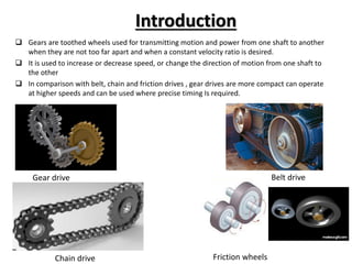
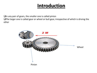
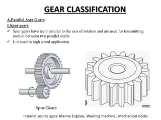
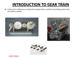
This document discusses gears and gear trains. It begins by defining gears as toothed wheels used to transmit motion and power between two shafts. Gears can increase or decrease speed and change the direction of motion.
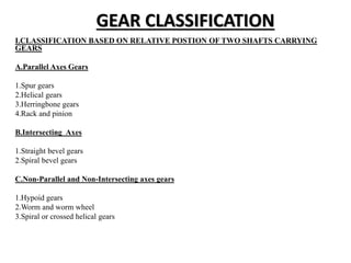
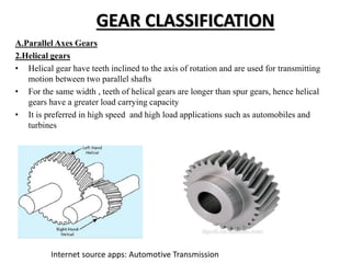
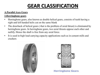
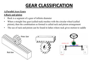
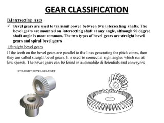
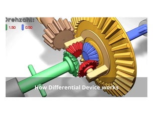
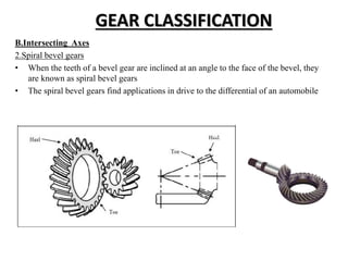
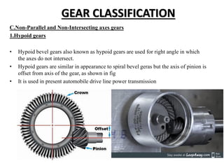
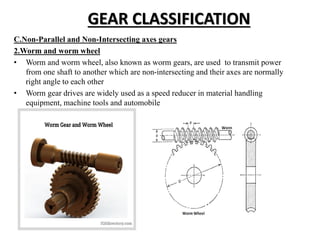
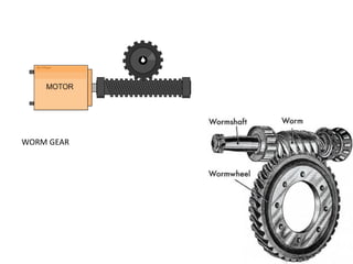
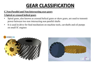
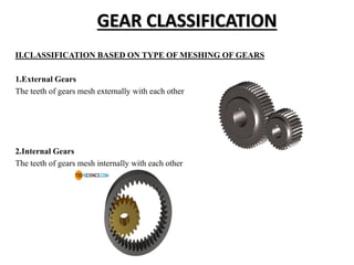
The document then classifies gears based on the relative position of their shafts, including parallel axis gears like spur gears, helical gears, and herringbone gears. It also discusses intersecting axis gears like bevel gears, and non-parallel, non-intersecting axis gears like hypoid gears and worm gears.
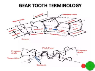
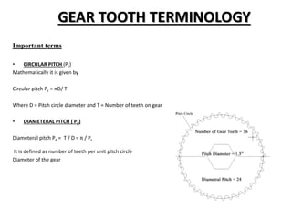
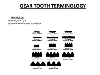
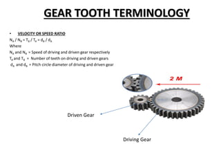
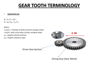
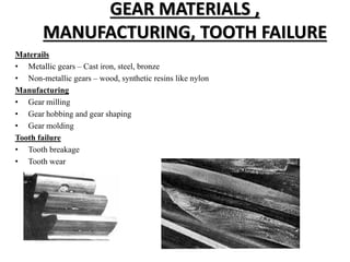
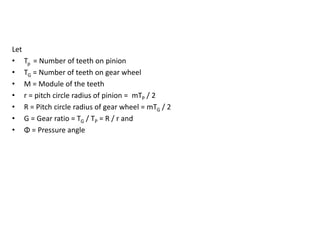
Key gear terminology is introduced, such as circular pitch, diametral pitch, module, velocity ratio, and gear ratio. The document discusses gear materials, manufacturing, tooth
![[PPT] on Steam Turbine](https://cdn.slidesharecdn.com/ss_thumbnails/spsharmafinalppt-140608082156-phpapp01-thumbnail.jpg?width=640&height=640&fit=bounds)