Download to read offline
![IOSR Journal of Electronics and Communication Engineering (IOSR-JECE)
e-ISSN: 2278-2834,p- ISSN: 2278-8735.Volume 6, Issue 3 (May. - Jun. 2013), PP 34-39
www.iosrjournals.org
www.iosrjournals.org 34 | Page
“Designed and Simulation Modified H Shaped” Microstrip Patch
Antenna
Ashwani Patel Singh1
, Satyendra Kr Roy2
, Er Sanjay Gurjar3
1
(ECE Department, Bhagwant University, Ajmer Rajasthan, India)
2
(ECE Department, Bhagwant University, Ajmer Rajasthan, India)
3
(Asst Prof, Ece Department, Bhagwant University Ajmer, Rajasthan, India)
Abstract : This paper describes a new microstrip patch antenna which is presented by using a IE3D software
.These antenna is named as “Designed and simulation of modified H shaped microstrip patch antenna”. A
simulation result has been obtained which states that the microstrip patch antenna possess predictable multi
band characteristics. The result shows that the designed antenna can operated in three different frequency
bands with bandwidth of 2.68%, 10.23%, 5.60%.the resonating behavior makes this antenna suitable for
different type of applications.
Keywords: Patch Antenna, Microstrip antenna, Multiband, narrowband, Radome.
I. INTRODUCTION
With the advance of wireless communication systems and increasing importance of wireless applications in
recent years. Microstrip patch antenna(MPA) has attracted wide interest due to its important characteristics,
such as light weight, low profile and low cost, mechanically robust, simple to manufacture, easy to integrated
with RF devices, allow multi-frequency operation to be achieved ,etc. However, its further use in specific
systems is limited because of its relatively narrow bandwidth. It derives its name from the fact that it is formed
by suspending a single metal patch over another larger metallic plate with a dielectric sheet in between the two
pieces. [1]-[2]Some patch antennas use dielectric spacers between the two plates instead of a continuous sheet in
order to achieve better bandwidth. The increased production and use of portable electronic equipment has
increased the need for a reliable and compact antenna. Patch-type microstrip antennas have met this need, and
are now built-in to cellular phones, palm electronic devices, ,as well as laptop computers and wireless local area
network (LAN) equipment. A patch antenna assembly is commonly enclosed in a protective white or black
plastic case, called a radome [3]-[4] in order to shield the antenna from inclement weather and make it easier to
mount. Patch antennas are thin, lightweight, and relatively simple to construct, modify or customize. These
antennas are commonly fabricated into rectangular, square, elliptical, or circular shapes[5].
Patch type microstrip antennas have met this need, and are now built in to cellular phones, palm electronic
devices as well as laptop computers and wireless local area network (LAN) equipment A patch antenna can be
designed to receive and transmit over a wide range of frequencies using the self similarity properties associated
with the structures.
II. DESCRIPTION OF PROPOSED ANTENNA
The antenna is designed by IE3D structure simulator engine by zeland software and is fed by single
coaxial probe feed .After feeding the antenna structure are further simulated over IE3D simulation software.
These simulations are continuous till an optimum result is obtained.
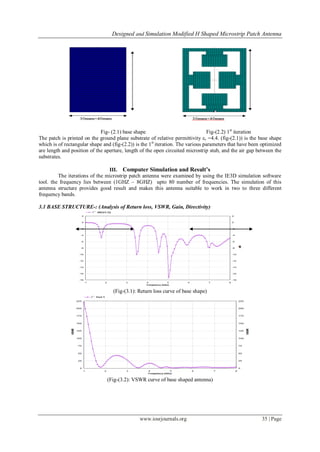
2.1 DESIGN OF MODIFIED SHAPED
The geometry of an antenna is substitute on a finite rectangular ground plane of dimensions (30mm ×
40mm) ,the patch element has been printed on the top of substrate (ztop = 1.6, εr = 4.4, loss of tangent =0.02) ,
the feed point has been given on the lower of the rectangular surface .](https://image.slidesharecdn.com/g0633439-150120233303-conversion-gate02/85/Designed-and-Simulation-Modified-H-Shaped-Microstrip-Patch-Antenna-1-320.jpg)
![IOSR Journal of Electronics and Communication Engineering (IOSR-JECE)
e-ISSN: 2278-2834,p- ISSN: 2278-8735.Volume 6, Issue 3 (May. - Jun. 2013), PP 34-39
www.iosrjournals.org
www.iosrjournals.org 34 | Page
“Designed and Simulation Modified H Shaped” Microstrip Patch
Antenna
Ashwani Patel Singh1
, Satyendra Kr Roy2
, Er Sanjay Gurjar3
1
(ECE Department, Bhagwant University, Ajmer Rajasthan, India)
2
(ECE Department, Bhagwant University, Ajmer Rajasthan, India)
3
(Asst Prof, Ece Department, Bhagwant University Ajmer, Rajasthan, India)
Abstract : This paper describes a new microstrip patch antenna which is presented by using a IE3D software
.These antenna is named as “Designed and simulation of modified H shaped microstrip patch antenna”. A
simulation result has been obtained which states that the microstrip patch antenna possess predictable multi
band characteristics. The result shows that the designed antenna can operated in three different frequency
bands with bandwidth of 2.68%, 10.23%, 5.60%.the resonating behavior makes this antenna suitable for
different type of applications.
Keywords: Patch Antenna, Microstrip antenna, Multiband, narrowband, Radome.
I. INTRODUCTION
With the advance of wireless communication systems and increasing importance of wireless applications in
recent years. Microstrip patch antenna(MPA) has attracted wide interest due to its important characteristics,
such as light weight, low profile and low cost, mechanically robust, simple to manufacture, easy to integrated
with RF devices, allow multi-frequency operation to be achieved ,etc. However, its further use in specific
systems is limited because of its relatively narrow bandwidth. It derives its name from the fact that it is formed
by suspending a single metal patch over another larger metallic plate with a dielectric sheet in between the two
pieces. [1]-[2]Some patch antennas use dielectric spacers between the two plates instead of a continuous sheet in
order to achieve better bandwidth. The increased production and use of portable electronic equipment has
increased the need for a reliable and compact antenna. Patch-type microstrip antennas have met this need, and
are now built-in to cellular phones, palm electronic devices, ,as well as laptop computers and wireless local area
network (LAN) equipment. A patch antenna assembly is commonly enclosed in a protective white or black
plastic case, called a radome [3]-[4] in order to shield the antenna from inclement weather and make it easier to
mount. Patch antennas are thin, lightweight, and relatively simple to construct, modify or customize. These
antennas are commonly fabricated into rectangular, square, elliptical, or circular shapes[5].
Patch type microstrip antennas have met this need, and are now built in to cellular phones, palm electronic
devices as well as laptop computers and wireless local area network (LAN) equipment A patch antenna can be
designed to receive and transmit over a wide range of frequencies using the self similarity properties associated
with the structures.
II. DESCRIPTION OF PROPOSED ANTENNA
The antenna is designed by IE3D structure simulator engine by zeland software and is fed by single
coaxial probe feed .After feeding the antenna structure are further simulated over IE3D simulation software.
These simulations are continuous till an optimum result is obtained.
2.1 DESIGN OF MODIFIED SHAPED
The geometry of an antenna is substitute on a finite rectangular ground plane of dimensions (30mm ×
40mm) ,the patch element has been printed on the top of substrate (ztop = 1.6, εr = 4.4, loss of tangent =0.02) ,
the feed point has been given on the lower of the rectangular surface .](https://image.slidesharecdn.com/g0633439-150120233303-conversion-gate02/75/Designed-and-Simulation-Modified-H-Shaped-Microstrip-Patch-Antenna-1-2048.jpg)
![Designed and Simulation Modified H Shaped Microstrip Patch Antenna
www.iosrjournals.org 39 | Page
S.NO SHAPE FREQUENCIES RETURN
LOSS
BANDWIDTH GAIN
1. BASE
SHAPE
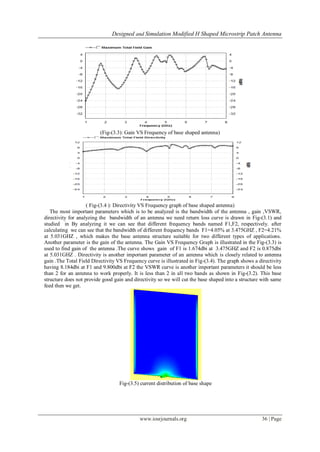
F1 -10.08 4.05% 1.674
2. F2 -17.27 4.21% 0.857
1. FINAL
PATCH
SHAPE
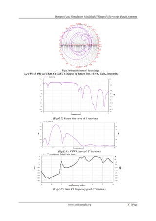
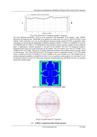
F1 -13.39 2.68% 3.587
2. F2 -23.37 10.23% 3.09
3. F3 -20.23 5.60% 0.718
IV. CONCLUSION
“Design and simulation of modified H shaped microstrip patch antenna” with Multi-Band
characteristics has been successfully demonstrated .This antenna works in three different frequency bands as
shown in the return loss curve. The antenna structure also provides a good amount of gain and directivity .the
antenna efficiency and radiation efficiency which is quite good enough. Its frequency lies between (2- 8)
GHz and it can be used for various military and wireless applications.
Analyzing this type of structures we can further provide increment in the gain and bandwidth of the
antenna. by changing the substrate and feeding.
Acknowledgement
The author would like to express sincere thanks to my colleague SATYENDRA KR ROY and Guide
ER.SANJAY GURJAR (Asst Prof) of Electronic and Communication Engineering Department of Institute of
Engineering and Technology (IET) Bhagwant University, Ajmer Rajasthan for providing the help to carry out
these work.
References:-
JOURNAL PAPERS
[1] J.J. Huang, F.Q. Shan and J.Z. She Tsinghai University, China “Progress in Electromagnetic Research Symposium 2006,
Cambridge, USA, March 26-29” vol2 no1 page 57to59.
[2] Howel “Microstrip Antennas,”IEEE International Symposium on Antennas and Propagation, Williamsburg Virginia, 1972 pp. 177-
180.
[3] Sachendra N. Sinha, Senior Member, IEEE, and Manish Jain “IEEE antennas and wireless propagation Letters” vol 6.2007
[4] ”A Novel approach of miniaturization of slot Antenna “, Azadegan R, Sarabandi,K, IEEE transactions as,antenna and propagation
vol 5; issue 3 march 2003
[5] Fan Yang and Rahmat Samii, Y, “Applications of electromagnetic band gap (EBG) structures in microwave antenna designs”
microwave millimeters’ wave technology p.p. 528-531, Aug 2002.](https://image.slidesharecdn.com/g0633439-150120233303-conversion-gate02/85/Designed-and-Simulation-Modified-H-Shaped-Microstrip-Patch-Antenna-6-320.jpg)

The document presents the design and simulation of a modified H-shaped microstrip patch antenna, developed using IE3D software. This antenna demonstrates multi-band characteristics, operating in three frequency bands with respective bandwidths of 2.68%, 10.23%, and 5.60%, making it suitable for various applications in wireless communication. The simulation results indicate improved gain and directivity compared to the base design, achieving successful performance metrics across the tested frequency range.