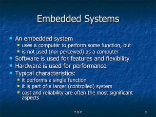
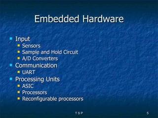
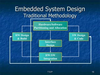
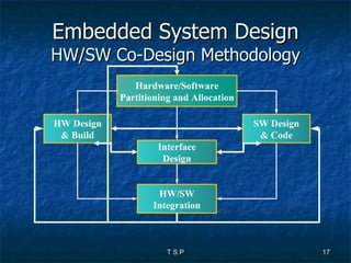
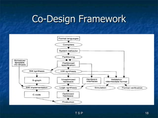
Hardware/Software Co-Design  T S PRADEEPKUMAR SCS, VIT
Outline Embedded Hardware  Embedded Software Issues in Embedded System Design Hardware/ Software Partioning Designing Embedded Systems Co-Design
Embedded Systems An embedded system  uses a computer to perform some function, but is not used (nor perceived) as a computer Software is used for features and flexibility Hardware is used for performance Typical characteristics: it performs a single function it is part of a larger (controlled) system cost and reliability are often the most significant aspects
Embedded Systems SOC IP Based Design System Environment PCB  Design Satellite Macro-Cell Micro-Cell Zone 2: Urban Zone 1: In-Building Pico-Cell Zone 4: Global Zone 3: Suburban Firmware CORE Software SOC   µ P/C Analog Embedded Software Memory Embedded  System Design
Embedded Hardware Input Sensors Sample and Hold Circuit A/D Converters Communication UART Processing Units ASIC Processors Reconfigurable processors
Embedded Hardware Memories RAM, ROM, Flash, Cache Output D/A Converters, Actuators
Embedded Software Real Time Operating Systems General Requirements Scheduling in RTOS Aperiodic Periodic Real Time Databases Other Software Architectures Function Queue Scheduling Round Robin (with Interrupts)
Issues while Designing ES Choosing Right platform Memory and I/O Requirements WDT, Cache, Flash memory, etc Processors Choice PLC Micro Controller or DSP ASIC or FPGA
Issues… Hardware Software Tradeoff Porting Issues of OS in the Target Board
Hardware /Software Partitioning Definition A HW/SW partitioning algorithm implements a  specification  on some sort of  multiprocessor architecture Usually Multiprocessor architecture = one CPU + some ASICs on CPU bus
Hardware /Software Partitioning Terminology Allocation Synthesis methods which design the multiprocessor topology along with the Process Elements and SW architecture Scheduling The process of assigning Process Element (CPU and/or ASICs) time to processes to get executed
Hardware /Software Partitioning Hw/Sw partitioning can speedup software Can reduce energy too In most partitioning algorithms Type of CPU is fixed and given ASICs must be synthesized
Designing of Embedded Systems There are five stages of development of Embedded Systems Requirement Analysis Design Data Structures, Software Architecture, Interfaces and algorithms Coding Testing Maintenance
Designing of Embedded Systems There are three Design Flows Waterfall Model Spiral Model Successive refinement For Designing, Unified Modeling Language (UML) is used
Embedded System Design Traditional Methodology HW Design & Build Hardware/Software Partitioning and Allocation SW Design & Code Interface Design HW/SW Integration
Problems with Past Design Method Lack of unified system-level representation Can't verify the entire HW-SW system Hard to find incompatibilities across HW-SW boundary (often found only when prototype is built)  Architecture is defined  a priori , based on expert evaluation of the functionality and constraints Lack of well-defined design flow Time-to-market problems Specification revision becomes difficult
Embedded System Design HW/SW Co-Design Methodology HW Design & Build Hardware/Software Partitioning and Allocation SW Design & Code Interface Design HW/SW Integration
Co-Design Framework
Co-Design The software functionality should be partitioned in such a fashion that processors in the system do not get overloaded when the system is operating at peak capacity.  This involves simulating the system with the proposed software and hardware architecture.
Co-Design The system should be designed for future growth by considering a scalable architecture, i.e. system capacity can be increased by adding new hardware modules. The system will not scale very well if some hardware or software module becomes a bottleneck in increasing system capacity.
Co-Design Software modules that interact very closely with each other should be placed on the same processor, this will reduce delays in the system. Higher system performance can be achieved by this approach by inter-processor message communication.
Embedded Controller Example: Engine Control Unit (ECU) Task: control the torque produced by the engine by timing fuel injection and spark Major constraints: Low fuel consumption Low exhaust emission
ECU  Task: control injection time (3 sub-tasks) compute air flow compute injection time drive actuators air flow injection time air temperature engine temperature engine speed throttle position look-up table PWM signals air pressure
ECU- Option 1 32 bit CPU A/D Actuations (PWM) Analog inputs Digital inputs compute air flow compute injection time drive actuators air flow injection time air temperature engine temperature engine speed throttle position look-up table PWM signals air pressure
ECU- Option 2 16 bit CPU A/D Actuations (PWM) Analog inputs Digital inputs FPGA compute air flow compute injection time drive actuators air flow injection time air temperature engine temperature engine speed throttle position look-up table PWM signals air pressure
ECU- Option 3 8 bit CPU DSP Actuations (PWM) Analog  inputs Digital inputs FPGA A/D compute air flow compute injection time drive actuators air flow injection time air temperature engine temperature engine speed throttle position look-up table PWM signals air pressure
Thank You

Design of embedded systems tsp

  • 1.
    Hardware/Software Co-Design T S PRADEEPKUMAR SCS, VIT
  • 2.
    Outline Embedded Hardware Embedded Software Issues in Embedded System Design Hardware/ Software Partioning Designing Embedded Systems Co-Design
  • 3.
    Embedded Systems Anembedded system uses a computer to perform some function, but is not used (nor perceived) as a computer Software is used for features and flexibility Hardware is used for performance Typical characteristics: it performs a single function it is part of a larger (controlled) system cost and reliability are often the most significant aspects
  • 4.
    Embedded Systems SOCIP Based Design System Environment PCB Design Satellite Macro-Cell Micro-Cell Zone 2: Urban Zone 1: In-Building Pico-Cell Zone 4: Global Zone 3: Suburban Firmware CORE Software SOC µ P/C Analog Embedded Software Memory Embedded System Design
  • 5.
    Embedded Hardware InputSensors Sample and Hold Circuit A/D Converters Communication UART Processing Units ASIC Processors Reconfigurable processors
  • 6.
    Embedded Hardware MemoriesRAM, ROM, Flash, Cache Output D/A Converters, Actuators
  • 7.
    Embedded Software RealTime Operating Systems General Requirements Scheduling in RTOS Aperiodic Periodic Real Time Databases Other Software Architectures Function Queue Scheduling Round Robin (with Interrupts)
  • 8.
    Issues while DesigningES Choosing Right platform Memory and I/O Requirements WDT, Cache, Flash memory, etc Processors Choice PLC Micro Controller or DSP ASIC or FPGA
  • 9.
    Issues… Hardware SoftwareTradeoff Porting Issues of OS in the Target Board
  • 10.
    Hardware /Software PartitioningDefinition A HW/SW partitioning algorithm implements a specification on some sort of multiprocessor architecture Usually Multiprocessor architecture = one CPU + some ASICs on CPU bus
  • 11.
    Hardware /Software PartitioningTerminology Allocation Synthesis methods which design the multiprocessor topology along with the Process Elements and SW architecture Scheduling The process of assigning Process Element (CPU and/or ASICs) time to processes to get executed
  • 12.
    Hardware /Software PartitioningHw/Sw partitioning can speedup software Can reduce energy too In most partitioning algorithms Type of CPU is fixed and given ASICs must be synthesized
  • 13.
    Designing of EmbeddedSystems There are five stages of development of Embedded Systems Requirement Analysis Design Data Structures, Software Architecture, Interfaces and algorithms Coding Testing Maintenance
  • 14.
    Designing of EmbeddedSystems There are three Design Flows Waterfall Model Spiral Model Successive refinement For Designing, Unified Modeling Language (UML) is used
  • 15.
    Embedded System DesignTraditional Methodology HW Design & Build Hardware/Software Partitioning and Allocation SW Design & Code Interface Design HW/SW Integration
  • 16.
    Problems with PastDesign Method Lack of unified system-level representation Can't verify the entire HW-SW system Hard to find incompatibilities across HW-SW boundary (often found only when prototype is built) Architecture is defined a priori , based on expert evaluation of the functionality and constraints Lack of well-defined design flow Time-to-market problems Specification revision becomes difficult
  • 17.
    Embedded System DesignHW/SW Co-Design Methodology HW Design & Build Hardware/Software Partitioning and Allocation SW Design & Code Interface Design HW/SW Integration
  • 18.
  • 19.
    Co-Design The softwarefunctionality should be partitioned in such a fashion that processors in the system do not get overloaded when the system is operating at peak capacity. This involves simulating the system with the proposed software and hardware architecture.
  • 20.
    Co-Design The systemshould be designed for future growth by considering a scalable architecture, i.e. system capacity can be increased by adding new hardware modules. The system will not scale very well if some hardware or software module becomes a bottleneck in increasing system capacity.
  • 21.
    Co-Design Software modulesthat interact very closely with each other should be placed on the same processor, this will reduce delays in the system. Higher system performance can be achieved by this approach by inter-processor message communication.
  • 22.
    Embedded Controller Example:Engine Control Unit (ECU) Task: control the torque produced by the engine by timing fuel injection and spark Major constraints: Low fuel consumption Low exhaust emission
  • 23.
    ECU Task:control injection time (3 sub-tasks) compute air flow compute injection time drive actuators air flow injection time air temperature engine temperature engine speed throttle position look-up table PWM signals air pressure
  • 24.
    ECU- Option 132 bit CPU A/D Actuations (PWM) Analog inputs Digital inputs compute air flow compute injection time drive actuators air flow injection time air temperature engine temperature engine speed throttle position look-up table PWM signals air pressure
  • 25.
    ECU- Option 216 bit CPU A/D Actuations (PWM) Analog inputs Digital inputs FPGA compute air flow compute injection time drive actuators air flow injection time air temperature engine temperature engine speed throttle position look-up table PWM signals air pressure
  • 26.
    ECU- Option 38 bit CPU DSP Actuations (PWM) Analog inputs Digital inputs FPGA A/D compute air flow compute injection time drive actuators air flow injection time air temperature engine temperature engine speed throttle position look-up table PWM signals air pressure
  • 27.