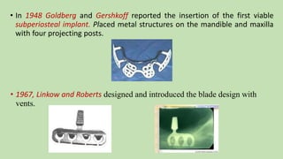
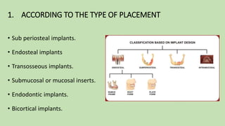
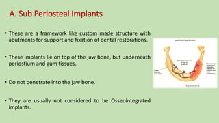
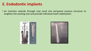
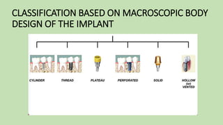
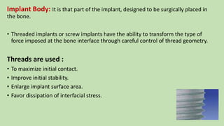
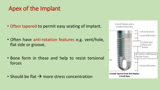
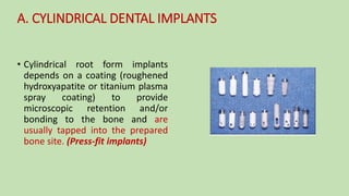
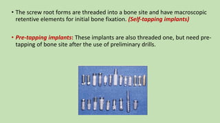
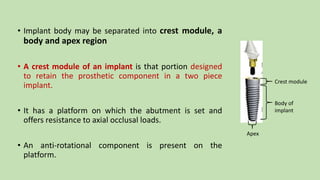
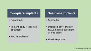
Dental Implant Designs
Guided by:
Dr. U.M. Radke Dr. N.A. Pande Dr. S Deshmukh
HOD & Guide Professor Reader
Dr. T.K. Mowade Dr. R. Banerjee DR. A. Chandak
Reader Reader READER
Presented by:-
Dr. Richa Sahai
II MDS
Introduction
• In a review article by Esposito et al , bone quality and volume were cited as
major determinants for both early and late implant failures.
• Friberg et al reported an implant failure rate of 32% for those implants which
showed inadequate initial stability.
• Although bone density and quantity are local factors and cannot be controlled,
implant design and surgical technique may be adapted to the specific bone
situation to improve the initial implant stability.
• While different implant designs have shown similar initial stabilities
in dense bone, implant stability in soft low density bone may be
influenced by implant design.
• Major contributors to initial implant stability have been suggested to
be implant length, diameter, surface texture and thread
configuration.
History
3000 yrs ago:
• Egyptian mummies  gold wire implants
• Egyptians used - seashells , semi-precious stones, Ivory and bones .
• Iron dental implant  Roman soldier discovered in Europe
• In 1809 Maggiolo  gold roots placed into fresh extraction sites
• Greenfield (1909) placed the first really successful dental implant
• In 1948 Goldberg and Gershkoff reported the insertion of the first viable
subperiosteal implant. Placed metal structures on the mandible and maxilla
with four projecting posts.
• 1967, Linkow and Roberts designed and introduced the blade design with
vents.
• In 1970 Roberts introduced ramus frame implant.
• 1975, Sollier and Small introduced transosteal mandibular staple bone plate
placed through a submental incision and attached to mandible with multiple
fixation and two transosteal screws to support a full arch prosthesis.
• In 1952, in the university of Sweden, Professor of orthopedics Per-Ingvar
Branemark had a lucky accident – what most scientists call serendipity
(occurrence of events by chance in a fortunate way)..
• He subsequently observed that – under carefully controlled conditions – titanium
could be structurally integrated into living bone with a very high degree of
predictability and without long-term soft tissue inflammation or ultimate fixture
rejection.
• Later, he named this phenomenon Osseointegration.
Classifications of implant designs
1. ACCORDING TO THE TYPE OF PLACEMENT
• Sub periosteal implants.
• Endosteal implants
• Transosseous implants.
• Submucosal or mucosal inserts.
• Endodontic implants.
• Bicortical implants.
A. Sub Periosteal Implants
• These are a framework like custom made structure with
abutments for support and fixation of dental restorations.
• These implants lie on top of the jaw bone, but underneath
periostium and gum tissues.
• Do not penetrate into the jaw bone.
• They are usually not considered to be Osseointegrated
implants.
Indications
In severely resorbed,
toothless lower jaw
bone,
Contraindications
Progressive bone
resorption
Poor quality cortical
layer (eg.unhealed
extraction sockets) at
site of implantation
Recent (within 12
months) irradiation
of the head
B. Endosteal implants
• A device which is placed into the alveolar bone and/or basal bone of the
mandible or maxilla.
• Transect only one cortical plate.
• Designed for toothless lower jaw only.
1. Blade Implants
• It consist of thin plates in the form of blade embedded into
the bone.
2. Ramus Frame Implants
• Horse shoe shaped stainless steel device Inserted into the
mandible from one retromolar pad to the other.
• It passes through the anterior symphysis area.
3. Root Form Implants
• Designed to mimic the shape of the tooth for directional
load distribution
C. Trans-osseous implants (staple bone implant , mandibular staple implant,
trans-mandibular implant)
• Combines the subperiosteal and endosteal components.
• Penetrates both cortical plates.
• These implants are not in much use any more, because they
necessitate an extraoral surgical approach to their
placement.
• Required bone should be more than 6mm in vertical height
and more than 5mm in labial to lingual width.
D. Submucosal or mucosal inserts
• Mushroom shaped, non-implanted, retention devices use to stabilize full or
partial maxillary and mandibular removable prostheses.
• Purpose of creating retention devices, that would reduce need for relining the
denture.
• Requires more than 2 to 3mm mucosal tissue.
E. Endodontic implants
• An insertion extends through root canal into periapical osseous structure to
lengthen the existing root and provide individual tooth stabilization.
CLASSIFICATION BASED ON MACROSCOPIC BODY
DESIGN OF THE IMPLANT
Force direction and influence on implant body design
• bone is weaker when loaded under an angled force
• greater the angle of load, the greater the stresses
• implant body long axis should be perpendicular to the curve of wilson and curve
of spee.
• axial alignment places less shear stress on the overall implant system and
decrease the risk of complications as screw loosening and fatigue fractures
So:
Virtually all implant are designed for placement perpendicular to occlusal plan18
Implant Body: It is that part of the implant, designed to be surgically placed in
the bone.
• Threaded implants or screw implants have the ability to transform the type of
force imposed at the bone interface through careful control of thread geometry.
Threads are used :
• To maximize initial contact.
• Improve initial stability.
• Enlarge implant surface area.
• Favor dissipation of interfacial stress.
Three geometric thread parameters:
• Thread pitch
• Thread shape
• Thread depth
Thread pitch:
• Distance between two adjacent thread crest.
• No. of threads/implant :- length of implant/ pitch
• More threads  more surface area
Thread Shapes
• The original Branemark screw (introduced in 1965) had
a V-shaped threaded pattern.
• Knefel investigated 5 different thread profiles and
found most favorable stress distribution to be
demonstrated by an ‘asymmetric thread’, profile of
which varied along the length of an implant.
• Recently it has been proposed that a square
crest of the thread with a flank angle of 3
degrees decreases the shear force and
increases the compressive load (Bio-
Horizons Maestro Implant Systems Inc.,
Birmingham, Alabama)
• The shear forces on a V-thread is
approximately 10 times, greater than shear
force on a square thread.
Thread Depth
Implant Diameter
• The dimension measured from the peak of widest
thread to the same point on opposite side of implant.
• Wider implants have advantage of increased surface
area thereby increase amount of total bone contact.
• Increasing the diameter in 3mm implant by 1mm
increases the surface area by 35% over same length
in overall surface.
Implant body size and design relation to fracture
26
Therefore, an implant or component 2 times as wide is
16 times more resistant to fracture.
Considering the same equations, it can be shown that an abutment screw,
which has a smaller cross-sectional area than an implant (typically about 2 mm},
is more susceptible to fracture.
This is particularly true when the abutment screw comes loose and bears a
large, disproportionate component of a transverse load to the occlusal surface.
27
Annulus portion of implant:
• Space within the implant body below the
abutment screw.
• Wall thickness of implant body in region
below abutment screw controls the
resistance to fatigue fracture.
• When bone loss occurs to annulus,
implant body fracture is imminent
abutment screw length is an important
implant design issue and should be as
long as possible
Implant Length
• It is the dimension from the platform to the apex of implant.
• It has been said that longer implant guarantee better success
rates and prognosis.
• Failure in 7mm or less length implants are more.
Apex of the Implant
• Often tapered to permit easy seating of implant.
• Often have anti-rotation features e.g. vent/hole,
flat side or groove.
• Bone form in these and help to resist torsional
forces
• Should be flat  more stress concentration
• Cylindrical root form implants
depends on a coating (roughened
hydroxyapatite or titanium plasma
spray coating) to provide
microscopic retention and/or
bonding to the bone and are
usually tapped into the prepared
bone site. (Press-fit implants)
A. CYLINDRICAL DENTAL IMPLANTS
• The screw root forms are threaded into a bone site and have macroscopic
retentive elements for initial bone fixation. (Self-tapping implants)
• Pre-tapping implants: These implants are also threaded one, but need pre-
tapping of bone site after the use of preliminary drills.
• Implant body may be separated into crest module, a
body and apex region
• A crest module of an implant is that portion designed
to retain the prosthetic component in a two piece
implant.
• It has a platform on which the abutment is set and
offers resistance to axial occlusal loads.
• An anti-rotational component is present on the
platform.
Crest module
Body of
implant
Apex
• The crest module of an implant should be slightly larger than the outer thread
diameter:
• Prevent ingress of bacteria or fibrous tissue
• Increases surface area which contributes to decrease in stress at the crestal
region.
• The collar: where implant emerges from the bone and passes through the
overlying soft tissue.
• A polished collar of minimum height should be designed on the superior
portion of the crest just below the prosthetic platform
• A 0.5 mm collar length provides a desirable smooth surface close to peri-gingival
area.
Two-piece implants
• Branemark
• implant body + separate
abutment
• Two interphases
One-piece implants
• Schroeder
• implant body + the soft
tissue healing abutment
as one piece
• One interphase
DCNA 2006;50(3):33
B. THREADED DENTAL IMPLANTS
• The surface of the implant is threaded, to increase the surface area of the
implant.
• This results in distribution of forces over a greater peri-implant bone volume.
C. PLATEAU- DENTAL IMPLANTS
• Plateau shaped implant with sloping shoulder.
D. SOLID DENTAL IMPLANTS
• They are of circular cross section without vent or
hollow in the body.
E. PERFORATED DENTAL IMPLANTS
• The implants of inert micro porous membrane material (mixture of
cellulose acetate ) in intimate contact with and supported by the layer
of perforated metallic sheet material (pure titanium)
F. HOLLOW DENTAL IMPLANTS
• Hollow design in the apical portion systematically arranged
perforations on the sides of the implant.
• Increased anchoring surface
G. VENTED DENTAL IMPLANTS
• It is hydroxy-apetite coated cylinder implant.
• Patented vertical groove connecting to the apical vents were
designed to facilitate seating and allow bone ingrowth to
prevent rotation.
Core-vent, micro-vent and screw- vent implants
• Developed by Dr. Gerald Niznick
• The Core-Vent and Micro-Vent implants
are made of a titanium alloy (90%
titanium, 6% aluminium, 4% vanadium).
• The Screw-Vent is made of commercially
pure titanium.
Micro-vent Core-ventScrew-vent
Advantages of vent
• Bone can grow through vent and
resist torsional load applied to
implant .
• May also increase surface area
available to transmit compressive
load to bone
Disadvantages of vent
• When implant placed through sinus
floor or exposed through cortical
plate may lead to mucus
entrapment.
• If vent is several mm in height
region ,may fill with fibrous tissue,
decrease bony contact.
• The Core-Vent implant depending on length of implant, it has apical
one-half to one third hollow basket design with four to eight vents.
• The coronal half has some threads on outer surface and a non-
threaded area at coronal end. The coronal opening is either a
hexagonal shaped hole or threaded internally.
The Micro-Vent implant is a cylindrical implant with a horizontal vent
at apical end.
• The apical end also has some threads and remainder of threads are
circumferential smooth grooves instead of continual threads.
The Screw-Vent implant is a threaded cylindrical implant.
• The apical end has horizontal and vertical vent, threaded to
end for a self-tapping option.
• The coronal ends in a cylindrical collar, if bone resorption
occurs in this area , resorption exposes a smooth surface at
the crest instead of threads.
• The Screw-Vent is available in 3.75 mm diameter with
either threaded or hexagonal hole, in 7.0, 10.0, 13.0 and
16.0 mm length.
Mini Implants
1. Mini subperiosteal implants
• Developed by Dr. Gustav Dahl and Ronald Cullen.
• Narrow diameter implant around 2mm diameter.
• Initially they were designed as temporary implants to hold
restorations while permanent implant were healing.
Indications:
• anterior mandible
• in stabilizing overdentures
• in area of tooth replacement that are too narrow for
conventional implants.
2. Crete mince implants (Michel Chercheve)
• These implants are also known as C-M or M-C implants.
• Available in varying lengths.
• They are used in the cases where the ridge thickness is as less as
2.5mm.
• These lack strength due to their thinness.
• They add retention to long term fixed bridge prosthesis.
3. Mini Transitional Implants (MTIs)
• These implants are smaller implants than Crete mince implants
• Used as interim devices, placed to retain temporary prostheses, while
permanent implant are healing.
CLASSIFICATION BASED ON THE SURFACE OF
THE IMPLANT
A. SMOOTH SURFACE IMPLANT
• Wennerberg and coworkers have suggested that
smooth is used to describe abutments, whereas
the terms minimally rough (0.5 to 1 µm),
intermediately rough (1 to 2 µm), and rough (2
to 3 µm) be used (apart from porous surfaces)
for implanted surfaces.
• To prevent microbial plaque retention.
B. MACHINED SURFACE IMPLANTS
• For the purpose of better anchorage of implant to the
bone, the surface of the implant is machined.
C. TEXTURED SURFACE IMPLANTS
• The implants of increasing surface roughness of the
area to which bone can bond.
D. COATED SURFACE IMPLANT
Braz. Dent. J. vol.16 no.1, Jan./Apr. 2005
• Hydroxy-apatite
• Ceramic
• Peptide
• Bone-morphogenic protein coating
Plasma spray-Coating:
1. Titanium plasma sprayed (Hahn & Palich)
• Porous or rough titanium surfaces have been fabricated by plasma spraying a
powder form of molten droplets at high temperatures.
• The plasma sprayed layer thickness - 0.04mm – 0.05mm.
• Studies concluded that rough and porous surface showed a three dimensional
interconnected configuration likely to achieve bone-implant attachment for stable
anchorage. (Schroeder et al).
2. Hydroxyapatite coating (De Groot)
• Block & Thomas showed an accelerated bone formation and
maturation around HA-coated implants in dogs when compared with
non-coated implants.
• Cook et al measured the thickness of HA – coating after 32 weeks , and
showed a consistent thickness of 50 µm.
• Implants of solid sintered Hydroxyapatite have been susceptible to
fatigue failure. This can be altered by use of calcium phosphate coating
(CPC) on majority of implants done by plasma spray technique.
Additional advantages of HA over Titanium plasma sprayed
Faster healing bone
interface
Stronger interface than
TPS
Less corrosion.
The clinical advantages of Titanium plasma sprayed or HA coating
Increased surface area
Increased roughness for
initial stability
Strong bone to implant
interface
Disadvantages of HA Coating:
• Flaking, cracking, or scaling upon insertion.
• Increased plaque retention when above bone.
• Increased cost.
3.Blasting with particles of various diameters
• In this approach, the implant surface is bombarded with particles of
aluminum oxide (Al2O3) or titanium oxide (TiO2), and by abrasion, a
rough surface.
4. Chemical etching
• The metallic implant is immersed into an acidic
solution (hydrochloric-sulfuric acid), which erodes its
surface, creating pits of specific dimensions and
shape.
• Concentration of acidic solution, time, and
temperature are factors determining the result of
chemical attack and microstructure of surface.
Newer concept
Grit blasted/Acid Etched depth structuring:
• Depth structuring includes four phases:
 Sandblasting,
 Etching,
 Neutralization and
 Cleaning
• This surface is produced by a large grit (250 to 500 µm) blasting process,
followed by etching with hydrochloric-sulfuric acid.
• Busser et al. showed that implants with sandblasted and acid etched
surfaces had higher bone to implant contact percentages than
implants with titanium plasma sprayed surfaces.
• The titanium surface sandblasted and acid etched, forming a rough
surface improved the initial implant stability in bone of low-density
and increased the quality of the bone to implant interface.
Porous
Diffusion-bonded microsphere interface
• It is conducted at 1250˚C in a vacuum for 1 hour.
• Unlike plasma sprayed sintering, in diffusion the spherical powder of metallic or
ceramic material become a coherent mass with the metallic core of the implant
body.
• The final structure contains about 35% volume of uniformly distributed pores of
50-250 µm contiguous with the interface, to a depth of 300 µm.
• Bony in-growth within the interlocking porosities provides 3-D interlock that
offers substantial resistance to torsional and other applied forces.
Endopore System
• This implant system came in late 1990s.
• This implant is coated with hydroxyapatite (HA) , which
increases bone contact.
• Sintering titanium alloy powder to a machined titanium
surface using high temperature and controlled atmospheric
pressure produces a uniform porous surface.
• It is a unique, truncated cone-shaped design that uses a
multilayered porous surface geometry over most of its
length to achieve integration by three-dimensional bone
ingrowth
4. According to Material
A. METALLIC IMPLANT
• Most popular material in use today is TITANIUM.
• Other metallic implants are:
• stainless steel
• cobalt chromium molybdenum alloy
• Vitallium
B. CERAMIC & CERAMIC COATED IMPLANTS
• These materials are also used to coat metallic implants.
• These ceramics can either be plasma sprayed or coated to
produce bio active surface.
• Non reactive ceramic materials are also present.
C. POLYMERIC IMPLANT
• In the form of polymethylmethacrylate and polytetrafluoroethylene.
• Have only been used as adjuncts stress distribution along with implants
rather than used as implants by themselves.
D. CARBON IMPLANTS
• Made up of carbon with stainless steel.
• Modulus of elasticity equivalent to bone and dentine.
• Brittleness leads to fracture.
5. According to abutment attached
External systems comprised of the external hex
The design has disadvantages:
• There is little engaging length or slip of restorative component over
the hexagonal portion of implant head, so it is necessary to check
that secondary component is seated fully over the primary hex.
• Great strain is placed on the connecting
screw.
• The screw is essentially the only device
resisting strain in the connection
apparatus, so it tends to loosen and/or
fracture relatively easily
• A high incidence of screw loosening of up
to 40% was found for this type of
abutment connection, as reported by Jemt
et al and by Becker.
• In contrast, Levine et al reported a far lower rate of abutment
loosening (3.6% to 5.3%) with conical implant-abutment connections,
restoring single-tooth replacements.
• Sutter et al proposed an 8-degree taper connection, referred to in the
literature as the ITI Morse Taper, between implant and abutment as an
optimal combination of predictable vertical positioning and self-locking
characteristics.
Morse taper screw posts
• Morse taper screw posts form a much stronger connection than
external systems because the post runs deep within the implant
body.
• The internal walls of the implant usually have a taper of about 8°.
• Beat R. M. et al did a study to compare between the 8-degree Morse
Taper and the butt joint (external hex) as connections between an
implant and an abutment. The comparison indicates the superior
mechanics of conical abutment connections.
Internal connections
• The tongue (that portion which locks into the notches inside the implant
body to achieve the antirotational effect) and screw of the secondary
component pass down inside the implant body.
• Further inside body the tongue posses, more engagement length and less
strain that falls on retaining screw.
These connections are further characterized :
• A slip-fit joint where a slight space exists between the
components.
• A friction-fit joint where no space exists between the
components
• The surfaces can have a butt joint, which consists of 2
right-angle flat surfaces contacting or a bevel joint,
where surfaces are angled either internally or
externally.
• Various autorotation devices have been used, the most common being some
form of hexagon, which can engage into reciprocal slots on the inner surface
of implant.
• Most internal connection systems make available 6 or 8 rotational lock
positions for the restorative components. The greater number of potential
lock positions, more difficult it is to ensure that secondary component is
oriented correctly.
Internal Anti rotational
features:
1. Octagonal A. Cylinder hex
2. Hexagonal B. Cam tube
3. Cone screw C. Cam cylinder
Platform Switching technology
• The concept of “platform switching” refers to the use of a
smaller-diameter abutment on a larger-diameter implant collar.
• This connection shifts the perimeter of the IAJ inward toward the
central axis (i.e. the middle) of the implant.
• Lazzara and Porter theorize that the inward movement of the IAJ
in this manner also shifts the inflammatory cell infiltrate inward
and away from the adjacent crestal bone, which limits the bone
change that occurs around the coronal aspect.
Laser-Lok Technology
• Laser-Lok microchannels is a series of cell-sized circumferential channels that
are precisely created using laser ablation technology.
• These are a series of precision-engineered 8 and 12 micron grooves on the collar
of dental implants.
• This patented laser surface is unique within the industry as the only surface
treatment shown to attach and retain both hard and soft tissue
• According to various vivo studies it was shown that a
microchannel pattern of 8 and 12 microns improved soft
tissue integration, controlled cell ingrowth, increased
bone and tissue attachment and reduced bone loss.
• The mean crestal bone loss for implants with Laser-Lok
microchannels was only 0.59mm versus 1.94mm for the
control implant.
• These implant surface establishes a physical connective
tissue attachment.
Newer Concept
Laser-Lok applied to abutments
• Used to create a biologic seal along with Laser-Lok implants to establish
superior osseointegration.
In a recent study, Laser-Lok abutments and standard abutments were randomly
placed on implants with a grit-blasted surface to evaluate the differences.
• In this , a small band of Laser- Lok microchannels was shown to inhibit
epithelial downgrowth and establish a connective tissue attachment (unlike
Sharpey fibers) similar to Laser-Lok implants.
Int J Periodontics Restorative Dent , Volume 30, 2010. p. 245-255.
Review of Literature
1. A study on the Effects of implant thread geometry on percentage of
osseointegration and resistance to reverse torque in the tibia of
rabbits.
• Conclusion - The square thread design may be more effective for use
in endo-osseous dental implant systems.
Studies evaluating the effect of thread shape
Studies evaluating the effect of thread pitch on load
transfer and bone-to-implant contact
Studies evaluating the effect of thread depth and width
on stress distribution and bone-to-implant contact
Influence of implant length and diameter on stress distribution: A finite
element analysis.
• Conclusion
- Increased implant diameter better dissipated the simulated
masticatory force and decreased the stress around the implant neck.
- The highest reduction in stress compared to the reference implant
(100%, 3.6 mm wide, 12 mm long) was obtained for the diameter of
4.2 mm .
- From a biomechanical perspective, the optimum choice was an
implant with the maximum possible diameter allowed by the
anatomy.
Himmlová, L., Dostálová, T., Kácovský, A., & Konvic̆ková, S. (2004). Influence of implant length and diameter on stress
distribution: A finite element analysis. The Journal of Prosthetic Dentistry, 91(1), 20–25. doi:10.1016/j.prosdent.2003.08.008
The Effect of Implant Length and Diameter on the Primary Stability in
Different Bone Types
Conclusion –
• In D1 bone, the implant length did not make any significant difference in primary
stability;
• In D3 bone, the primary stability of the implant increased when longer implants
were utilized.
• NP implants presented significantly lower ISQ values compared to the two wider
implants.
• In cases of low bone quality, the optimum increase in the implant length and
diameter should be taken into account to achieve higher primary stability.
Barikani H, Rashtak S, Akbari S, Badri S, Daneshparvar N, Rokn A. The effect of implant length and diameter on the primary
stability in different bone types. J Dent (Tehran). 2013;10(5):449-55.
Influence of implant shape, surface morphology, surgical technique and bone
quality on the primary stability of dental implants
Conclusions
1. The low quality and quantity of bone tissue can be partially compensated using
thicker and longer implants.
2. The influence of the surgical technique is equally important than that of implant
design.
3. Insertion and removal torques increase with increasing implant length and
diameter.
4. Implants with an anodized surface have a higher primary stability than acid
etched and machined implants.
Elias, C. N., Rocha, F. A., Nascimento, A. L., & Coelho, P. G. (2012). Influence of implant shape, surface morphology, surgical technique
and bone quality on the primary stability of dental implants. Journal of the Mechanical Behavior of Biomedical Materials, 16, 169–180.
doi:10.1016/j.jmbbm.2012.10.010
• Although bone density and quantity are local factors and cannot be controlled,
the implant design and surgical technique may be adapted to the specific bone
situation to improve initial implant stability.
• While different implant designs have shown similar initial stabilities in dense
bone, implant stability in soft low density bone may be influenced by implant
design.
• It has been suggested that a combination of microscopic surface topography
and macroscopic levels of implant design (e.g., screw thread profiles) may be
essential to create a stable bone-implant interface in a low density bone.
Conclusion
References
1. Contemporary implant dentistry – Carl E. Misch , 2nd edition
2. Contemporary implant dentistry – Carl E. Misch , 3Rd edition
3. Fundamentals of implant dentistry, Weiss and Weiss
4. Endosteal Dental Implants -Ralf V McKinney Jr
5. Endosseous implants- Georg Watzek
6. Cury P.R.,Sendyk W.R.,Sallum A.W. Factors associated with early and late failure of
osseointegrated implant.Braz J Oral Sci.2003;2
7. Davies S.J.,Gray R.J.M.,Young M.P.J.:Good occlusal practice in the provision of implant
borne prostheses.BDJ 2002;192:79-88
8. Esposito M.,Hirsch J.M.,Lekholm U.,Thomsen P. Biological factors contributing to
failures of osseointegrated oral implants.Euro.J.of Oral Sc.1998;106:527-551
9. Michael D.Wise : Failure in the Restored Dentition: Management and Treatment,1st ed. pp.489-
564,1995
10. Palmer R,Palmer P,Howe L Dental implants: Part 10.Complications and maintenance. BDJ 1999 ;
187:653-658
11. Effect of implant size and shape on implant success rates: A Literature review JPD 2005;94:377-81
12. Himmlová, L., Dostálová, T., Kácovský, A., & Konvic̆ková, S. (2004). Influence of implant length and
diameter on stress distribution: A finite element analysis. The Journal of Prosthetic Dentistry,
91(1), 20–25. doi:10.1016/j.prosdent.2003.08.008
13. Barikani H, Rashtak S, Akbari S, Badri S, Daneshparvar N, Rokn A. The effect of implant length and
diameter on the primary stability in different bone types. J Dent (Tehran). 2013;10(5):449-55.
14. Elias, C. N., Rocha, F. A., Nascimento, A. L., & Coelho, P. G. (2012). Influence of implant shape,
surface morphology, surgical technique and bone quality on the primary stability of dental
implants. Journal of the Mechanical Behavior of Biomedical Materials, 16, 169–180.
doi:10.1016/j.jmbbm.2012.10.010
Dental Implant Designs

Dental Implant Designs

  • 1.
    Dental Implant Designs Guidedby: Dr. U.M. Radke Dr. N.A. Pande Dr. S Deshmukh HOD & Guide Professor Reader Dr. T.K. Mowade Dr. R. Banerjee DR. A. Chandak Reader Reader READER Presented by:- Dr. Richa Sahai II MDS
  • 2.
    Introduction • In areview article by Esposito et al , bone quality and volume were cited as major determinants for both early and late implant failures. • Friberg et al reported an implant failure rate of 32% for those implants which showed inadequate initial stability. • Although bone density and quantity are local factors and cannot be controlled, implant design and surgical technique may be adapted to the specific bone situation to improve the initial implant stability.
  • 3.
    • While differentimplant designs have shown similar initial stabilities in dense bone, implant stability in soft low density bone may be influenced by implant design. • Major contributors to initial implant stability have been suggested to be implant length, diameter, surface texture and thread configuration.
  • 4.
    History 3000 yrs ago: •Egyptian mummies  gold wire implants • Egyptians used - seashells , semi-precious stones, Ivory and bones . • Iron dental implant  Roman soldier discovered in Europe • In 1809 Maggiolo  gold roots placed into fresh extraction sites • Greenfield (1909) placed the first really successful dental implant
  • 5.
    • In 1948Goldberg and Gershkoff reported the insertion of the first viable subperiosteal implant. Placed metal structures on the mandible and maxilla with four projecting posts. • 1967, Linkow and Roberts designed and introduced the blade design with vents.
  • 6.
    • In 1970Roberts introduced ramus frame implant. • 1975, Sollier and Small introduced transosteal mandibular staple bone plate placed through a submental incision and attached to mandible with multiple fixation and two transosteal screws to support a full arch prosthesis.
  • 7.
    • In 1952,in the university of Sweden, Professor of orthopedics Per-Ingvar Branemark had a lucky accident – what most scientists call serendipity (occurrence of events by chance in a fortunate way).. • He subsequently observed that – under carefully controlled conditions – titanium could be structurally integrated into living bone with a very high degree of predictability and without long-term soft tissue inflammation or ultimate fixture rejection. • Later, he named this phenomenon Osseointegration.
  • 8.
  • 9.
    1. ACCORDING TOTHE TYPE OF PLACEMENT • Sub periosteal implants. • Endosteal implants • Transosseous implants. • Submucosal or mucosal inserts. • Endodontic implants. • Bicortical implants.
  • 10.
    A. Sub PeriostealImplants • These are a framework like custom made structure with abutments for support and fixation of dental restorations. • These implants lie on top of the jaw bone, but underneath periostium and gum tissues. • Do not penetrate into the jaw bone. • They are usually not considered to be Osseointegrated implants.
  • 11.
    Indications In severely resorbed, toothlesslower jaw bone, Contraindications Progressive bone resorption Poor quality cortical layer (eg.unhealed extraction sockets) at site of implantation Recent (within 12 months) irradiation of the head
  • 12.
    B. Endosteal implants •A device which is placed into the alveolar bone and/or basal bone of the mandible or maxilla. • Transect only one cortical plate. • Designed for toothless lower jaw only.
  • 13.
    1. Blade Implants •It consist of thin plates in the form of blade embedded into the bone. 2. Ramus Frame Implants • Horse shoe shaped stainless steel device Inserted into the mandible from one retromolar pad to the other. • It passes through the anterior symphysis area. 3. Root Form Implants • Designed to mimic the shape of the tooth for directional load distribution
  • 14.
    C. Trans-osseous implants(staple bone implant , mandibular staple implant, trans-mandibular implant) • Combines the subperiosteal and endosteal components. • Penetrates both cortical plates. • These implants are not in much use any more, because they necessitate an extraoral surgical approach to their placement. • Required bone should be more than 6mm in vertical height and more than 5mm in labial to lingual width.
  • 15.
    D. Submucosal ormucosal inserts • Mushroom shaped, non-implanted, retention devices use to stabilize full or partial maxillary and mandibular removable prostheses. • Purpose of creating retention devices, that would reduce need for relining the denture. • Requires more than 2 to 3mm mucosal tissue.
  • 16.
    E. Endodontic implants •An insertion extends through root canal into periapical osseous structure to lengthen the existing root and provide individual tooth stabilization.
  • 17.
    CLASSIFICATION BASED ONMACROSCOPIC BODY DESIGN OF THE IMPLANT
  • 18.
    Force direction andinfluence on implant body design • bone is weaker when loaded under an angled force • greater the angle of load, the greater the stresses • implant body long axis should be perpendicular to the curve of wilson and curve of spee. • axial alignment places less shear stress on the overall implant system and decrease the risk of complications as screw loosening and fatigue fractures So: Virtually all implant are designed for placement perpendicular to occlusal plan18
  • 19.
    Implant Body: Itis that part of the implant, designed to be surgically placed in the bone. • Threaded implants or screw implants have the ability to transform the type of force imposed at the bone interface through careful control of thread geometry. Threads are used : • To maximize initial contact. • Improve initial stability. • Enlarge implant surface area. • Favor dissipation of interfacial stress.
  • 20.
    Three geometric threadparameters: • Thread pitch • Thread shape • Thread depth Thread pitch: • Distance between two adjacent thread crest. • No. of threads/implant :- length of implant/ pitch • More threads  more surface area
  • 21.
    Thread Shapes • Theoriginal Branemark screw (introduced in 1965) had a V-shaped threaded pattern. • Knefel investigated 5 different thread profiles and found most favorable stress distribution to be demonstrated by an ‘asymmetric thread’, profile of which varied along the length of an implant.
  • 22.
    • Recently ithas been proposed that a square crest of the thread with a flank angle of 3 degrees decreases the shear force and increases the compressive load (Bio- Horizons Maestro Implant Systems Inc., Birmingham, Alabama) • The shear forces on a V-thread is approximately 10 times, greater than shear force on a square thread.
  • 23.
  • 24.
    Implant Diameter • Thedimension measured from the peak of widest thread to the same point on opposite side of implant. • Wider implants have advantage of increased surface area thereby increase amount of total bone contact. • Increasing the diameter in 3mm implant by 1mm increases the surface area by 35% over same length in overall surface.
  • 25.
    Implant body sizeand design relation to fracture 26 Therefore, an implant or component 2 times as wide is 16 times more resistant to fracture. Considering the same equations, it can be shown that an abutment screw, which has a smaller cross-sectional area than an implant (typically about 2 mm}, is more susceptible to fracture. This is particularly true when the abutment screw comes loose and bears a large, disproportionate component of a transverse load to the occlusal surface.
  • 26.
    27 Annulus portion ofimplant: • Space within the implant body below the abutment screw. • Wall thickness of implant body in region below abutment screw controls the resistance to fatigue fracture. • When bone loss occurs to annulus, implant body fracture is imminent abutment screw length is an important implant design issue and should be as long as possible
  • 27.
    Implant Length • Itis the dimension from the platform to the apex of implant. • It has been said that longer implant guarantee better success rates and prognosis. • Failure in 7mm or less length implants are more.
  • 28.
    Apex of theImplant • Often tapered to permit easy seating of implant. • Often have anti-rotation features e.g. vent/hole, flat side or groove. • Bone form in these and help to resist torsional forces • Should be flat  more stress concentration
  • 29.
    • Cylindrical rootform implants depends on a coating (roughened hydroxyapatite or titanium plasma spray coating) to provide microscopic retention and/or bonding to the bone and are usually tapped into the prepared bone site. (Press-fit implants) A. CYLINDRICAL DENTAL IMPLANTS
  • 30.
    • The screwroot forms are threaded into a bone site and have macroscopic retentive elements for initial bone fixation. (Self-tapping implants) • Pre-tapping implants: These implants are also threaded one, but need pre- tapping of bone site after the use of preliminary drills.
  • 31.
    • Implant bodymay be separated into crest module, a body and apex region • A crest module of an implant is that portion designed to retain the prosthetic component in a two piece implant. • It has a platform on which the abutment is set and offers resistance to axial occlusal loads. • An anti-rotational component is present on the platform. Crest module Body of implant Apex
  • 32.
    • The crestmodule of an implant should be slightly larger than the outer thread diameter: • Prevent ingress of bacteria or fibrous tissue • Increases surface area which contributes to decrease in stress at the crestal region. • The collar: where implant emerges from the bone and passes through the overlying soft tissue. • A polished collar of minimum height should be designed on the superior portion of the crest just below the prosthetic platform • A 0.5 mm collar length provides a desirable smooth surface close to peri-gingival area.
  • 33.
    Two-piece implants • Branemark •implant body + separate abutment • Two interphases One-piece implants • Schroeder • implant body + the soft tissue healing abutment as one piece • One interphase DCNA 2006;50(3):33
  • 34.
    B. THREADED DENTALIMPLANTS • The surface of the implant is threaded, to increase the surface area of the implant. • This results in distribution of forces over a greater peri-implant bone volume.
  • 35.
    C. PLATEAU- DENTALIMPLANTS • Plateau shaped implant with sloping shoulder. D. SOLID DENTAL IMPLANTS • They are of circular cross section without vent or hollow in the body.
  • 36.
    E. PERFORATED DENTALIMPLANTS • The implants of inert micro porous membrane material (mixture of cellulose acetate ) in intimate contact with and supported by the layer of perforated metallic sheet material (pure titanium)
  • 37.
    F. HOLLOW DENTALIMPLANTS • Hollow design in the apical portion systematically arranged perforations on the sides of the implant. • Increased anchoring surface G. VENTED DENTAL IMPLANTS • It is hydroxy-apetite coated cylinder implant. • Patented vertical groove connecting to the apical vents were designed to facilitate seating and allow bone ingrowth to prevent rotation.
  • 38.
    Core-vent, micro-vent andscrew- vent implants • Developed by Dr. Gerald Niznick • The Core-Vent and Micro-Vent implants are made of a titanium alloy (90% titanium, 6% aluminium, 4% vanadium). • The Screw-Vent is made of commercially pure titanium. Micro-vent Core-ventScrew-vent
  • 39.
    Advantages of vent •Bone can grow through vent and resist torsional load applied to implant . • May also increase surface area available to transmit compressive load to bone Disadvantages of vent • When implant placed through sinus floor or exposed through cortical plate may lead to mucus entrapment. • If vent is several mm in height region ,may fill with fibrous tissue, decrease bony contact.
  • 40.
    • The Core-Ventimplant depending on length of implant, it has apical one-half to one third hollow basket design with four to eight vents. • The coronal half has some threads on outer surface and a non- threaded area at coronal end. The coronal opening is either a hexagonal shaped hole or threaded internally. The Micro-Vent implant is a cylindrical implant with a horizontal vent at apical end. • The apical end also has some threads and remainder of threads are circumferential smooth grooves instead of continual threads.
  • 41.
    The Screw-Vent implantis a threaded cylindrical implant. • The apical end has horizontal and vertical vent, threaded to end for a self-tapping option. • The coronal ends in a cylindrical collar, if bone resorption occurs in this area , resorption exposes a smooth surface at the crest instead of threads. • The Screw-Vent is available in 3.75 mm diameter with either threaded or hexagonal hole, in 7.0, 10.0, 13.0 and 16.0 mm length.
  • 42.
    Mini Implants 1. Minisubperiosteal implants • Developed by Dr. Gustav Dahl and Ronald Cullen. • Narrow diameter implant around 2mm diameter. • Initially they were designed as temporary implants to hold restorations while permanent implant were healing. Indications: • anterior mandible • in stabilizing overdentures • in area of tooth replacement that are too narrow for conventional implants.
  • 43.
    2. Crete minceimplants (Michel Chercheve) • These implants are also known as C-M or M-C implants. • Available in varying lengths. • They are used in the cases where the ridge thickness is as less as 2.5mm. • These lack strength due to their thinness. • They add retention to long term fixed bridge prosthesis.
  • 44.
    3. Mini TransitionalImplants (MTIs) • These implants are smaller implants than Crete mince implants • Used as interim devices, placed to retain temporary prostheses, while permanent implant are healing.
  • 45.
    CLASSIFICATION BASED ONTHE SURFACE OF THE IMPLANT
  • 46.
    A. SMOOTH SURFACEIMPLANT • Wennerberg and coworkers have suggested that smooth is used to describe abutments, whereas the terms minimally rough (0.5 to 1 µm), intermediately rough (1 to 2 µm), and rough (2 to 3 µm) be used (apart from porous surfaces) for implanted surfaces. • To prevent microbial plaque retention.
  • 47.
    B. MACHINED SURFACEIMPLANTS • For the purpose of better anchorage of implant to the bone, the surface of the implant is machined. C. TEXTURED SURFACE IMPLANTS • The implants of increasing surface roughness of the area to which bone can bond.
  • 48.
    D. COATED SURFACEIMPLANT Braz. Dent. J. vol.16 no.1, Jan./Apr. 2005 • Hydroxy-apatite • Ceramic • Peptide • Bone-morphogenic protein coating
  • 49.
    Plasma spray-Coating: 1. Titaniumplasma sprayed (Hahn & Palich) • Porous or rough titanium surfaces have been fabricated by plasma spraying a powder form of molten droplets at high temperatures. • The plasma sprayed layer thickness - 0.04mm – 0.05mm. • Studies concluded that rough and porous surface showed a three dimensional interconnected configuration likely to achieve bone-implant attachment for stable anchorage. (Schroeder et al).
  • 50.
    2. Hydroxyapatite coating(De Groot) • Block & Thomas showed an accelerated bone formation and maturation around HA-coated implants in dogs when compared with non-coated implants. • Cook et al measured the thickness of HA – coating after 32 weeks , and showed a consistent thickness of 50 µm. • Implants of solid sintered Hydroxyapatite have been susceptible to fatigue failure. This can be altered by use of calcium phosphate coating (CPC) on majority of implants done by plasma spray technique.
  • 51.
    Additional advantages ofHA over Titanium plasma sprayed Faster healing bone interface Stronger interface than TPS Less corrosion. The clinical advantages of Titanium plasma sprayed or HA coating Increased surface area Increased roughness for initial stability Strong bone to implant interface
  • 52.
    Disadvantages of HACoating: • Flaking, cracking, or scaling upon insertion. • Increased plaque retention when above bone. • Increased cost. 3.Blasting with particles of various diameters • In this approach, the implant surface is bombarded with particles of aluminum oxide (Al2O3) or titanium oxide (TiO2), and by abrasion, a rough surface.
  • 53.
    4. Chemical etching •The metallic implant is immersed into an acidic solution (hydrochloric-sulfuric acid), which erodes its surface, creating pits of specific dimensions and shape. • Concentration of acidic solution, time, and temperature are factors determining the result of chemical attack and microstructure of surface.
  • 54.
    Newer concept Grit blasted/AcidEtched depth structuring: • Depth structuring includes four phases:  Sandblasting,  Etching,  Neutralization and  Cleaning • This surface is produced by a large grit (250 to 500 µm) blasting process, followed by etching with hydrochloric-sulfuric acid.
  • 55.
    • Busser etal. showed that implants with sandblasted and acid etched surfaces had higher bone to implant contact percentages than implants with titanium plasma sprayed surfaces. • The titanium surface sandblasted and acid etched, forming a rough surface improved the initial implant stability in bone of low-density and increased the quality of the bone to implant interface.
  • 56.
    Porous Diffusion-bonded microsphere interface •It is conducted at 1250˚C in a vacuum for 1 hour. • Unlike plasma sprayed sintering, in diffusion the spherical powder of metallic or ceramic material become a coherent mass with the metallic core of the implant body. • The final structure contains about 35% volume of uniformly distributed pores of 50-250 µm contiguous with the interface, to a depth of 300 µm. • Bony in-growth within the interlocking porosities provides 3-D interlock that offers substantial resistance to torsional and other applied forces.
  • 57.
    Endopore System • Thisimplant system came in late 1990s. • This implant is coated with hydroxyapatite (HA) , which increases bone contact. • Sintering titanium alloy powder to a machined titanium surface using high temperature and controlled atmospheric pressure produces a uniform porous surface. • It is a unique, truncated cone-shaped design that uses a multilayered porous surface geometry over most of its length to achieve integration by three-dimensional bone ingrowth
  • 58.
  • 59.
    A. METALLIC IMPLANT •Most popular material in use today is TITANIUM. • Other metallic implants are: • stainless steel • cobalt chromium molybdenum alloy • Vitallium B. CERAMIC & CERAMIC COATED IMPLANTS • These materials are also used to coat metallic implants. • These ceramics can either be plasma sprayed or coated to produce bio active surface. • Non reactive ceramic materials are also present.
  • 60.
    C. POLYMERIC IMPLANT •In the form of polymethylmethacrylate and polytetrafluoroethylene. • Have only been used as adjuncts stress distribution along with implants rather than used as implants by themselves.
  • 61.
    D. CARBON IMPLANTS •Made up of carbon with stainless steel. • Modulus of elasticity equivalent to bone and dentine. • Brittleness leads to fracture.
  • 62.
    5. According toabutment attached External systems comprised of the external hex The design has disadvantages: • There is little engaging length or slip of restorative component over the hexagonal portion of implant head, so it is necessary to check that secondary component is seated fully over the primary hex.
  • 63.
    • Great strainis placed on the connecting screw. • The screw is essentially the only device resisting strain in the connection apparatus, so it tends to loosen and/or fracture relatively easily • A high incidence of screw loosening of up to 40% was found for this type of abutment connection, as reported by Jemt et al and by Becker.
  • 64.
    • In contrast,Levine et al reported a far lower rate of abutment loosening (3.6% to 5.3%) with conical implant-abutment connections, restoring single-tooth replacements. • Sutter et al proposed an 8-degree taper connection, referred to in the literature as the ITI Morse Taper, between implant and abutment as an optimal combination of predictable vertical positioning and self-locking characteristics.
  • 65.
    Morse taper screwposts • Morse taper screw posts form a much stronger connection than external systems because the post runs deep within the implant body. • The internal walls of the implant usually have a taper of about 8°. • Beat R. M. et al did a study to compare between the 8-degree Morse Taper and the butt joint (external hex) as connections between an implant and an abutment. The comparison indicates the superior mechanics of conical abutment connections.
  • 66.
    Internal connections • Thetongue (that portion which locks into the notches inside the implant body to achieve the antirotational effect) and screw of the secondary component pass down inside the implant body. • Further inside body the tongue posses, more engagement length and less strain that falls on retaining screw.
  • 67.
    These connections arefurther characterized : • A slip-fit joint where a slight space exists between the components. • A friction-fit joint where no space exists between the components • The surfaces can have a butt joint, which consists of 2 right-angle flat surfaces contacting or a bevel joint, where surfaces are angled either internally or externally.
  • 68.
    • Various autorotationdevices have been used, the most common being some form of hexagon, which can engage into reciprocal slots on the inner surface of implant. • Most internal connection systems make available 6 or 8 rotational lock positions for the restorative components. The greater number of potential lock positions, more difficult it is to ensure that secondary component is oriented correctly. Internal Anti rotational features: 1. Octagonal A. Cylinder hex 2. Hexagonal B. Cam tube 3. Cone screw C. Cam cylinder
  • 69.
    Platform Switching technology •The concept of “platform switching” refers to the use of a smaller-diameter abutment on a larger-diameter implant collar. • This connection shifts the perimeter of the IAJ inward toward the central axis (i.e. the middle) of the implant. • Lazzara and Porter theorize that the inward movement of the IAJ in this manner also shifts the inflammatory cell infiltrate inward and away from the adjacent crestal bone, which limits the bone change that occurs around the coronal aspect.
  • 70.
    Laser-Lok Technology • Laser-Lokmicrochannels is a series of cell-sized circumferential channels that are precisely created using laser ablation technology. • These are a series of precision-engineered 8 and 12 micron grooves on the collar of dental implants. • This patented laser surface is unique within the industry as the only surface treatment shown to attach and retain both hard and soft tissue
  • 71.
    • According tovarious vivo studies it was shown that a microchannel pattern of 8 and 12 microns improved soft tissue integration, controlled cell ingrowth, increased bone and tissue attachment and reduced bone loss. • The mean crestal bone loss for implants with Laser-Lok microchannels was only 0.59mm versus 1.94mm for the control implant. • These implant surface establishes a physical connective tissue attachment.
  • 72.
    Newer Concept Laser-Lok appliedto abutments • Used to create a biologic seal along with Laser-Lok implants to establish superior osseointegration. In a recent study, Laser-Lok abutments and standard abutments were randomly placed on implants with a grit-blasted surface to evaluate the differences. • In this , a small band of Laser- Lok microchannels was shown to inhibit epithelial downgrowth and establish a connective tissue attachment (unlike Sharpey fibers) similar to Laser-Lok implants. Int J Periodontics Restorative Dent , Volume 30, 2010. p. 245-255.
  • 73.
    Review of Literature 1.A study on the Effects of implant thread geometry on percentage of osseointegration and resistance to reverse torque in the tibia of rabbits. • Conclusion - The square thread design may be more effective for use in endo-osseous dental implant systems.
  • 74.
    Studies evaluating theeffect of thread shape
  • 75.
    Studies evaluating theeffect of thread pitch on load transfer and bone-to-implant contact
  • 76.
    Studies evaluating theeffect of thread depth and width on stress distribution and bone-to-implant contact
  • 77.
    Influence of implantlength and diameter on stress distribution: A finite element analysis. • Conclusion - Increased implant diameter better dissipated the simulated masticatory force and decreased the stress around the implant neck. - The highest reduction in stress compared to the reference implant (100%, 3.6 mm wide, 12 mm long) was obtained for the diameter of 4.2 mm . - From a biomechanical perspective, the optimum choice was an implant with the maximum possible diameter allowed by the anatomy. Himmlová, L., Dostálová, T., Kácovský, A., & Konvic̆ková, S. (2004). Influence of implant length and diameter on stress distribution: A finite element analysis. The Journal of Prosthetic Dentistry, 91(1), 20–25. doi:10.1016/j.prosdent.2003.08.008
  • 78.
    The Effect ofImplant Length and Diameter on the Primary Stability in Different Bone Types Conclusion – • In D1 bone, the implant length did not make any significant difference in primary stability; • In D3 bone, the primary stability of the implant increased when longer implants were utilized. • NP implants presented significantly lower ISQ values compared to the two wider implants. • In cases of low bone quality, the optimum increase in the implant length and diameter should be taken into account to achieve higher primary stability. Barikani H, Rashtak S, Akbari S, Badri S, Daneshparvar N, Rokn A. The effect of implant length and diameter on the primary stability in different bone types. J Dent (Tehran). 2013;10(5):449-55.
  • 79.
    Influence of implantshape, surface morphology, surgical technique and bone quality on the primary stability of dental implants Conclusions 1. The low quality and quantity of bone tissue can be partially compensated using thicker and longer implants. 2. The influence of the surgical technique is equally important than that of implant design. 3. Insertion and removal torques increase with increasing implant length and diameter. 4. Implants with an anodized surface have a higher primary stability than acid etched and machined implants. Elias, C. N., Rocha, F. A., Nascimento, A. L., & Coelho, P. G. (2012). Influence of implant shape, surface morphology, surgical technique and bone quality on the primary stability of dental implants. Journal of the Mechanical Behavior of Biomedical Materials, 16, 169–180. doi:10.1016/j.jmbbm.2012.10.010
  • 80.
    • Although bonedensity and quantity are local factors and cannot be controlled, the implant design and surgical technique may be adapted to the specific bone situation to improve initial implant stability. • While different implant designs have shown similar initial stabilities in dense bone, implant stability in soft low density bone may be influenced by implant design. • It has been suggested that a combination of microscopic surface topography and macroscopic levels of implant design (e.g., screw thread profiles) may be essential to create a stable bone-implant interface in a low density bone. Conclusion
  • 81.
    References 1. Contemporary implantdentistry – Carl E. Misch , 2nd edition 2. Contemporary implant dentistry – Carl E. Misch , 3Rd edition 3. Fundamentals of implant dentistry, Weiss and Weiss 4. Endosteal Dental Implants -Ralf V McKinney Jr 5. Endosseous implants- Georg Watzek 6. Cury P.R.,Sendyk W.R.,Sallum A.W. Factors associated with early and late failure of osseointegrated implant.Braz J Oral Sci.2003;2 7. Davies S.J.,Gray R.J.M.,Young M.P.J.:Good occlusal practice in the provision of implant borne prostheses.BDJ 2002;192:79-88 8. Esposito M.,Hirsch J.M.,Lekholm U.,Thomsen P. Biological factors contributing to failures of osseointegrated oral implants.Euro.J.of Oral Sc.1998;106:527-551
  • 82.
    9. Michael D.Wise: Failure in the Restored Dentition: Management and Treatment,1st ed. pp.489- 564,1995 10. Palmer R,Palmer P,Howe L Dental implants: Part 10.Complications and maintenance. BDJ 1999 ; 187:653-658 11. Effect of implant size and shape on implant success rates: A Literature review JPD 2005;94:377-81 12. Himmlová, L., Dostálová, T., Kácovský, A., & Konvic̆ková, S. (2004). Influence of implant length and diameter on stress distribution: A finite element analysis. The Journal of Prosthetic Dentistry, 91(1), 20–25. doi:10.1016/j.prosdent.2003.08.008 13. Barikani H, Rashtak S, Akbari S, Badri S, Daneshparvar N, Rokn A. The effect of implant length and diameter on the primary stability in different bone types. J Dent (Tehran). 2013;10(5):449-55. 14. Elias, C. N., Rocha, F. A., Nascimento, A. L., & Coelho, P. G. (2012). Influence of implant shape, surface morphology, surgical technique and bone quality on the primary stability of dental implants. Journal of the Mechanical Behavior of Biomedical Materials, 16, 169–180. doi:10.1016/j.jmbbm.2012.10.010

Editor's Notes

  • #3 Start - Although dental implants have become a predictable aspect of tooth replacement in prosthodontic treatments, failures of up to 10% are still encountered. Furthermore these failures have been more associated with “soft” bone quality such as encountered in the maxillary posterior area. After 2 - However, initial stability can be significantly less in bones of low density increasing the risk of failure.
  • #4 So, we want to consider the basic factor i.e. Implant Design while dealing with implants.
  • #6 Start Adams (1937) placed a submersible threaded cylindrical implant with a round bottom, smooth gingival collar and healing cap. Submersible- designed to operate while submerged.
  • #8 2ndstart - His team designed an optical chamber housed in a titanium metal cylinder, which was screwed into rabbit’s thighbone.  Once the experiment was completed after several months, they realized that the titanium cylinder had “fused” to the bone. After 2 - It was a lucky accident that he discovered that titanium can bond irreversibly with living bone tissue. Last - In 1965, he placed the first dental implant in a human volunteer, that was first practical application of osseointegration of new titanium roots in an edentulous patient.
  • #11 2nd - SPI's are made from biocompatible materials mostly CrCo and Ti alloys. Masticatory force is transferred to and distributed over large area of bone surface, rather than bulk of the bone, as compared to root form implants.
  • #12 Subperiosteal implants are always custom made. Indications- in severely resorbed, toothless lower jaw bone, which does not offer enough bone height to accommodate root form implants. Contraindi - Progressive bone resorption because of calcium metabolism disorder.
  • #13 Start - In 1970 Robert introduce Indicated in case of severely resorbed, toothless lower jaw bone.
  • #14 1. 1967, Linkow and Roberts introduced ,, Prefabricated, Custom cast , Alterable Required bone: >8 mm vertical bone height ,, >3 mm bone width,, >10 mm bone breadth Indication- Single or multiple abutments 3. Last. – After the introduction of Osseointegration concept and the titanium screw by Dr. Branemark these implants have become the most popular implants in the world today. Characteristics : Mimics basic shape of natural root.,, Available in a variety of length, width and design.,, May be used in any area of mouth.,, May replace one or more teeth. In cases, where sufficient bone height and width are available, root form implants are the implants of first choice
  • #15 START - Sollier and Small (1975) These implants actually penetrate entire jaw bone so that they actually emerge opposite the entry site, usually at the bottom of chin. Transossteal implants are one piece. Advantage of using this type of implant is its predictable longevity and help in reduction of fractured mandibular (Edentulous) fragments
  • #16 Simple and relatively non invasive. Recently, intramucosal inserts made of zirconia (ZrO2 or zirconium oxide) ceramic have become available.
  • #17  However they serve another purpose, the stabilization and preservation of remaining natural teeth not the replacement of teeth. Indications - The patient whose crown root ratio is unfavorable, When it is necessary to have additional root length for a tooth to serve as a satisfactory bridge abutment. Contraindications : Less than 7 mm of vertical bone beyond apex, When depth of periodontal pocket in close proximity to apex of tooth selected, When vital or anatomic structures are in close proximity to apex.
  • #20 thread number may be affected by implant crest module design extended smooth crest module , reduced thread number to support occlusal load
  • #21 Designed to: maximize initial contact ,enhance surface area , facilitate dissipation of load at bone-implant interface Pitch – Smaller pitch, the more threads on body for given unit length and thus greater surface area per unit length pitch has most significant effect on changing the surface area, when an ideal implant length cannot be planned without bone augmentation pitch may be used to help resist the forces to bone with poorer quality if force magnitude is increased , implant length is decreased , bone density decreased, the thread pitch be decreased to increase thread number and increase functional surface area surgical ease of implant placement is related to thread number fewer thread , easier to insert ( in denser bone) Fig – the thread pitch describes the number of threads per unit length of an implant. The implant on the right has a greater surface area whereas the implant on the left has the largest thread pitch and the least overall surface area.
  • #22 a. V-Shape b. Buttress c. Reverse buttress d. Square While some manufacturers modified the basic V thread, others used a reverse buttress with a different thread pitch for better load distribution. Thread shape has application for loading conditions In reverse buttress the force transfer for occlusal loads to bone is similar to v-shaped square or power thread provides an optimized surface area for intrusive, compressive load transmission buttress thread may also load with primarily a compressive load transfer thread shape may contribute to initial healing phase of osteointegration V-shaped and reverse buttress thread shapes had similar BIC percent and similar torque values to remove the implant after initial healing square thread had higher BIC percent and greater reverse torque face angle of the thread or plateau in an implant body modify direction of occlusal load face angle of v-shaped is 30 degree off the long axis and square thread be perpendicular to long axis occlusal loads in axial direction be compressive at bone interface in square or plateau design but can be converted to higher shear load in v-shaped design
  • #23 the angle between the flank of a screw thread and the perpendicular to the axis of the screw. Shearing forces are unaligned forces pushing one part of a body in one specific direction, and another part of the body in the opposite direction. When the forces are aligned into each other, they are called compression forces. The shear component per unit length of a buttress thread is similar to a V-thread when subjected to an occlusal load.
  • #25 Distance between major and minor diameter Deep thread  more functional surface area but difficult to place Shallow thread  easy to place but less functional surface area In parallel implants  uniform thread depth In tapered implants  non-uniform depth (apically shallow threads) In conventional implants uniform thread depth throughout the length tapered implant has a similar minor diameter , but outer diameter decreased in relationship to taper , so depth decreased toward the apical Fig 2– the thread depth of an implant refers to the distance between the outer or major dia and the inner or minor dia of the thread. The deeper the thread depth the greater the functional surface area. the greater thread depth, the greater surface area of implant thread depth may be modified relative to diameter and overall surface area as implant becomes wider the depth of thread may be deeper without decreasing the body wall thickness between the inner diameter and abutment screw space more shallow thread depth, the easier it is to thread the implant in dense bone and less likely bone tapping is required
  • #26 Improves implant strength and resistance to fracture .
  • #28 A- it is the space within the implant body below the abutment screw B- when bone loss occurs to the annulus the hollow cylinder implant design is susceptible to fracture. (This permits the receptor site to be machined and allows the screw to tighten without “ bottoming out”)
  • #29 After 3 Although a linear relationship between length and success rate has not been proven, studies have shown that shorter implants have statistically lower success rates.
  • #30 it is most often tapered to permit the implant to seat in the osteotemy before implant engages the crestal region patient not need to open his mouth benefit in posterior regions. most root form are circular in cross section a round drill to prepare a round hole corresponding to implant body don’t resist torsion/shear forces antirotational feature is incorporated into the implant body usually apical region (hole or vent) flat sides or grooves along the body or apical Apical end of implant should be flat : pointed geometry has less surface area raising the stress if the perforation is occurred , a sharp apex may irritate the soft tissue
  • #31 After 1 - Cylindrical implants usually require good primary stabilization at the time of surgery.
  • #32 Starts- Cylinder or press-fit implant were popular in 1980s: has a friction-fit insertion and have less risk of pressure necrosis has no need to bone tap (even in dense bone) but after 5 years of loading , they include more of loss of crestal bone and implant failure : harmful shear loads on bone less bone_implant contact (BIC) percent higher risk of overload failure
  • #34 smooth crest module: easier to clean collects less plaque problem with this philosophy: smooth crest module is initially placed below the crest of the bone encourage marginal bone loss from the extension of biological width after uncovery and from shear forces after occlusal loading so this plaque-reducing design feature increases the peri-implant sulcus depth
  • #40 After 1 - Offers a variety of implants such as the Core-Vent, Screw-Vent, and Micro-Vent systems and uses a two stage surgical technique. The Core-Vent and Micro-Vent surfaces are grit blasted then acid-etched. The Screw-Vent implants are machined then acid-etched. The implants are either screw-type designs with perforations or hollow-basket design.
  • #41 DISAD 1 - and it CAN becOME a retrograde contamination or will likely fill with fibrous tissue. Disad 2- , less with vertical vent of 4mm or even less with round 1mm vent.
  • #42 The Core-Vent implant is available in 3.5mm diameter, either threaded or hex hole, in 8.0,10.5, 13.0 and 16.0mm lengths; and 5.5mm diameter with hex-hole, in 8.0,10.5, 13.0, and 16.0mm lengths. Microvent last - The coronal portion has a smooth surface collar with a threaded opening or a hexagonal opening. The implant is available in 3.25 and 4.25 mm diameters and 7.0, 10.0, 13.0 and 16.0 mm lengths.
  • #45 These lack strength due to their thinness and hence, not reliable to serve as free-end saddle abutments. Last They add retention to long term fixed bridge prosthesis by pinning them through their pontics to the underlying bone, or used to support transitional prosthesi
  • #50 Hydroxyapatite: Bond with bone But shows microcracks Peptide They covalently bond to PMMA surfaces (on implant) through an acrylamide anchor and bind to human osteoblast (on bone), Surface osteoblast show no apoptosis, infact they show proliferation by 10 folds than normal. Bone Morphogenetic Proteins (BMPs): induce bone formation  proteins act on undifferentiated, primarily mesenchymal cells, inducing them to differentiate into osteoblasts.
  • #51 AFTER 2 - At a very high temperature (15,0000C ) an argon plasma is associated with a nozzle to provide very high velocity (600 m/sec) partially molten particle of titanium powder (0.05 to 0.1 mm diameter) projected on to a metal or alloy substrate. Last - The basic theory behind plasma spray was based on increase area for bone contact.
  • #52 Lastt -- One advantage of CPC is that they act as a protective shield to reduce ion release from the metal implants.
  • #53 Tps – titanium plasma sprayed
  • #54 3. Frequently used method of surface alteration.
  • #55 4. Surface roughness can be increased.
  • #56 . (The average SURFACE AREA for the acid-etched surface is 1.3 µm, and for the sandblasted and acid-etched surface, Sa = 2.0 µm ) LAST - The aluminum oxide blastic material provides a defined macro-roughness. Micropits are created by etching with mineral acids to further increase area.
  • #59 Start- Its unique design allows for ease of placement, use of shorter implants, three-dimensional ingrowth of bone (and thus greater resistance to torque), and a faster healing period. Its AFTER 2 - It is suggested in D4 bone. LAST - Inserted by tapping, so also use or indicated in indirect sinus lift cases. Manufacturers of this implant claimed that due to their structure, there is increase in the surface area of implant up to 400% and can be good in this type of bone. Higher success rate in the case of maxilla, which generally shows presence of larger D4 bone. Disadvantage Increased cost , Plaque retention
  • #60 Non metallic implant materials Carbon Ceramics Polymers Composites Metallic implants Titanium & Titanium-6 Aluminum-4 Vanadium (Ti-6Al-4V) Cobalt-Chromium-Molybdenum- Based Alloy Stainless steel Other metals and alloys
  • #64 START - A secure and durable connection of restorative components to the implant body is critical
  • #67 After 2 - As the post is screwed into place, the walls of the implant come to bear on the post securing the connection, reducing strain on the retaining screw.
  • #71 Authors concluded that force dissipation in the platform switching restoration is slightly more favourable in an internal than in an external junction, since it improves distribution of the loads applied to the occlusal surface of the prosthesis along the axis of the implant. On the other hand, this concentration of forces along the axis of the implant, transmitted through the retention screw, increases the possibility of abutment fracture, and thus may lead to failure of the restoration.
  • #72 After 2 This technology produces extremely consistent microchannels that are optimally sized to attach and organize both osteoblasts and fibroblasts
  • #73 Ater 2 - The Laser-Lok treated implants formed a stable soft-tissue seal above the crestal bone.
  • #80 Isq – implant stability quotient