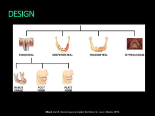
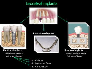
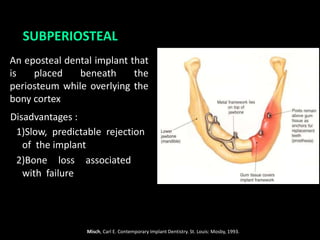
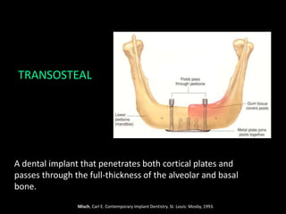
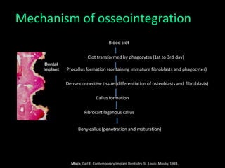
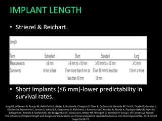
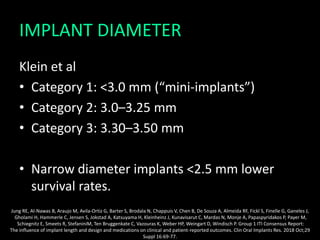
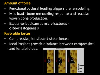
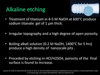
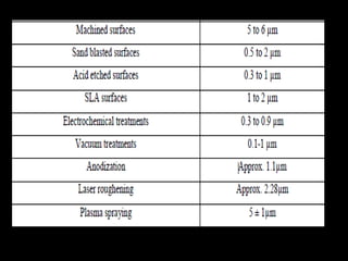
The document discusses various aspects of implant design and surface modifications. It describes different types of implant designs including endosteal, subperiosteal, and transosteal implants. Key factors in implant design discussed include length, diameter, geometry, and surface characteristics. Surface modifications aim to increase roughness and bioactivity through techniques like sandblasting, acid etching, and anodization. The goal is to enhance osteoblast adhesion and bone integration through both macroscale and microscale surface modifications.
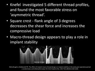
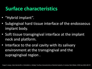
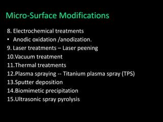


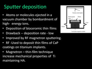
![Titanium Plasma Spray (TPS)
• Created by having an electrical arc.
• Finger-type tungsten cathode and nozzle-type
copper anode inside the plasma torch.
• Inject titanium powders into a plasma torch at high
temperature.
• Ti particles projected on to the surface of the
implants where they condense and fuse together,
forming a film about 30μm thick.
Amarante ES, de Lima LA. [Optimization of implant surfaces: titanium plasma spray and acid-etched sandblasting -- current status]. Pesqui
Odontol Bras. 2001 Apr-Jun;15(2):166-73](https://image.slidesharecdn.com/seminar-200824102212/85/Implant-design-59-320.jpg)
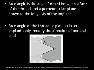
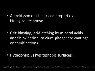
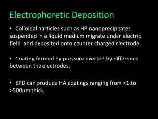
![• The thickness must reach 40-50μm to be uniform.
• TPS average roughness of around 7μm.
Amarante ES, de Lima LA. [Optimization of implant surfaces: titanium plasma spray and acid-etched sandblasting -- current status]. Pesqui
Odontol Bras. 2001 Apr-Jun;15(2):166-73](https://image.slidesharecdn.com/seminar-200824102212/85/Implant-design-60-320.jpg)
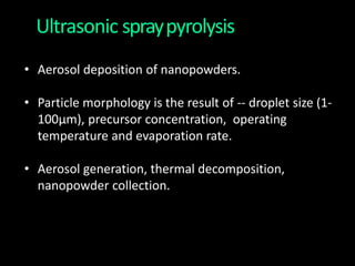
![• Amarante ES, de Lima LA. [Optimization of implant surfaces:
titanium plasma spray and acid-etched sandblasting -- current
status]. Pesqui Odontol Bras. 2001 Apr-Jun;15(2):166-73 .
• Al Mugeiren OM, Baseer MA. Dental Implant Bioactive Surface
Modifiers: An Update. J Int Soc Prev Community Dent. 2019
Jan-Feb;9(1):1-4.](https://image.slidesharecdn.com/seminar-200824102212/85/Implant-design-71-320.jpg)


![NEW dental implant design [Autosaved].pptx](https://cdn.slidesharecdn.com/ss_thumbnails/newimplantdesignautosaved-250614065418-013f8c1f-thumbnail.jpg?width=640&height=640&fit=bounds)


