Downloaded 36 times


![MATHEMATICAL MODELLING
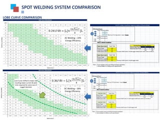
SPOT WELDING SYSTEM COMPARISON
Spot Welding Parameters Basic Calculation
𝐸 = 0.241𝑃𝑡w .........................(1) where E : Energy (J)
*Calculation for AC spot welding P : Power (W)
tw : Weld time (sec)
= 0.241𝐼2 𝑅𝑡w .........................(2) where I : Welding Current (A)
R : Panel Contact Resistance (Ω)
= JvSL .........................(3) where Jv : Melting energy (J/mm3
)
S : Surface contact (mm2
)
L : Total plate thickness combination (mm)
= Jv[π
𝑑2
4
]L ........................(4) where d : Required nugget diameter (mm)
Since 𝑑 = 4 𝑡min for general spot point
= 5 𝑡min for important spot point
Where 𝑡min : Min thickness of panel combinations
So, 0.241𝐼2 𝑅𝑡 = Jv[π
(4 𝑡min)2
4
]L .......(5) Combination eqn (2) & eqn (4)
= Jv[π4𝑡min]]L .............(6)
Final equation;
𝐼 =
Jv[π4𝑡min]]L
0.241𝑅𝑡w
2
..............(7) *Used for minimum nugget diameter requirement (general)
=
Jv[π
𝑑2
4
]L
0.241𝑅𝑡w
2
....................(8) *Used for specific required nugget diameter
Note :
Steel type Melting Energy Contact Resistance
Low Carbon Steel 9.7 J/mm3
100 μΩ
Aluminum 2.9 J/mm3
75 μΩ
Replace 𝐸 = 0.241𝑃𝑡w to 𝐸 = 0.37𝑃𝑡w for MFDC / DC spot welding calculation
𝐹w = 250𝑡min .............................(9) where 𝐹w = Welding Force (kg) - target
*Go to Quadratic approximation for best data fitting (refer reference) – No 11
𝑡w = 10𝑡min .............................(10) where 𝑡w = Weld time (cycle) – 50 hz
𝑡hold = 3 ~ 5 𝑐𝑦𝑐𝑙𝑒𝑠.................... where 𝑡hold = Hold time (cycle) – 50 hz
*𝑡squeeze - Pneumatic Gun : Min 17 cycle – Min time require for applied force to stable at 80%
- Servo Gun (robot) : 0 cycles – Using integrated robot function (robot will send
signal once applied force is stable to welding
controller)
Servo Gun : 4 cycle – Min time require for applied force to stable](https://image.slidesharecdn.com/dcacspotwelding-170213004525/85/DC-vs-AC-spot-welding-A-comparison-4-320.jpg)

This document compares different spot welding systems: DC, AC transformer gun, and AC portable gun. It finds that the DC system provides more stable weld quality, higher power/utilities savings due to a higher power factor and energy efficiency. The DC welding transformer is smaller in size and weight compared to the AC transformer gun. Mathematical equations are also presented for calculating welding parameters like current and time based on factors like material properties, plate thickness, and required nugget size.


![DESIGN AND FABRICATION OF THE IBM 90-90 SEAT BELT CLAMP KIA VEHICLE[1].pptx 2...](https://cdn.slidesharecdn.com/ss_thumbnails/designandfabricationoftheibm90-90seatbeltclampkiavehicle1-260116160442-70ff67fc-thumbnail.jpg?width=640&height=640&fit=bounds)


