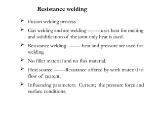
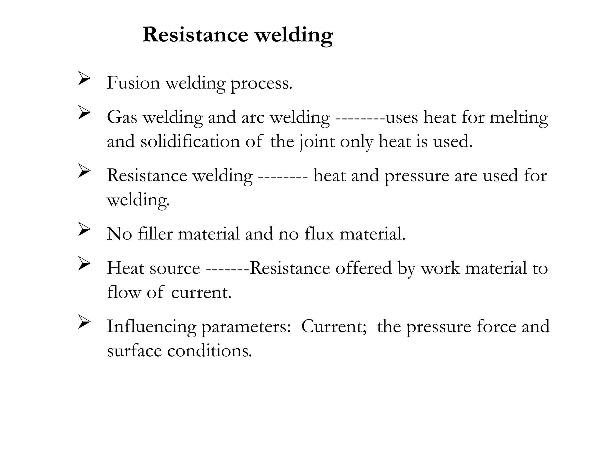
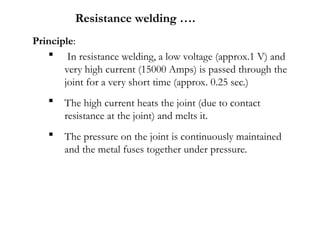
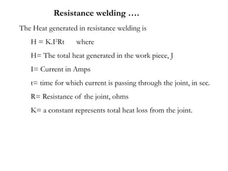
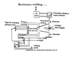
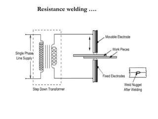
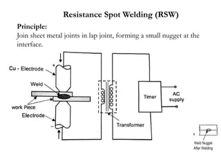
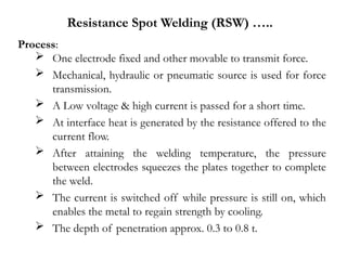
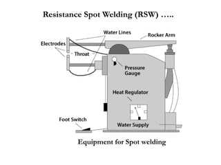
 Fusion welding process.
 Gas welding and arc welding --------uses heat for melting
and solidification of the joint only heat is used.
 Resistance welding -------- heat and pressure are used for
welding.
 No filler material and no flux material.
 Heat source -------Resistance offered by work material to
flow of current.
 Influencing parameters: Current; the pressure force and
surface conditions.
Resistance welding
Principle:
 In resistance welding, a low voltage (approx.1 V) and
very high current (15000 Amps) is passed through the
joint for a very short time (approx. 0.25 sec.)
 The high current heats the joint (due to contact
resistance at the joint) and melts it.
 The pressure on the joint is continuously maintained
and the metal fuses together under pressure.
Resistance welding ….
The Heat generated in resistance welding is
H = K.I2
Rt where
H= The total heat generated in the work piece, J
I= Current in Amps
t= time for which current is passing through the joint, in sec.
R= Resistance of the joint, ohms
K= a constant represents total heat loss from the joint.
Resistance welding ….
 Low voltage, high current is supplied. AC with step
down transformer is used.
 Time should be precisely controlled.
 The pressure (force) can be applied by mechanical,
hydraulic or pneumatic means.
Heat balance:
For smaller thickness ------- smaller contact area
For larger thickness -----------larger contact area.
For different materials (different thermal conductivity).
The heat liberated in the lowest resistivity material is less i,e.,
use of electrode of large contact area near the metal which
has higher electrical conductivity.
Resistance welding ….
Desired properties of electrodes
 Good electrical and thermal conductivity.
 Good mechanical strength.
Electrode Materials:
Copper - Cadmium (0.5 to 1.0%) ---for welding non ferrous
metals
Copper - Chromium (0.5 to 0.8%) ---for mild steel and low alloy
steel
Copper - Cobalt -Beryllium ----for stainless steel, tungsten and
other alloy steels.
Electrodes for resistance welding
Functions of electrode
 To carry high current
 To transmit mechanical force
 To keep the plates in alignment during welding
Resistance welding ….
Electrode tip shapes
Different shapes for different welding situations.
Pointed
Flat
Dome
Eccentric
Spherical
Other
Normally electrodes are air cooled water cooled.
Resistance welding ….
Advantages
 Easily Automated
 Suitable for mass
production
 Dissimilar metals can be
welded.
 Different thickness metals
can be welded.
 Less distortion as heating is
confined to less area.
Applications
 For thin sheets
 Automobile and aerospace industries
 For Carbon steel, stainless steel and nickel alloys.
Disadvantages.
 High cost. Economical
only for mass production.
 Thicker materials difficult
to weld.
 Large capacity machines
required.
 Sophisticated controls.
Resistance welding ….
Types of Resistance welding processes
 Resistance Spot welding
 Resistance Seam welding
 Projection welding
 Upset welding
 Flash welding
 Percussion welding
Resistance welding ….
Principle:
Join sheet metal joints in lap joint, forming a small nugget at the
interface.
Resistance Spot Welding (RSW)
Process:
 One electrode fixed and other movable to transmit force.
 Mechanical, hydraulic or pneumatic source is used for force
transmission.
 A Low voltage & high current is passed for a short time.
 At interface heat is generated by the resistance offered to the
current flow.
 After attaining the welding temperature, the pressure
between electrodes squeezes the plates together to complete
the weld.
 The current is switched off while pressure is still on, which
enables the metal to regain strength by cooling.
 The depth of penetration approx. 0.3 to 0.8 t.
Resistance Spot Welding (RSW) …..
Equipment for Spot welding
Process : Sequence of events
 Squeeze Time -----Align and clamp the work piece.
 Weld Time -------- Current flow.
 Hold Time --------- Pressure is maintained without current.
 Off Time ----------Pressure is taken off. Plates will be
moved for next spot.
Resistance Spot Welding (RSW) …..
Advantages
 All metals can be welded.
 No special care. Need only cleaning of weld surfaces.
 No filler metal and no edge preparation.
 High rate of production. (High speeds).
Disadvantages
 Only lap joints are possible.
 Not suitable for thicker metals (up to 6 mm max.)
 No leak proof.
 Indentation on sheets.
Applications
 For MS, SS, Al, Cu & Ni alloys.
 For dissimilar metals.
 Automobile bodies, refrigerator shelves, making boxes &
containers.
Resistance Spot Welding (RSW) …..
 Continuous spot welding process.
 Disc electrodes are used instead of cylindrical electrodes.
Sheets are allowed to pass between two copper discs
(Wheel-shaped) electrodes.
 Discs are rotated by an electric motor and the work is
moved between them.
 The current is applied in a series of pulses at proper
intervals.
 The timing is adjusted so that the pulses are either overlap
with each other or does not overlap making intermittent
nuggets.
Resistance Seam Welding (RSEW)
Resistance Seam Welding (RSEW) ….
Advantages
 Leak proof joints.
 Independent control of weld time and speed of
electrode wheels.
Disadvantages
 Only for thin metals (up to 5 mm)
 Higher currents and electrode pressure as compared to
spot welding
 Indentations (electrode marks).
Applications
 For welding Ms, Al, Mg and Ni alloys.
 For making flanges for watertight tanks.
 For seam welding of pipes, fabrication of tanks etc.
Resistance Seam Welding (RSEW) ….
 In spot and seam welding, current concentration at the
interface is achieved by shaping the electrodes and
restricting the contact area, whereas, in projection welding
the weld is located by projections raised on the surface of
one of the sheets.
 When overlapped together, the two sheets touch only at the
point of projections.
 When current is passed between the electrodes, the
projections collapse under the electrode pressure and sheets
are welded.
 Up to 6 projections are welded at the same time.
Resistance Projection Welding (RPW)
Resistance Projection Welding (RPW) ….
Advantages
 Longer electrode life (Due to large contact area).
 No electrode marks on work surface. No need of
painting or polishing.
 Less chances of distortion around the weld area.
 Suitable for thick plates.
 Proper heat balance can be made by making
projections in thicker sheets.
 Possible to weld more than one spot at a given time.
Resistance Projection Welding (RPW) ….
Disadvantages
 Prior operation of embossing (making projections) is
required.
 Only suitable for strong metals (which can withstand
electrode pressure on projections) i.e., copper, brass are not
suitable as projections cannot withstand.
Applications
 Car bodies, office furniture, machine parts.
 For SS, G.I and CS
Resistance Projection Welding (RPW) ….
 In this process, the two pieces to be joined are brought
together to join with each other in butt joint.
 These two pieces are held together tightly and current is
applied.
 The heat generated will bring the interfaces into plastic
state, then the current is off and two parts are pressed
together with upsetting force.
 Upsetting removes the surface impurities and allows to
form homogeneous joint.
Upset welding
Upset welding ….
Advantages
 No melting of the metal. Hence no spatter.
Disadvantages
 Non uniform heat distribution.
 For smaller areas.
Applications
 For joining small ferrous and nonferrous strips
 The process is suitable for welding small wires, pipes,
strips and copper tubes.
Upset welding …..
 Similar to upset welding except that the heat required
for melting is obtained by means of arc rather than
the simple resistance heating.
 Consists fixed and movable platen.
 The two plates are brought together and power
supply is switched on.
 The two pieces are then separated to create the arc to
melt the ends of the two pieces.
 Then, again the two pieces are brought together and
the power is switched off. The two ends are fused
together under force.
 Most of the metal melted will flash out through the
joint and forms like a fin around the joint.
Flash welding
Flash welding ….
Advantages
 No edge preparation is required.
 Faster than other processes.
 Larger cross sectional area can be joined (2500
mm2).
Disadvantages
 Not suitable for CI, Pb, Zn alloys.
Applications
 For sheets, rods, wires and tubes.
 In automotive and aircraft products.
Flash welding ….
 Similar to upset welding in which the welding is completed
in a short time with a high intensity arc between two parts.
 Arc is struck between work surfaces and melt the joint.
 The molten surfaces are then squeezed by impacting of
the work pieces forcing part of the liquid metal from the
joint to go outside.
 Further movement of the movable part applies percussion
force and makes it solidify under pressure.
 Used for small surface areas only (1 mm dia. wires), small
rods, tubes etc.
Percussion welding
Percussion welding ….
THANK YOU

Unit 3 & 4 Chapter 7 Resistance welding.pptx

  • 1.
     Fusion weldingprocess.  Gas welding and arc welding --------uses heat for melting and solidification of the joint only heat is used.  Resistance welding -------- heat and pressure are used for welding.  No filler material and no flux material.  Heat source -------Resistance offered by work material to flow of current.  Influencing parameters: Current; the pressure force and surface conditions. Resistance welding
  • 2.
    Principle:  In resistancewelding, a low voltage (approx.1 V) and very high current (15000 Amps) is passed through the joint for a very short time (approx. 0.25 sec.)  The high current heats the joint (due to contact resistance at the joint) and melts it.  The pressure on the joint is continuously maintained and the metal fuses together under pressure. Resistance welding ….
  • 3.
    The Heat generatedin resistance welding is H = K.I2 Rt where H= The total heat generated in the work piece, J I= Current in Amps t= time for which current is passing through the joint, in sec. R= Resistance of the joint, ohms K= a constant represents total heat loss from the joint. Resistance welding ….
  • 4.
  • 5.
  • 6.
     Low voltage,high current is supplied. AC with step down transformer is used.  Time should be precisely controlled.  The pressure (force) can be applied by mechanical, hydraulic or pneumatic means. Heat balance: For smaller thickness ------- smaller contact area For larger thickness -----------larger contact area. For different materials (different thermal conductivity). The heat liberated in the lowest resistivity material is less i,e., use of electrode of large contact area near the metal which has higher electrical conductivity. Resistance welding ….
  • 7.
  • 8.
    Desired properties ofelectrodes  Good electrical and thermal conductivity.  Good mechanical strength. Electrode Materials: Copper - Cadmium (0.5 to 1.0%) ---for welding non ferrous metals Copper - Chromium (0.5 to 0.8%) ---for mild steel and low alloy steel Copper - Cobalt -Beryllium ----for stainless steel, tungsten and other alloy steels. Electrodes for resistance welding Functions of electrode  To carry high current  To transmit mechanical force  To keep the plates in alignment during welding Resistance welding ….
  • 9.
    Electrode tip shapes Differentshapes for different welding situations. Pointed Flat Dome Eccentric Spherical Other Normally electrodes are air cooled water cooled. Resistance welding ….
  • 10.
    Advantages  Easily Automated Suitable for mass production  Dissimilar metals can be welded.  Different thickness metals can be welded.  Less distortion as heating is confined to less area. Applications  For thin sheets  Automobile and aerospace industries  For Carbon steel, stainless steel and nickel alloys. Disadvantages.  High cost. Economical only for mass production.  Thicker materials difficult to weld.  Large capacity machines required.  Sophisticated controls. Resistance welding ….
  • 11.
    Types of Resistancewelding processes  Resistance Spot welding  Resistance Seam welding  Projection welding  Upset welding  Flash welding  Percussion welding Resistance welding ….
  • 12.
    Principle: Join sheet metaljoints in lap joint, forming a small nugget at the interface. Resistance Spot Welding (RSW)
  • 13.
    Process:  One electrodefixed and other movable to transmit force.  Mechanical, hydraulic or pneumatic source is used for force transmission.  A Low voltage & high current is passed for a short time.  At interface heat is generated by the resistance offered to the current flow.  After attaining the welding temperature, the pressure between electrodes squeezes the plates together to complete the weld.  The current is switched off while pressure is still on, which enables the metal to regain strength by cooling.  The depth of penetration approx. 0.3 to 0.8 t. Resistance Spot Welding (RSW) …..
  • 14.
    Resistance Spot Welding(RSW) ….. Equipment for Spot welding
  • 15.
    Process : Sequenceof events  Squeeze Time -----Align and clamp the work piece.  Weld Time -------- Current flow.  Hold Time --------- Pressure is maintained without current.  Off Time ----------Pressure is taken off. Plates will be moved for next spot. Resistance Spot Welding (RSW) …..
  • 16.
    Advantages  All metalscan be welded.  No special care. Need only cleaning of weld surfaces.  No filler metal and no edge preparation.  High rate of production. (High speeds). Disadvantages  Only lap joints are possible.  Not suitable for thicker metals (up to 6 mm max.)  No leak proof.  Indentation on sheets. Applications  For MS, SS, Al, Cu & Ni alloys.  For dissimilar metals.  Automobile bodies, refrigerator shelves, making boxes & containers. Resistance Spot Welding (RSW) …..
  • 17.
     Continuous spotwelding process.  Disc electrodes are used instead of cylindrical electrodes. Sheets are allowed to pass between two copper discs (Wheel-shaped) electrodes.  Discs are rotated by an electric motor and the work is moved between them.  The current is applied in a series of pulses at proper intervals.  The timing is adjusted so that the pulses are either overlap with each other or does not overlap making intermittent nuggets. Resistance Seam Welding (RSEW)
  • 18.
  • 19.
    Advantages  Leak proofjoints.  Independent control of weld time and speed of electrode wheels. Disadvantages  Only for thin metals (up to 5 mm)  Higher currents and electrode pressure as compared to spot welding  Indentations (electrode marks). Applications  For welding Ms, Al, Mg and Ni alloys.  For making flanges for watertight tanks.  For seam welding of pipes, fabrication of tanks etc. Resistance Seam Welding (RSEW) ….
  • 20.
     In spotand seam welding, current concentration at the interface is achieved by shaping the electrodes and restricting the contact area, whereas, in projection welding the weld is located by projections raised on the surface of one of the sheets.  When overlapped together, the two sheets touch only at the point of projections.  When current is passed between the electrodes, the projections collapse under the electrode pressure and sheets are welded.  Up to 6 projections are welded at the same time. Resistance Projection Welding (RPW)
  • 21.
  • 22.
    Advantages  Longer electrodelife (Due to large contact area).  No electrode marks on work surface. No need of painting or polishing.  Less chances of distortion around the weld area.  Suitable for thick plates.  Proper heat balance can be made by making projections in thicker sheets.  Possible to weld more than one spot at a given time. Resistance Projection Welding (RPW) ….
  • 23.
    Disadvantages  Prior operationof embossing (making projections) is required.  Only suitable for strong metals (which can withstand electrode pressure on projections) i.e., copper, brass are not suitable as projections cannot withstand. Applications  Car bodies, office furniture, machine parts.  For SS, G.I and CS Resistance Projection Welding (RPW) ….
  • 24.
     In thisprocess, the two pieces to be joined are brought together to join with each other in butt joint.  These two pieces are held together tightly and current is applied.  The heat generated will bring the interfaces into plastic state, then the current is off and two parts are pressed together with upsetting force.  Upsetting removes the surface impurities and allows to form homogeneous joint. Upset welding
  • 25.
  • 26.
    Advantages  No meltingof the metal. Hence no spatter. Disadvantages  Non uniform heat distribution.  For smaller areas. Applications  For joining small ferrous and nonferrous strips  The process is suitable for welding small wires, pipes, strips and copper tubes. Upset welding …..
  • 27.
     Similar toupset welding except that the heat required for melting is obtained by means of arc rather than the simple resistance heating.  Consists fixed and movable platen.  The two plates are brought together and power supply is switched on.  The two pieces are then separated to create the arc to melt the ends of the two pieces.  Then, again the two pieces are brought together and the power is switched off. The two ends are fused together under force.  Most of the metal melted will flash out through the joint and forms like a fin around the joint. Flash welding
  • 28.
  • 29.
    Advantages  No edgepreparation is required.  Faster than other processes.  Larger cross sectional area can be joined (2500 mm2). Disadvantages  Not suitable for CI, Pb, Zn alloys. Applications  For sheets, rods, wires and tubes.  In automotive and aircraft products. Flash welding ….
  • 30.
     Similar toupset welding in which the welding is completed in a short time with a high intensity arc between two parts.  Arc is struck between work surfaces and melt the joint.  The molten surfaces are then squeezed by impacting of the work pieces forcing part of the liquid metal from the joint to go outside.  Further movement of the movable part applies percussion force and makes it solidify under pressure.  Used for small surface areas only (1 mm dia. wires), small rods, tubes etc. Percussion welding
  • 31.
  • 32.