Graphical approach representing a group of spot welding parameters setting that falls under body manufacturing requirements. Used to optimize parameters setting to reduce input energy & increase productivity ( increase consumables life span)
Resistance spot welding - impact of process parameters on weld nugget formationRashidi Asari
This article shows the relationship between spot welding parameters namely weld force, weld current and weld time & how they are inter related in weld nugget formation. Graphical lobe curve is used as presentation for better understanding. Lobe curve is very useful especially in spot welding process parameters optimization.
Resistance Spot Welding - Development of Simulation Tool for EngineersRashidi Asari
The development of graphical tool for welding engineers & technicians to select the optimized welding parameters that suit with sheet metal and equipment to be used at production line side.
Finite element modeling and bending stress analysis of non standard spur geareSAT Journals
Abstract Gears are toothed wheels, transmitting power and motion from one shaft to another by means of successive engagement of teeth. Having a higher degree of reliability, compactness, high velocity ratio and finally able to transmit motion at a very low velocity, gears are gaining importance as the most efficient means for transmitting power. A gearing system is susceptible to problems such as interference, backlash and undercut. The contact portions of tooth profiles that are not conjugate is called interference. Furthermore due to interference and in the absence of undercut, the involute tip or face of the driven gear tends to dig out the non-involute flank of the driver. The response of a spur gear and its wear is an engineering problem that has not been completely overcome yet. With the perspective of overcoming such defects and for increase the efficiency of gearing system, the use of a non-standard spur gear i.e., an asymmetric spur gear having different pressure angles for drive and coast side of the tooth comes into picture. This paper emphasis on the generation of an asymmetric spur gear tooth using modeling software and bending stress at the root of Asymmetric spur gear tooth is estimated by finite element analysis using ANSYS software and results were compared with the standard spur gear tooth. Keywords: Asymmetric spur gear, Bending stress, Finite element method, Pressure angle
Litrature review on numerical analysis on residual stress on plate guiderTEJASKRIYA PRADHAN
In weld, Large amount of heat is generated. For which near the welding zone some are experienced tension and some experienced compression.
That zone is called Heat Affected Zone(HAZ).
Investigation of Effect of Process Parameters on Maximum Temperature during F...IJSRD
In case of friction stir welding, the maximum temperature along the weld line within appropriate range at tool workpiece interface is responsible for quality of welded joint. Through this paper, an attempt is made to establish a relationship between the input process parameters and the maximum temperature along the weld line during friction stir welding of aluminium alloy AA-7075. The design of pre-experimental simulation has been performed in accordance with full factorial technique. The simulation of friction stir welding has been performed by varying input parameters, tool rotational speed and welding speed. The analysis of variance (ANOVA) is used to investigate the effect of input parameters on maximum temperature during friction stir welding. A correlation was established between input parameters and maximum temperature by multiple regression lines. This study indicates that the tool rotational speed is the main input parameter that has high statistical influence on maximum temperature along the weld line during friction stir welding of aluminium alloy AA-7075.
TENSILE BEHAVIOUR OF ALUMINIUM PLATES (5083) WELDED BY FRICTION STIR WELDING IAEME Publication
Using arc welding, gas welding and other welding process, it is very difficult to weld the aluminum alloys. Friction stir welding, on the other hand, can be used to join most Al alloys and
better surface finishing is achieved. Although the work piece does heat up during friction stir weld, the temperature does not reach the melting point.
Modeling and Simulation of Base Plate of Friction Stir Welding-Advanced Weldi...ijsrd.com
Friction stir processing is an emerging technique based on the principles of friction stir welding (FSW). It is a solid-state joining method that is energy efficient, environmentally friendly, and versatile. It is considered by many to be the most significant development in metal joining in a decade. The basic concept of friction stir processing is remarkably simple. A rotating tool with pin and shoulder is inserted in the material to be joined, and traversed along the line of interest. The heating is localized, and is generated by friction between the tool and the work piece, with additional adiabatic heating from metal deformation. A processed zone is produced by movement of material from the front of the pin to the back of the pin.
Design and Analysis of Connecting Rod of Diesel Engineijtsrd
The main objective of this study is to review the weight optimization and cost reduction of a connecting rod in a Diesel engine. To get the idea about designing the connecting rod, various stresses to be considered while designing the connecting rod .This has entailed performing a detailed load analysis. The most important factors that are concentrated are stress distribution and deflections. In this project the connecting rod is designed with respect to all the available constraints using advanced cad software CATIA. Later the product file is converted to .stp file format standard exchange of product file and imported to ANSYS workbench to find deformation and analytic valve with respect to the model or product definitions. A. Vijay Kumar | K. Mihir | M. Mrudul | P. Pavan Kumar ""Design and Analysis of Connecting Rod of Diesel Engine"" Published in International Journal of Trend in Scientific Research and Development (ijtsrd), ISSN: 2456-6470, Volume-3 | Issue-3 , April 2019, URL: https://www.ijtsrd.com/papers/ijtsrd23182.pdf
Paper URL: https://www.ijtsrd.com/engineering/mechanical-engineering/23182/design-and-analysis-of-connecting-rod-of-diesel-engine/a-vijay-kumar
A REVIEW ON OPTIMIZATION OF RESISTANCE SPOT WELDING OF ALUMINUM COMPONENTS US...AM Publications
Resistance Spot welding (RSW) is one of the common welding processes used for sheet joining especially in the automobile and aerospace industry. It is used in a wide range of industries but notably for the assembly of sheet steel vehicle bodies. This is a type of resistance welding where the spot welds are made at regular intervals on overlapping sheets of metal. Spot welding is primarily used for joining parts that are normally up to 3 mm in thickness. The joint quality can be defined in terms of properties such as weld-bead geometry, mechanical properties and distortion.The objective of the research is to determine the optimum combination of parameters responsible for better quality of joints. The complicated behavior of the process must be analyzed to set the optimum parameters to get the optimum weld quality. The paper also presents the FEA simulation of the RSW process.
Study of Simulated Temperature of Butt Joint during Friction Stir Welding Of ...IJERA Editor
Friction stir welding (FSW) is one of the latest welding technology that utilizes a special tool for generation of frictional heat in the work piece by its rotation due to which joining occurs without melting of metal. For this reason friction stir welding lies under the category of solid state joining. A part from experimental work, there is large space to work on simulation of FSW by using simulation tools. In the present paper, simulation of friction stir welding of aluminium alloy AA-6061 is done by using HyperWeld module of Altair HyperWorks. The virtual experiment of friction stir welding is conducted for variable tool rotational speeds with constant travelling speed and study of simulation results of variation in temperature distribution along the weld line of butt joint is done. The results of simulation shows that the temperature is symmetrically distributed along the weld line. It is observed that the maximum temperature along the weld line increases with the increase in rotational speed. It is also observed that the temperature at advancing side is greater that retreating side.
An Experimental Study to Predict Optimum Weld Bead Geometry through Effect of...IJMER
International Journal of Modern Engineering Research (IJMER) is Peer reviewed, online Journal. It serves as an international archival forum of scholarly research related to engineering and science education.
International Journal of Modern Engineering Research (IJMER) covers all the fields of engineering and science: Electrical Engineering, Mechanical Engineering, Civil Engineering, Chemical Engineering, Computer Engineering, Agricultural Engineering, Aerospace Engineering, Thermodynamics, Structural Engineering, Control Engineering, Robotics, Mechatronics, Fluid Mechanics, Nanotechnology, Simulators, Web-based Learning, Remote Laboratories, Engineering Design Methods, Education Research, Students' Satisfaction and Motivation, Global Projects, and Assessment…. And many more.
Weld Improvement Example in Offshore Oil & GasImran Choudury
Weld improvement examples in offshore oil and gas platforms. Professional training courses in the energy industry, Methods to manage corrosion and crack growth. Where to perform grinding by a burr grinder?
Simulation of Deep-Drawing Process of Large Panelstheijes
The article deals with the analysis of formability of deep-drawing DC06 steel sheets. The aim of the investigations is to verify possibilities of formability of sheet metal with thickness of 0.85 mm. The mechanical parameters of the sheets have been determined in uniaxial tensile and bulge tests. The numerical simulations using AUTOFORM has been carried out for two drawpiece models. Obtained results can be used during the simulation of real forming process.
Multiphysics Modeling of Induction Machines_Jd'12 presMellah Hacene
in this paper we interest to how we can validate simultaneously a thermal model and estimated variable of induction motor. This approach is possible by using special simulation package frequently exploited bout in university and industry. A simple description of each one of this famous software is presented.
According to our needs and means; I took a justified choice of the used software in this validation context. In this moment, I make
only the modeling of an induction machine without takes into account the heating effects. Same simulation results of induction
motor model by Maxwell software is given and commented.
Resistance Spot Welding - Process Optimization using Lobe Curve GeneratorRashidi Asari
In spot welding process, process parameters optimization means improve spot welding quality while reduce operational cost especially power consumption and welding consumables. Lobe curve generators may assist welding engineers and technicians to select the best welding parameters according to their requirements.
“Laser Cutting of weldox-700 materials is popular processes in manufacturing industries This research paper for primary study for evaluate the effect of the processing parameters (Laser Power, gas pressure, pulse frequency and Cutting speed) under the quality of the cut for weldox-700 materials. Then the experiment was done by 6mm thick weldox-700 material plates. In this experiment focused on establish relation of different parameters on Cutting quality, which is decided by the Surface Roughness and Kerf Width.
Inspired by Automated Guided Vehicle (AGV) concepts, the 'Automated Guided Dolly' is designed, fabricated & programmed to carry the total load of 750kg (body + dolly) and transfer body from starting point to the next point. Then, the empty dolly will go back to the starting point once the body is delivered.
Explore the innovative world of trenchless pipe repair with our comprehensive guide, "The Benefits and Techniques of Trenchless Pipe Repair." This document delves into the modern methods of repairing underground pipes without the need for extensive excavation, highlighting the numerous advantages and the latest techniques used in the industry.
Learn about the cost savings, reduced environmental impact, and minimal disruption associated with trenchless technology. Discover detailed explanations of popular techniques such as pipe bursting, cured-in-place pipe (CIPP) lining, and directional drilling. Understand how these methods can be applied to various types of infrastructure, from residential plumbing to large-scale municipal systems.
Ideal for homeowners, contractors, engineers, and anyone interested in modern plumbing solutions, this guide provides valuable insights into why trenchless pipe repair is becoming the preferred choice for pipe rehabilitation. Stay informed about the latest advancements and best practices in the field.
Saudi Arabia stands as a titan in the global energy landscape, renowned for its abundant oil and gas resources. It's the largest exporter of petroleum and holds some of the world's most significant reserves. Let's delve into the top 10 oil and gas projects shaping Saudi Arabia's energy future in 2024.
Water scarcity is the lack of fresh water resources to meet the standard water demand. There are two type of water scarcity. One is physical. The other is economic water scarcity.
Cosmetic shop management system project report.pdfKamal Acharya
Buying new cosmetic products is difficult. It can even be scary for those who have sensitive skin and are prone to skin trouble. The information needed to alleviate this problem is on the back of each product, but it's thought to interpret those ingredient lists unless you have a background in chemistry.
Instead of buying and hoping for the best, we can use data science to help us predict which products may be good fits for us. It includes various function programs to do the above mentioned tasks.
Data file handling has been effectively used in the program.
The automated cosmetic shop management system should deal with the automation of general workflow and administration process of the shop. The main processes of the system focus on customer's request where the system is able to search the most appropriate products and deliver it to the customers. It should help the employees to quickly identify the list of cosmetic product that have reached the minimum quantity and also keep a track of expired date for each cosmetic product. It should help the employees to find the rack number in which the product is placed.It is also Faster and more efficient way.
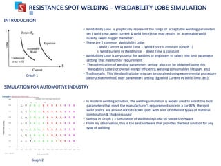
1. RESISTANCE SPOT WELDING – WELDABILITY LOBE SIMULATION
INTRODUCTION
• Weldability Lobe is graphically represent the range of acceptable welding parameters
set ( weld time, weld current & weld force) that may results in acceptable weld
quality (weld nugget diameter)
• There are 2 common Weldability Lobe:
i. Weld Current vs Weld Time - Weld Force is constant (Graph 1)
ii. Weld Current vs Weld Force - Weld Time is constant
• Weldability Lobe is very useful for welders or engineers to select the best parameter
setting that meets their requirement
• The optimization of welding parameters setting also can be obtained using this
Weldability Lobe (for overall energy efficiency, welding consumables lifespan, etc)
• Traditionally, This Weldability Lobe only can be obtained using experimental procedure
(destructive method) over parameters setting (Eg Weld Current vs Weld Time..etc)
Graph 1
SIMULATION FOR AUTOMOTIVE INDUSTRY
Graph 2
• In modern welding activities, the welding simulation is widely used to select the best
parameters that meet the manufacturer’s requirement since in a car BIW, the spot
weld points are around 4000 to 6000 spots with a lot of different types of material
combination & thickness used
• Sample in Graph 2 – Simulation of Weldability Lobe by SORPAS software
• From my observation, this is the best software that provides the best solution for any
type of welding
2. RESISTANCE SPOT WELDING – WELDABILITY LOBE SIMULATION
•
SIMULATION FOR AUTOMOTIVE INDUSTRY (SIMPLIFIED)
kg
450 2.4 2.6 2.9 3.1 3.3 3.5 3.7 4.0 4.2 4.4 4.6 4.8 5.1 5.3 5.5 5.7
425 2.5 2.7 2.9 3.2 3.4 3.6 3.9 4.1 4.3 4.5 4.8 5.0 5.2 5.4 5.7 5.9
400 2.6 2.8 3.0 3.3 3.5 3.7 4.0 4.2 4.4 4.7 4.9 5.1 5.4 5.6 5.8 6.1
375 2.7 2.9 3.1 3.4 3.6 3.9 4.1 4.3 4.6 4.8 5.1 5.3 5.6 5.8 6.0 6.3
350 2.7 3.0 3.2 3.5 3.7 4.0 4.2 4.5 4.7 5.0 5.2 5.5 5.7 6.0 6.2 6.5
325 2.9 3.1 3.4 3.6 3.9 4.1 4.4 4.7 4.9 5.2 5.4 5.7 6.0 6.2 6.5 6.7
300 3.0 3.2 3.5 3.8 4.0 4.3 4.6 4.9 5.1 5.4 5.7 5.9 6.2 6.5 6.7 7.0
275 3.1 3.4 3.7 3.9 4.2 4.5 4.8 5.1 5.4 5.6 5.9 6.2 6.5 6.8 7.0 7.3
250 3.3 3.5 3.8 4.1 4.4 4.7 5.0 5.3 5.6 5.9 6.2 6.5 6.8 7.1 7.4 7.7
225 3.4 3.7 4.1 4.4 4.7 5.0 5.3 5.6 5.9 6.2 6.5 6.9 7.2 7.5 7.8 8.1
200 3.6 4.0 4.3 4.6 5.0 5.3 5.6 5.9 6.3 6.6 6.9 7.3 7.6 7.9 8.3 8.6
175 3.9 4.2 4.6 4.9 5.3 5.7 6.0 6.4 6.7 7.1 7.4 7.8 8.1 8.5 8.8 9.2
150 4.2 4.6 5.0 5.3 5.7 6.1 6.5 6.9 7.2 7.6 8.0 8.4 8.8 9.2 9.5 9.9
125 4.6 5.0 5.4 5.9 6.3 6.7 7.1 7.5 7.9 8.4 8.8 9.2 9.6 10.0 10.4 10.9
100 5.1 5.6 6.1 6.5 7.0 7.5 7.9 8.4 8.9 9.3 9.8 10.3 10.7 11.2 11.7 12.2
5,500 6,000 6,500 7,000 7,500 8,000 8,500 9,000 9,500 10,000 10,500 11,000 11,500 12,000 12,500 13,000 A
Lobe Curve (Simulation) - 2 Ply
WeldingForce,Kg
Weld Current, A
• In order to ease the simulation, The Weldability Lobe Simulator is
programmed using basic equations as shown in next slide. The
simulator may simulate different panels combination (types &
thickness) to predict the best welding parameters to be used
• This simulator also may predict the failure mode due to process
parameters (welding current & force fluctuation) from the graph
• Basically, the simulator may generates 2 types of graph as shown;
i. Weld Current vs Weld Time - Weld Force constant
ii. Weld Current vs Weld Force – Weld Time constant
• Physical confirmation at line side is required using test piece
(destruct) or NDT device (ultrasonic)
• From the test conducted from the past, the minimum 90%
accuracy is achieved (simulation vs actual)
Input Data (Sample)
3. 2
Where;
k : Energy Efficient Constant
I : Welding Current (A)
R : Panel Contact Resistance (Ω)
Jv : Melting energy (J/mm3
)
S : Surface contact (mm2
)
L : Total plate thickness combination (mm)
d : Required nugget diameter (mm)
RESISTANCE SPOT WELDING – BASIC CALCULATION
Equation:
Portable Spot Welding
Robot Spot Welding – Trans Gun
Parameters Value (Low carbon Steel)
Jv 9.7 J/mm3
R 0.1 mΩ
k
0.241 (Portable Spot Welding - AC)
0.29 (Trans Gun – AC)
0.37 (Trans Gun – DC)
F˳
Ratio : Fs / Fi
Where Fs (Setting weld force)
Fi (Ideal weld force for R = 0.1 mΩ) – Thickness dependant
(Fi(t))
1