The document discusses the basics of DC motors and generators. It covers topics like:
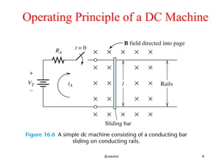
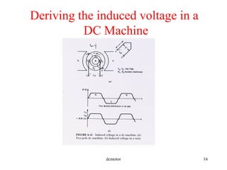
- The operating principles of DC machines and how they work as motors and generators.
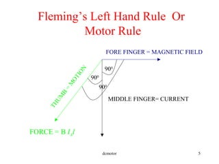
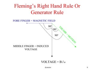
- Fleming's left and right hand rules for determining the direction of motion, induced voltage, and magnetic fields.
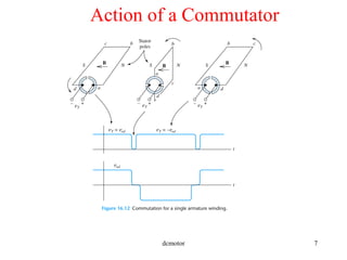
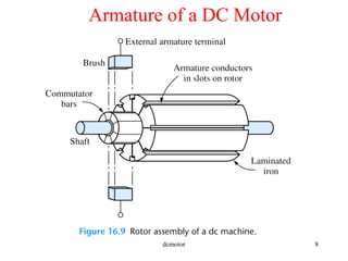
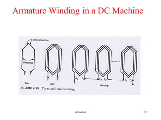
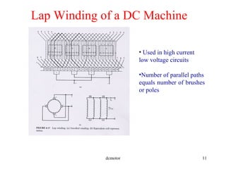
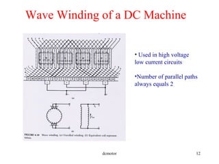
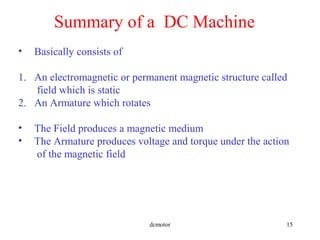
- Components of DC machines like the armature, field coils, commutators, and different winding configurations.
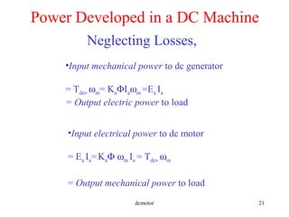
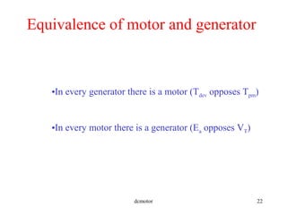
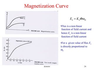
- How torque, speed, input power, and output power are related in DC motors and generators.
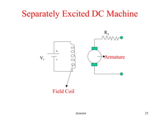
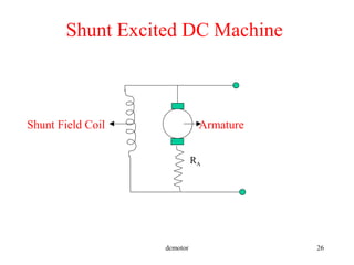
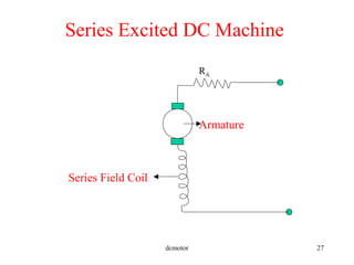
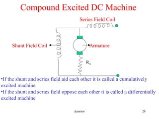
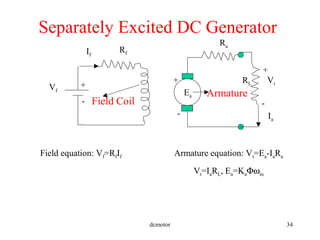
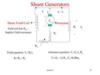
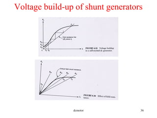
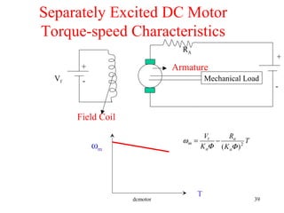
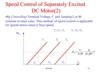
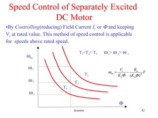
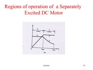
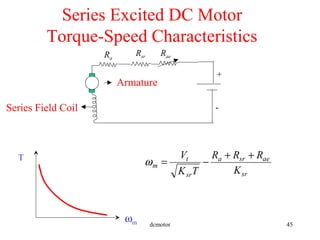
- Characteristics and speed control methods for separately excited, series, and shunt DC machines.
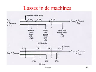
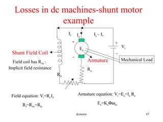
- Losses that occur in DC machines and examples of calculations related to voltage, current, torque


![Chapter 4 dc machine [autosaved]](https://cdn.slidesharecdn.com/ss_thumbnails/chapter4-dcmachineautosaved-140915220206-phpapp01-thumbnail.jpg?width=640&height=640&fit=bounds)


