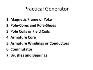
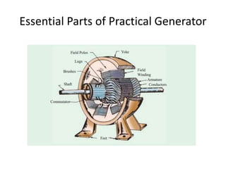
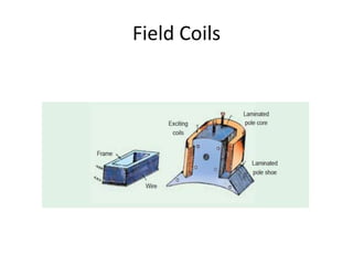
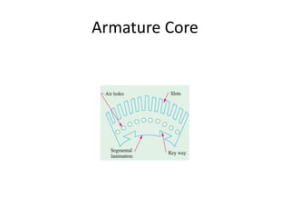
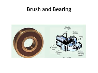
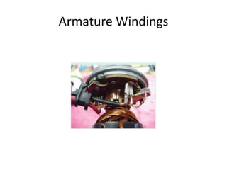
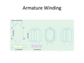
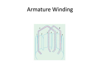
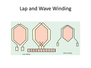
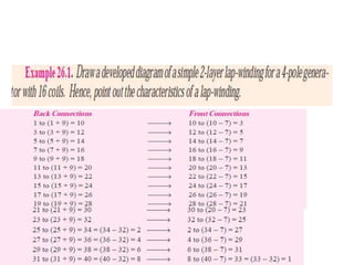
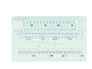
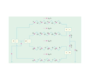
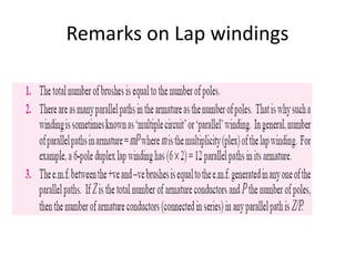
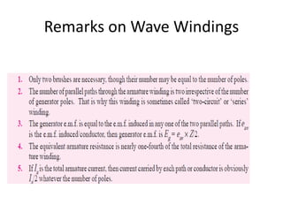
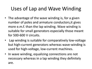
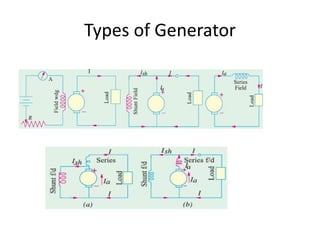
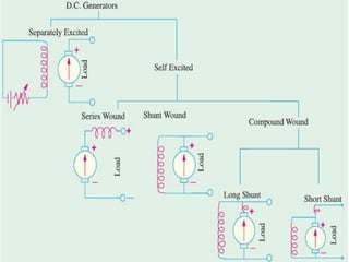
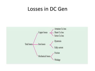
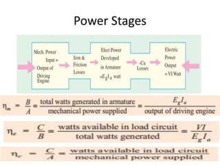
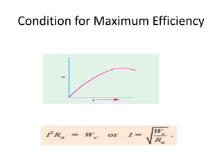
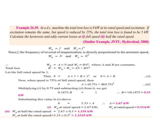
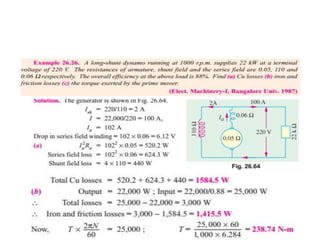
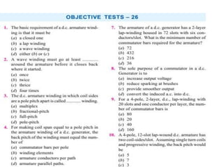
( Electrical Machine-1)
DC Generator
DC Motor
Introduction to Wind turbine Generator and Solar Cells
Transformer
3-Phase Transformer
Elements of Electromechanical
Conversion
• Prime movers convert some sources of energy into
mechanical energy that in turn converted to electrical
energy by Synchronous Generator
• Device has stator, rotor and airgap. For a flux path, the
magnetic circuit has three parts in series.
• Equal no of poles must be created on both sides
• A device can work either as a generator or as a motor
• They have electrical port ( armature terminals),
mechanical port ( Shaft) and coupling field ( magnetic
field or electric field)
• Energy Balance dWelec= DW mech + dWfield
Elements of Electromechanical
Conversion
Simple Loop Generator
Working of Loop Generator
Split Rings
Working with Split-Rings
Practical Generator
1. Magnetic Frame or Yoke
2. Pole-Cores and Pole-Shoes
3. Pole Coils or Field Coils
4. Armature Core
5. Armature Windings or Conductors
6. Commutator
7. Brushes and Bearings
Essential Parts of Practical Generator
Yoke and pole
Yoke
provides mechanical support for the poles and
acts as a protecting cover for the whole
machine
carries the magnetic flux produced by the
poles.
Pole Cores and Pole Shoes
• They spread out the flux in the air gap and
also, being of larger cross-section, reduce the
reluctance of the magnetic path
• They support the exciting coils (or field coils)
• In modern design, the complete pole cores and
pole shoes are built of thin laminations of
annealed steel which are riveted together
under hydraulic pressure . The thickness of
laminations varies from 1 mm to 0.25 mm.
Field Coils
Field Coils
• The field coils or pole coils, which consist of
copper wire or strip, are former-wound for the
correct dimension . Then, the former is
removed and wound coil is put into place over
the core
Armature core
Armature Core
• It houses the armature conductors or coils and
causes them to rotate and hence cut the
magnetic flux of the field magnets. In addition to
this, its most important function is to provide a
path of very low reluctance to the flux through
the armature from a N-pole to a S-pole.
• It is cylindrical or drum-shaped and is built up of
usually circular sheet steel discs or laminations
approximately 0.5 mm thick. It is keyed to the
shaft.
Armature Core
Armature Windings
• The armature windings are usually former-
wound.
Commutator
Commutator
• The function of the commutator is to facilitate
collection of current from the armature conductors.
• It converts the alternating current induced in the
armature conductors into unidirectional current in the
external load circuit. It is of cylindrical struc ture and
isbuilt up of wedge-shaped segments of copper.
• These segments are insulated from each other by thin
layers of mica. The number of segments is equal to the
number of armature coils. Each commutator segment
is connected to the armature conductor by means of a
copper lug or strip (or riser).
Brush and Bearing
Brushes and Bearings
• The brushes whose function is to collect current
from commutator, are usually made of carbon or
graphite and are in the shape of a rectangular
block. These brushes are housed in brush-holders
• Because of their reliability, ball-bearings are
frequently employed, though for heavy duties,
roller bearings are preferable. The ball and rollers
are generally packed in hard oil for quieter
operation.
Armature Windings
Armature Winding
Armature Winding
Front Pitch and Back Pitch
2-Layer Windings
Lap and Wave Winding
Remarks on Lap windings
Wave Winding
Remarks on Wave Windings
Uses of Lap and Wave Winding
• The advantage of the wave winding is, for a given
number of poles and armature conductors,it gives
more e.m.f. than the lap winding. Wave winding is
suitable for small generators especially those meant
for 500-600 V circuits.
• Lap winding is suitable for comparatively low-voltage
but high-current generators whereas wave-winding is
used for high-voltage, low-current machines.
• In wave winding, equalizing connections are not
necessary whereas in a lap winding they definitely
are.
Types of Generator
Hysteresis Loss and Eddy Current Loss
Losses in DC Gen
Power Stages
Condition for Maximum Efficiency
DC Generator
DC Generator
DC Generator

DC Generator

  • 1.
    ( Electrical Machine-1) DCGenerator DC Motor Introduction to Wind turbine Generator and Solar Cells Transformer 3-Phase Transformer
  • 2.
    Elements of Electromechanical Conversion •Prime movers convert some sources of energy into mechanical energy that in turn converted to electrical energy by Synchronous Generator • Device has stator, rotor and airgap. For a flux path, the magnetic circuit has three parts in series. • Equal no of poles must be created on both sides • A device can work either as a generator or as a motor • They have electrical port ( armature terminals), mechanical port ( Shaft) and coupling field ( magnetic field or electric field) • Energy Balance dWelec= DW mech + dWfield
  • 3.
  • 4.
  • 5.
    Working of LoopGenerator
  • 6.
  • 7.
  • 8.
    Practical Generator 1. MagneticFrame or Yoke 2. Pole-Cores and Pole-Shoes 3. Pole Coils or Field Coils 4. Armature Core 5. Armature Windings or Conductors 6. Commutator 7. Brushes and Bearings
  • 9.
    Essential Parts ofPractical Generator
  • 10.
  • 11.
    Yoke provides mechanical supportfor the poles and acts as a protecting cover for the whole machine carries the magnetic flux produced by the poles.
  • 12.
    Pole Cores andPole Shoes • They spread out the flux in the air gap and also, being of larger cross-section, reduce the reluctance of the magnetic path • They support the exciting coils (or field coils) • In modern design, the complete pole cores and pole shoes are built of thin laminations of annealed steel which are riveted together under hydraulic pressure . The thickness of laminations varies from 1 mm to 0.25 mm.
  • 13.
  • 14.
    Field Coils • Thefield coils or pole coils, which consist of copper wire or strip, are former-wound for the correct dimension . Then, the former is removed and wound coil is put into place over the core
  • 15.
  • 16.
    Armature Core • Ithouses the armature conductors or coils and causes them to rotate and hence cut the magnetic flux of the field magnets. In addition to this, its most important function is to provide a path of very low reluctance to the flux through the armature from a N-pole to a S-pole. • It is cylindrical or drum-shaped and is built up of usually circular sheet steel discs or laminations approximately 0.5 mm thick. It is keyed to the shaft.
  • 17.
  • 18.
    Armature Windings • Thearmature windings are usually former- wound.
  • 19.
  • 20.
    Commutator • The functionof the commutator is to facilitate collection of current from the armature conductors. • It converts the alternating current induced in the armature conductors into unidirectional current in the external load circuit. It is of cylindrical struc ture and isbuilt up of wedge-shaped segments of copper. • These segments are insulated from each other by thin layers of mica. The number of segments is equal to the number of armature coils. Each commutator segment is connected to the armature conductor by means of a copper lug or strip (or riser).
  • 21.
  • 22.
    Brushes and Bearings •The brushes whose function is to collect current from commutator, are usually made of carbon or graphite and are in the shape of a rectangular block. These brushes are housed in brush-holders • Because of their reliability, ball-bearings are frequently employed, though for heavy duties, roller bearings are preferable. The ball and rollers are generally packed in hard oil for quieter operation.
  • 23.
  • 24.
  • 25.
  • 26.
    Front Pitch andBack Pitch
  • 27.
  • 28.
    Lap and WaveWinding
  • 32.
  • 34.
  • 37.
  • 38.
    Uses of Lapand Wave Winding • The advantage of the wave winding is, for a given number of poles and armature conductors,it gives more e.m.f. than the lap winding. Wave winding is suitable for small generators especially those meant for 500-600 V circuits. • Lap winding is suitable for comparatively low-voltage but high-current generators whereas wave-winding is used for high-voltage, low-current machines. • In wave winding, equalizing connections are not necessary whereas in a lap winding they definitely are.
  • 39.
  • 46.
    Hysteresis Loss andEddy Current Loss
  • 47.
  • 48.
  • 49.