International Islamic UniversityH-10, Islamabad, Pakistan
Database Management System
Week 03
Data Models
and ER Diagram Model
Engr. Rashid Farid Chishti
http://youtube.com/rfchishti
http://sites.google.com/site/chisht
i
2.
Understand differenttypes of data models
Learn the components and uses of the Entity-Relationship (ER) model
Develop ER diagrams with entities, attributes, and relationships
Grasp the concept of cardinality and mapping constraints
Learning Objectives
3.
Data Modelgives us an idea that how the final system will look like after its
complete implementation.
It defines the data elements and the relationships between the data elements.
Data Models are used to show how data is stored, connected, accessed and
updated in the database management system.
Here, we use a set of symbols and text to represent the information so that
members of the organization can communicate and understand it.
Though there are many data models being used nowadays but the Relational
model is the most widely used model.
What is a Data Model ?
4.
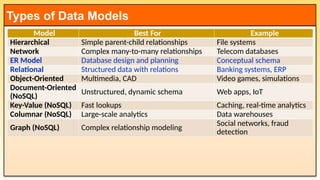
Types of DataModels
Model Best For Example
Hierarchical Simple parent-child relationships File systems
Network Complex many-to-many relationships Telecom databases
ER Model Database design and planning Conceptual schema
Relational Structured data with relations Banking systems, ERP
Object-Oriented Multimedia, CAD Video games, simulations
Document-Oriented
(NoSQL)
Unstructured, dynamic schema Web apps, IoT
Key-Value (NoSQL) Fast lookups Caching, real-time analytics
Columnar (NoSQL) Large-scale analytics Data warehouses
Graph (NoSQL) Complex relationship modeling
Social networks, fraud
detection
5.
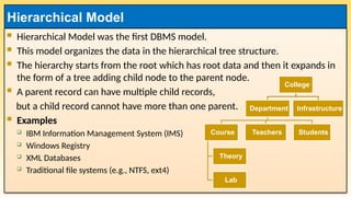
Hierarchical Modelwas the first DBMS model.
This model organizes the data in the hierarchical tree structure.
The hierarchy starts from the root which has root data and then it expands in
the form of a tree adding child node to the parent node.
A parent record can have multiple child records,
but a child record cannot have more than one parent.
Examples
IBM Information Management System (IMS)
Windows Registry
XML Databases
Traditional file systems (e.g., NTFS, ext4)
Hierarchical Model
College
Department
Course
Theory
Lab
Teachers Students
Infrastructure
6.
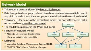
This modelis an extension of the hierarchical model.
Data is organized as a graph, where records (nodes) can have multiple parent
and child records. It was the most popular model before the relational model.
This model is the same as the hierarchical model, the only difference is that a
record can have more than one parent.
The model was popular in the 1960s and 1970s
Features of Network Model
Ability to Merge more Relationships,
Many paths & Circular Linked List
Examples
Integrated Database Management System (IDMS)
CODASYL DBMS, Raima Database Manager.
Network Model
7.
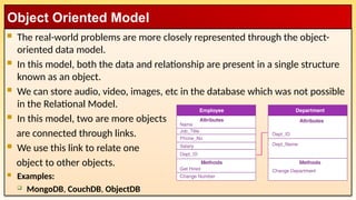
The real-worldproblems are more closely represented through the object-
oriented data model.
In this model, both the data and relationship are present in a single structure
known as an object.
We can store audio, video, images, etc in the database which was not possible
in the Relational Model.
In this model, two are more objects
are connected through links.
We use this link to relate one
object to other objects.
Examples:
MongoDB, CouchDB, ObjectDB
Object Oriented Model
8.
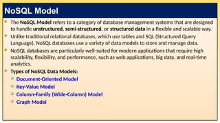
The NoSQLModel refers to a category of database management systems that are designed
to handle unstructured, semi-structured, or structured data in a flexible and scalable way.
Unlike traditional relational databases, which use tables and SQL (Structured Query
Language), NoSQL databases use a variety of data models to store and manage data.
NoSQL databases are particularly well-suited for modern applications that require high
scalability, flexibility, and performance, such as web applications, big data, and real-time
analytics.
Types of NoSQL Data Models:
Document-Oriented Model
Key-Value Model
Column-Family (Wide-Column) Model
Graph Model
NoSQL Model
9.
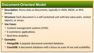
Description: Storesdata as documents, typically in JSON, BSON, or XML
format.
Structure: Each document is a self-contained unit with key-value pairs, nested
objects, or arrays.
Use Cases:
Content management systems (CMS).
E-commerce applications.
Real-time analytics.
Examples:
MongoDB: A popular document-oriented database.
CouchDB: A document database with a focus on ease of use and scalability.
Document-Oriented Model
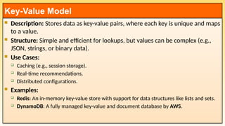
10.
Description: Storesdata as key-value pairs, where each key is unique and maps
to a value.
Structure: Simple and efficient for lookups, but values can be complex (e.g.,
JSON, strings, or binary data).
Use Cases:
Caching (e.g., session storage).
Real-time recommendations.
Distributed configurations.
Examples:
Redis: An in-memory key-value store with support for data structures like lists and sets.
DynamoDB: A fully managed key-value and document database by AWS.
Key-Value Model
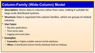
11.
Description: Storesdata in columns rather than rows, making it suitable for
large-scale distributed systems.
Structure: Data is organized into column families, which are groups of related
columns.
Use Cases:
Big data applications.
Time-series data.
Logging and event data.
Examples:
Cassandra: A highly scalable column-family database.
HBase: A distributed column-family database built on Hadoop.
Column-Family (Wide-Column) Model
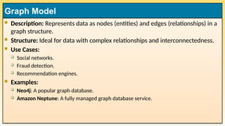
12.
Description: Representsdata as nodes (entities) and edges (relationships) in a
graph structure.
Structure: Ideal for data with complex relationships and interconnectedness.
Use Cases:
Social networks.
Fraud detection.
Recommendation engines.
Examples:
Neo4j: A popular graph database.
Amazon Neptune: A fully managed graph database service.
Graph Model
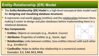
13.
The Entity-Relationship(ER) Model is a high-level conceptual data model used
for designing and visualizing database structures.
It represents real-world objects (entities) and the relationships between them,
making it easier to design and plan databases before implementing them in a
relational database.
Key Components:
Entities: Objects or concepts (e.g., Student, Course)
Attributes: Properties of entities (e.g., Name, Age)
Relationships: Links between entities, how entities interact with each other
(e.g., Enrolled in)
Cardinality: Helps to define the relationship in a numerical context.
Examples: 1:1, 1:M, M:1, M:N.
Entity-Relationship (ER) Model
14.
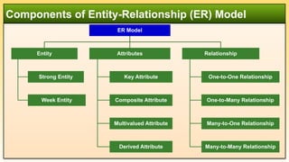
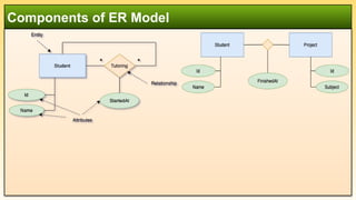
Components of Entity-Relationship(ER) Model
ER Model
Entity
Strong Entity
Week Entity
Attributes
Key Attribute
Composite Attribute
Multivalued Attribute
Derived Attribute
Relationship
One-to-One Relationship
One-to-Many Relationship
Many-to-One Relationship
Many-to-Many Relationship
15.
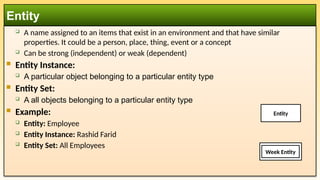
A nameassigned to an items that exist in an environment and that have similar
properties. It could be a person, place, thing, event or a concept
Can be strong (independent) or weak (dependent)
Entity Instance:
A particular object belonging to a particular entity type
Entity Set:
A all objects belonging to a particular entity type
Example:
Entity: Employee
Entity Instance: Rashid Farid
Entity Set: All Employees
Entity
Week Entity
Entity
16.
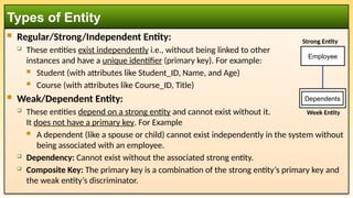
Regular/Strong/Independent Entity:
These entities exist independently i.e., without being linked to other
instances and have a unique identifier (primary key). For example:
Student (with attributes like Student_ID, Name, and Age)
Course (with attributes like Course_ID, Title)
Weak/Dependent Entity:
These entities depend on a strong entity and cannot exist without it.
It does not have a primary key. For Example
A dependent (like a spouse or child) cannot exist independently in the system without
being associated with an employee.
Dependency: Cannot exist without the associated strong entity.
Composite Key: The primary key is a combination of the strong entity’s primary key and
the weak entity’s discriminator.
Types of Entity
Dependents
Employee
Strong Entity
Week Entity
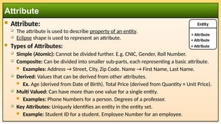
Attribute:
Theattribute is used to describe property of an entity.
Eclipse shape is used to represent an attribute.
Types of Attributes:
Simple (Atomic): Cannot be divided further. E.g. CNIC, Gender, Roll Number.
Composite: Can be divided into smaller sub-parts, each representing a basic attribute.
Examples: Address → Street, City, Zip Code. Name → First Name, Last Name.
Derived: Values that can be derived from other attributes.
Ex. Age (derived from Date of Birth). Total Price (derived from Quantity × Unit Price).
Multi Valued: Can have more than one value for a single entity.
Examples: Phone Numbers for a person. Degrees of a professor.
Key Attributes: Uniquely identifies an entity in the entity set.
Example: Student ID for a student. Employee Number for an employee.
Attribute
Entity
+ Attribute
+ Attribute
+ Attribute
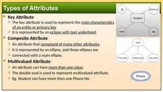
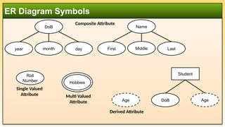
19.
Key Attribute
The key attribute is used to represent the main characteristics
of an entity or primary key
It is represented by an eclipse with text underlined.
Composite Attribute
An attribute that composed of many other attributes.
It is represented by an ellipse, and those ellipses are
connected with a main ellipse.
Multivalued Attribute
An attribute can have more than one value.
The double oval is used to represent multivalued attribute.
Eg. Student can have more then one Phone No.
Types of Attributes
Phone
20.
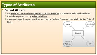
Derived Attribute
An attribute that can be derived from other attribute is known as a derived attribute.
It can be represented by a dashed ellipse.
A person's age changes over time and can be derived from another attribute like Date of
birth.
Types of Attributes
21.
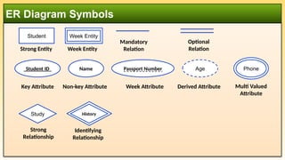
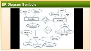
ER Diagram Symbols
StudentID
Key Attribute
Name
Non-key Attribute
Passport Number
Week Attribute
Age
Derived Attribute
Student
Strong Entity
Week Entity
Multi Valued
Attribute
Phone
Week Entity
Study
Strong
Relationship
Study
History
Identifying
Relationship
Mandatory
Relation
Optional
Relation
22.
ER Diagram Symbols
DoB
yearmonth day
Composite Attribute
Name
First Middle Last
Roll
Number
Single Valued
Attribute Multi Valued
Attribute
Hobbies
Age
Derived Attribute
Student
DoB Age
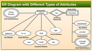
23.
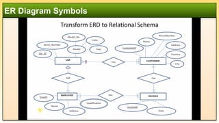
ER Diagram withDifferent Types of Attributes
mr no
Simple Attribute
patient id
Key Attribute
day
DoB
year month
Composite Attribute
Age
Derived Attribute
Multi Valued Attribute
Phone
Number
patient
Strong Entity
insurance id
Key Attribute
provider
Simple Attribute
Multi Valued Attribute
coverage
details
Insurance
Week Entity
Identifying
Relationship
Study
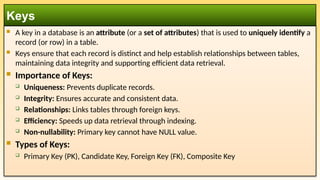
has
A keyin a database is an attribute (or a set of attributes) that is used to uniquely identify a
record (or row) in a table.
Keys ensure that each record is distinct and help establish relationships between tables,
maintaining data integrity and supporting efficient data retrieval.
Importance of Keys:
Uniqueness: Prevents duplicate records.
Integrity: Ensures accurate and consistent data.
Relationships: Links tables through foreign keys.
Efficiency: Speeds up data retrieval through indexing.
Non-nullability: Primary key cannot have NULL value.
Types of Keys:
Primary Key (PK), Candidate Key, Foreign Key (FK), Composite Key
Keys
26.
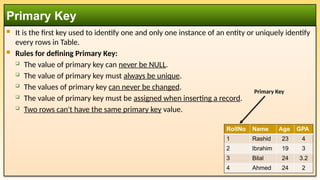
It isthe first key used to identify one and only one instance of an entity or uniquely identify
every rows in Table.
Rules for defining Primary Key:
The value of primary key can never be NULL.
The value of primary key must always be unique.
The values of primary key can never be changed.
The value of primary key must be assigned when inserting a record.
Two rows can't have the same primary key value.
Primary Key
RollNo Name Age GPA
1 Rashid 23 4
2 Ibrahim 19 3
3 Bilal 24 3.2
4 Ahmed 24 2
Primary Key
27.
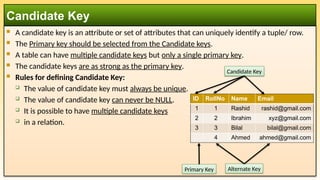
A candidatekey is an attribute or set of attributes that can uniquely identify a tuple/ row.
The Primary key should be selected from the Candidate keys.
A table can have multiple candidate keys but only a single primary key.
The candidate keys are as strong as the primary key.
Rules for defining Candidate Key:
The value of candidate key must always be unique.
The value of candidate key can never be NULL.
It is possible to have multiple candidate keys
in a relation.
Candidate Key
ID RollNo Name Email
1 1 Rashid rashid@gmail.com
2 2 Ibrahim xyz@gmail.com
3 3 Bilal bilal@gmail.com
4 Ahmed ahmed@gmail.com
Candidate Key
Alternate Key
Primary Key
28.
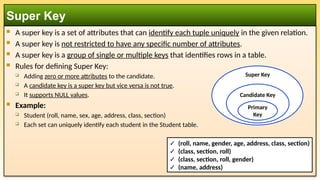
A superkey is a set of attributes that can identify each tuple uniquely in the given relation.
A super key is not restricted to have any specific number of attributes.
A super key is a group of single or multiple keys that identifies rows in a table.
Rules for defining Super Key:
Adding zero or more attributes to the candidate.
A candidate key is a super key but vice versa is not true.
It supports NULL values.
Example:
Student (roll, name, sex, age, address, class, section)
Each set can uniquely identify each student in the Student table.
Super Key
Candidate Key
Primary
Key
Super Key
✓ (roll, name, gender, age, address, class, section)
✓ (class, section, roll)
✓ (class, section, roll, gender)
✓ (name, address)
29.
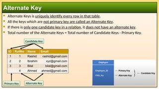
Alternate Keysis uniquely identify every row in that table.
All the keys which are not primary key are called an Alternate Key.
If there is only one candidate key in a relation, it does not have an alternate key.
Total number of the Alternate Keys = Total number of Candidate Keys - Primary Key.
Alternate Key
ID RollNo Name Email
1 1 Rashid rashid@gmail.com
2 2 Ibrahim xyz@gmail.com
3 3 Bilal bilal@gmail.com
4 Ahmed ahmed@gmail.com
Primary Key Alternate Key
Candidate Key
30.
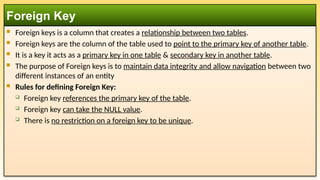
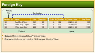
Foreign keysis a column that creates a relationship between two tables.
Foreign keys are the column of the table used to point to the primary key of another table.
It is a key it acts as a primary key in one table & secondary key in another table.
The purpose of Foreign keys is to maintain data integrity and allow navigation between two
different instances of an entity
Rules for defining Foreign Key:
Foreign key references the primary key of the table.
Foreign key can take the NULL value.
There is no restriction on a foreign key to be unique.
Foreign Key
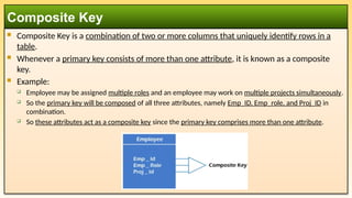
Composite Keyis a combination of two or more columns that uniquely identify rows in a
table.
Whenever a primary key consists of more than one attribute, it is known as a composite
key.
Example:
Employee may be assigned multiple roles and an employee may work on multiple projects simultaneously.
So the primary key will be composed of all three attributes, namely Emp_ID, Emp_role, and Proj_ID in
combination.
So these attributes act as a composite key since the primary key comprises more than one attribute.
Composite Key
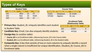
Primary Key:Student_ID, Uniquely identifies each student
in Student Table.
Candidate Key: Email, Can also uniquely identify students.
Foreign Key (in another table):
Course_ID in an Enrollment table, referencing Course_ID in the Course table.
Student_ID in an Enrollment table, referencing Student_ID in the Student table.
Composite Key: A key that consists of two or more columns to uniquely identify a record
when a single column is insufficient for unique identification. (Student_ID, Course_ID) in
Enrolment table.
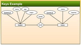
Types of Keys
Student_ID Name Age Major
101 Alice 22 CS
102 Bob 24 Math
103 John 23 CS
Course_ID Course_Name Instructor
CS101 Databases Dr. Smith
MT202 Algebra Dr. Lee
Student Table Course Table
Student_ID Course_ID Grade
101 CS101 A
102 MT202 B+
Enrollment Table
(Relationship Table)
35.
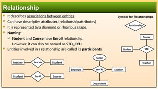
It describesassociations between entities.
Can have descriptive attributes (relationship attributes)
It is represented by a diamond or rhombus shape.
Naming:
Student and Course have Enroll relationship,
However, it can also be named as STD_COU
Entities involved in a relationship are called its participants
Relationship
Symbol for Relationships
Enroll Course
Student
Relationship
Course
Teacher
Student STC
Employee
Department
Location
works
Since
teaches Student
teacher
36.
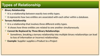
Binary Relationship
It is a relationship between exactly two entity types.
It represents how two entities are associated with each other within a database.
Ternary Relationship
It is a relationship that involves three different entity types.
It shows how three entities are related to one another simultaneously.
Cannot Be Replaced by Three Binary Relationships
Sometimes, breaking a ternary relationship into multiple binary relationships can lead
to loss of information or incorrect relationships.
Example: Supplier supplies a Product to a Project
Types of Relationship
37.
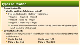
Ternary Relationship
Why Not Use Binary Relationships Instead?
If we tried to break this into binary relationships:
Supplier — (Supplies) — Product
Product — (Used in) — Project
Supplier — (Works for) — Project
This loses important information! It doesn't clearly specify which supplier supplied
which product to which project.
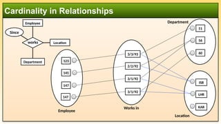
Cardinality Constraints
Specifies how many instances of one entity can be associated with instances of the other
entity these are
One-to-One (1:1) One-to-Many (1:M)
Many-to-One (M:1) Many-to-Many (1:1)
Types of Relation
38.
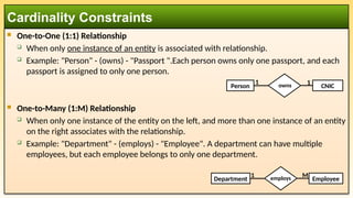
One-to-One (1:1)Relationship
When only one instance of an entity is associated with relationship.
Example: "Person" - (owns) - "Passport ".Each person owns only one passport, and each
passport is assigned to only one person.
One-to-Many (1:M) Relationship
When only one instance of the entity on the left, and more than one instance of an entity
on the right associates with the relationship.
Example: "Department" - (employs) - "Employee". A department can have multiple
employees, but each employee belongs to only one department.
Cardinality Constraints
employs Employee
Department
M
1
owns CNIC
Person
1 1
39.
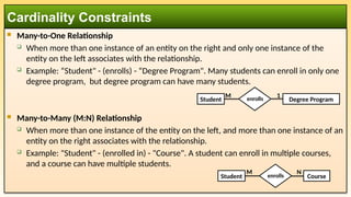
Many-to-One Relationship
When more than one instance of an entity on the right and only one instance of the
entity on the left associates with the relationship.
Example: “Student" - (enrolls) - “Degree Program". Many students can enroll in only one
degree program, but degree program can have many students.
Many-to-Many (M:N) Relationship
When more than one instance of the entity on the left, and more than one instance of an
entity on the right associates with the relationship.
Example: "Student" - (enrolled in) - "Course". A student can enroll in multiple courses,
and a course can have multiple students.
Cardinality Constraints
enrolls Course
Student
M N
enrolls Degree Program
Student
M 1
40.
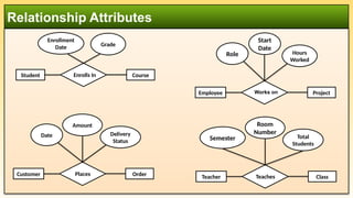
Relationship Attributes
Student EnrollsIn Course
Enrollment
Date Grade
Employee Works on Project
Hours
Worked
Role
Start
Date
Customer Places Order
Delivery
Status
Date
Amount
Teacher Teaches Class
Total
Students
Semester
Room
Number
41.
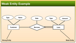
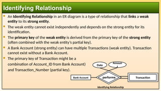
An IdentifyingRelationship in an ER diagram is a type of relationship that links a weak
entity to its strong entity.
The weak entity cannot exist independently and depends on the strong entity for its
identification.
The primary key of the weak entity is derived from the primary key of the strong entity
(often combined with the weak entity’s partial key).
A Bank Account (strong entity) can have multiple Transactions (weak entity). Transaction
cannot exist without a Bank Account.
The primary key of Transaction might be a
combination of Account_ID from Bank Account)
and Transaction_Number (partial key).
Identifying Relationship
Bank Account
Perform
transaction
Identifying Relationship
Date
Amoun
t
Study Transaction
performs
42.
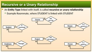
An EntityType linked with itself, is called recursive or unary relationship
Example Roommate, where STUDENT is linked with STUDENT
Recursive or a Unary Relationship
Student
Is
roommate
Course
has
pre-req
Person
is a
parent of
Person
is a
friend of
Employee Manages
Project
has
sub project
1
M
M
1
1
M
1
M
M
N
1
M
43.
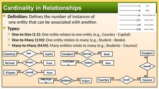
Definition: Definesthe number of instances of
one entity that can be associated with another.
Types:
One-to-One (1:1): One entity relates to one entity (e.g., Country - Capital)
One-to-Many (1:M): One entity relates to many (e.g., Student - Books)
Many-to-Many (M:M): Many entities relate to many (e.g., Students - Courses)
Cardinality in Relationships
Country Capital
1 has 1
Driver Truck
1 drives 1
Student Book
M borrow M
Custome
r
Item
M orders M
Player Team
M enroll 1
Employe
e
Project
M assigned M
Student
M
enroll
Course
M
Teacher teach
M M
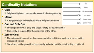
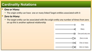
One:
Originentity has a one association with the target entity.
Many:
A Target entity can be related to the origin many times
One and Only One:
The origin entity has only one target entity associated with it
One entity is required for the existence of the other.
Zero to One:
The origin entity can either have no associated entities or up to one target entity
associated with it.
Notations that begin with zero generally indicate that the relationship is optional
Cardinality Notations
46.
One orMany:
The origin entity can have one or many linked Target entities associated with it
Zero to Many:
The target entity can be associated with the origin entity any number of times from zero
on up this is another optional relationship
Cardinality Notations
47.
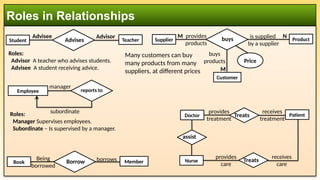
Roles in Relationships
Employeesupervises
manager
subordinate
reports to
Student supervises
Advisee
Advises Teacher
Advisor
Roles:
Manager Supervises employees.
Subordinate – Is supervised by a manager.
Roles:
Advisor A teacher who advises students.
Advisee A student receiving advice.
Treats
provides
treatment
receives
treatment
Book supervises
Borrow Member
Being
borrowed
borrows provides
care
receives
care
Patient
Many customers can buy
many products from many
suppliers, at different prices
Supplier supervises
buys
provides
products
is supplied
by a supplier
Customer
buys
products
Product
Price
M
M
N
assist
Doctor
Nurse Treats
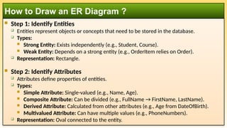
Step 1:Identify Entities
Entities represent objects or concepts that need to be stored in the database.
Types:
Strong Entity: Exists independently (e.g., Student, Course).
Weak Entity: Depends on a strong entity (e.g., OrderItem relies on Order).
Representation: Rectangle.
Step 2: Identify Attributes
Attributes define properties of entities.
Types:
Simple Attribute: Single-valued (e.g., Name, Age).
Composite Attribute: Can be divided (e.g., FullName → FirstName, LastName).
Derived Attribute: Calculated from other attributes (e.g., Age from DateOfBirth).
Multivalued Attribute: Can have multiple values (e.g., PhoneNumbers).
Representation: Oval connected to the entity.
How to Draw an ER Diagram ?
50.
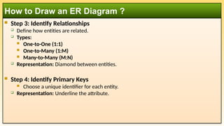
Step 3:Identify Relationships
Define how entities are related.
Types:
One-to-One (1:1)
One-to-Many (1:M)
Many-to-Many (M:N)
Representation: Diamond between entities.
Step 4: Identify Primary Keys
Choose a unique identifier for each entity.
Representation: Underline the attribute.
How to Draw an ER Diagram ?
51.
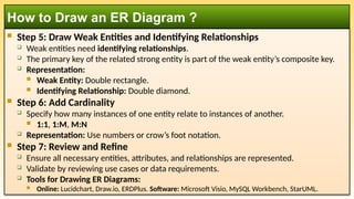
Step 5:Draw Weak Entities and Identifying Relationships
Weak entities need identifying relationships.
The primary key of the related strong entity is part of the weak entity’s composite key.
Representation:
Weak Entity: Double rectangle.
Identifying Relationship: Double diamond.
Step 6: Add Cardinality
Specify how many instances of one entity relate to instances of another.
1:1, 1:M, M:N
Representation: Use numbers or crow’s foot notation.
Step 7: Review and Refine
Ensure all necessary entities, attributes, and relationships are represented.
Validate by reviewing use cases or data requirements.
Tools for Drawing ER Diagrams:
Online: Lucidchart, Draw.io, ERDPlus. Software: Microsoft Visio, MySQL Workbench, StarUML.
How to Draw an ER Diagram ?