Download to read offline


![Network = 2n [n = number of ON bits (1’s)]
Host = 2h [h = number of OFF bits (0’s)]
Valid Host = Host – 2 *
* First IP(Host) of Network is use for network address
* Last IP(Host) of network is use for Broadcast address
192.168.1.0
255.255.255.0
11111111.11111111.11111111. 00000000
IP Address
Subnet Mask
Binary format
Network Bits Host Bits](https://image.slidesharecdn.com/networklayeronwardalllayers-240509074803-f1b2623b/75/Data-Communication-and-Network-Network-Layer-onward-all-layers-63-2048.jpg)


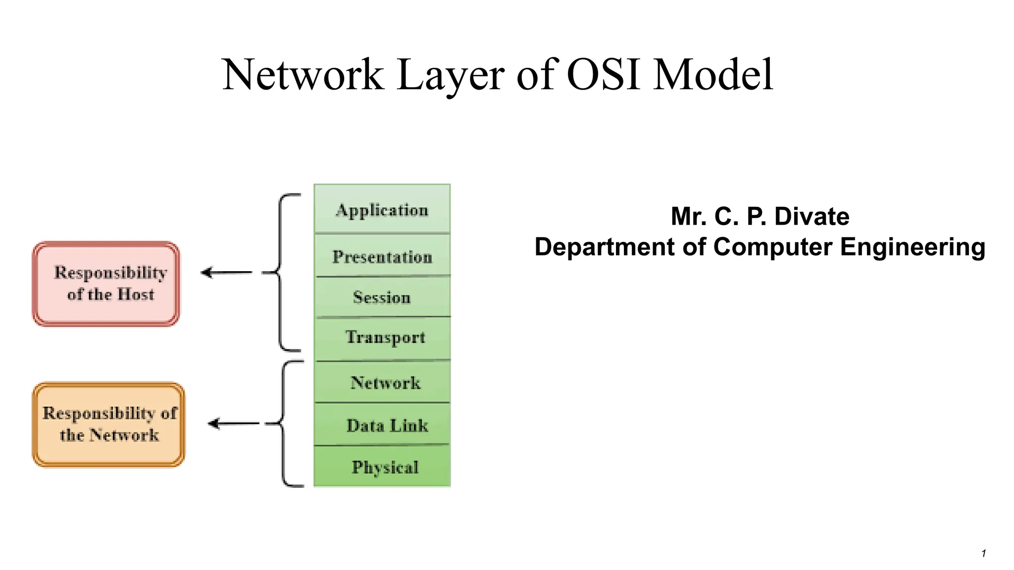
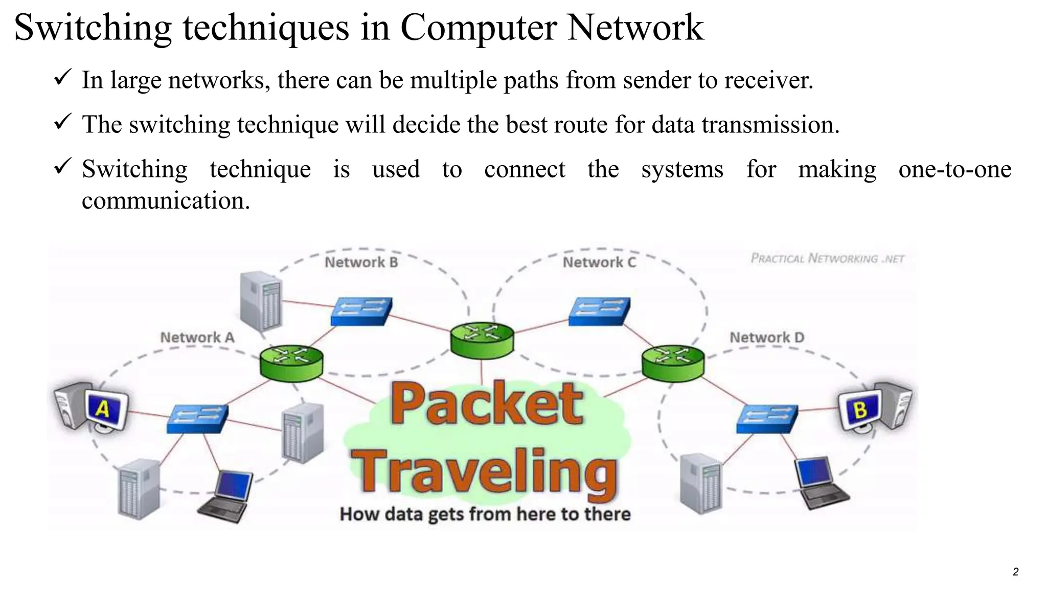
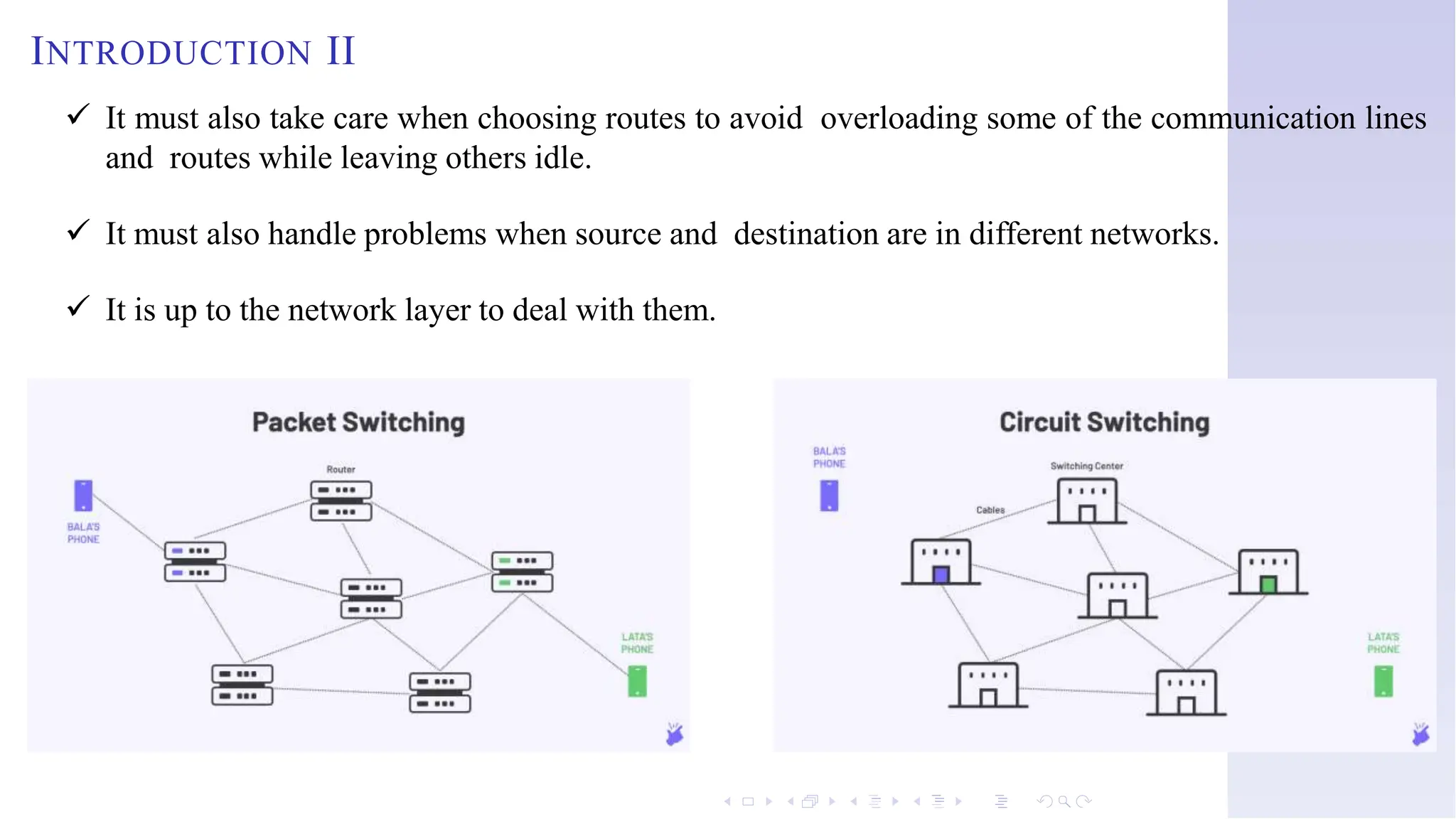
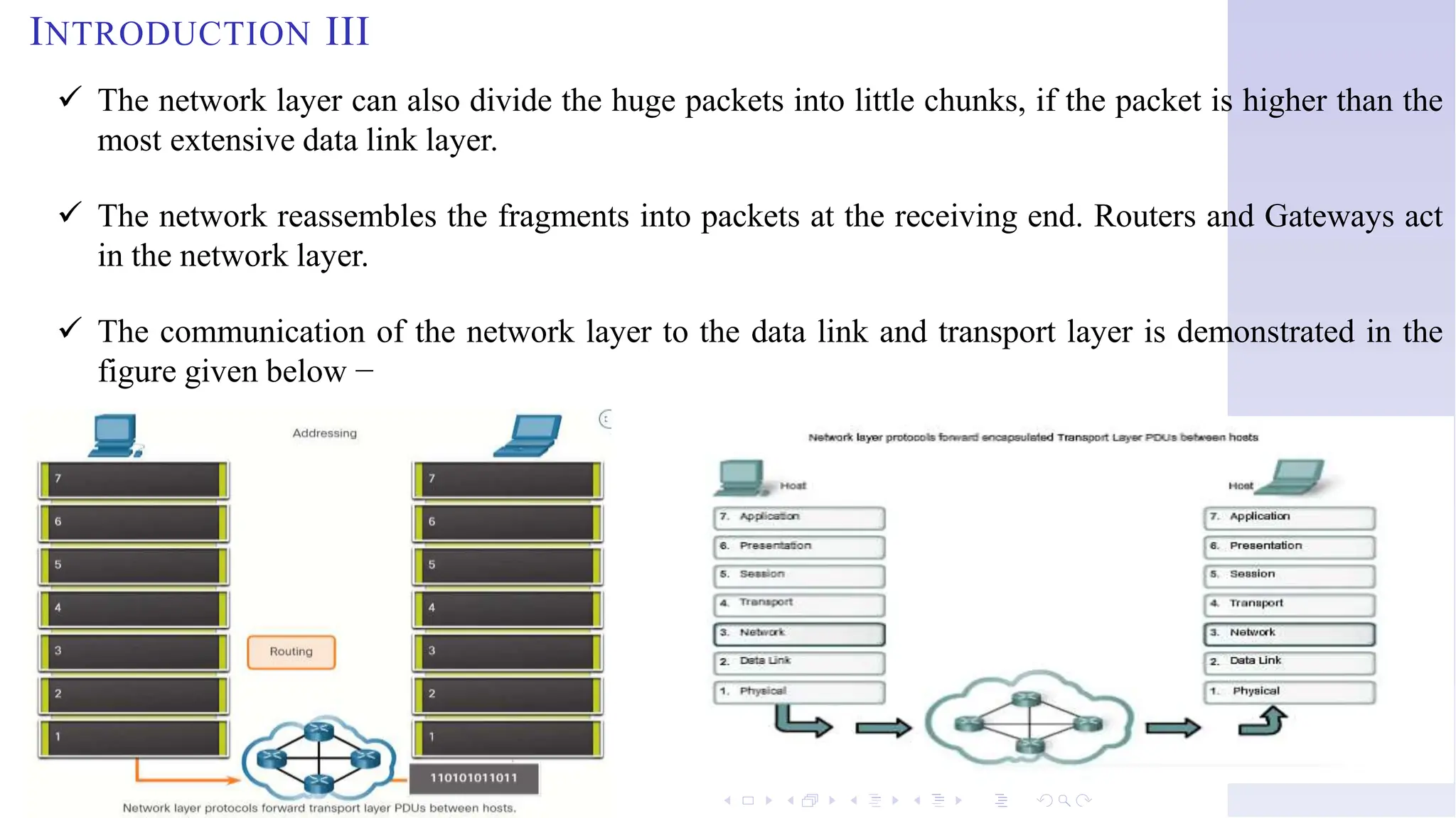
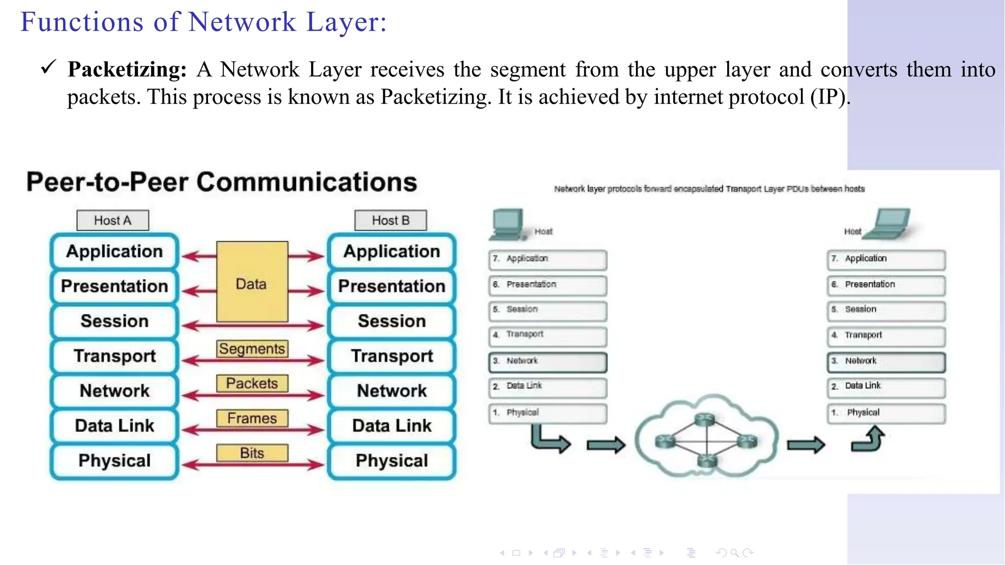
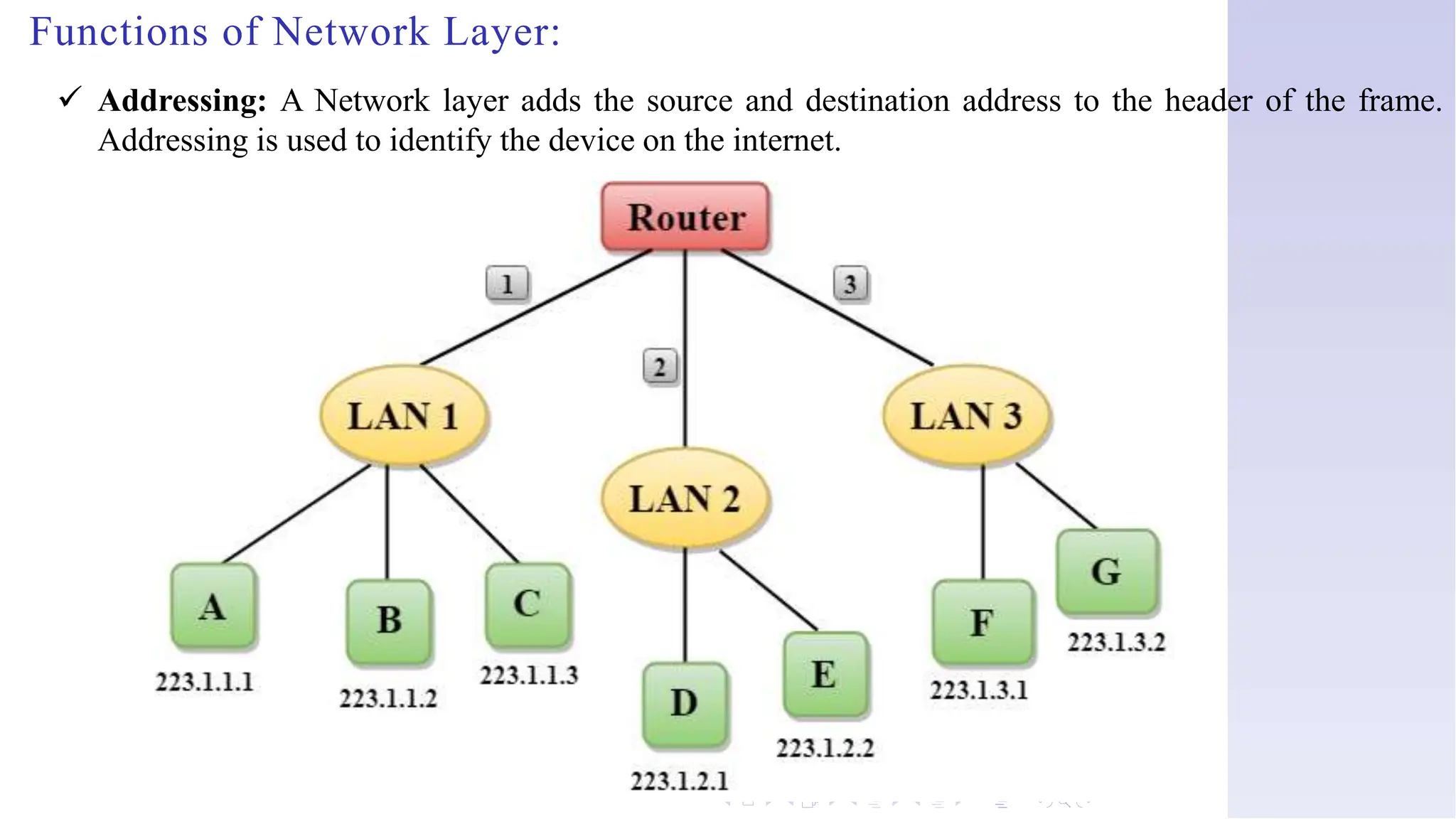
The document discusses switching techniques in computer networks, particularly focusing on circuit switching, message switching, and packet switching. It highlights the characteristics, advantages, and disadvantages of these techniques and explains multiplexing and its various forms. Additionally, it covers the network layer of the OSI model, emphasizing its functions such as internetworking, packetizing, and addressing.