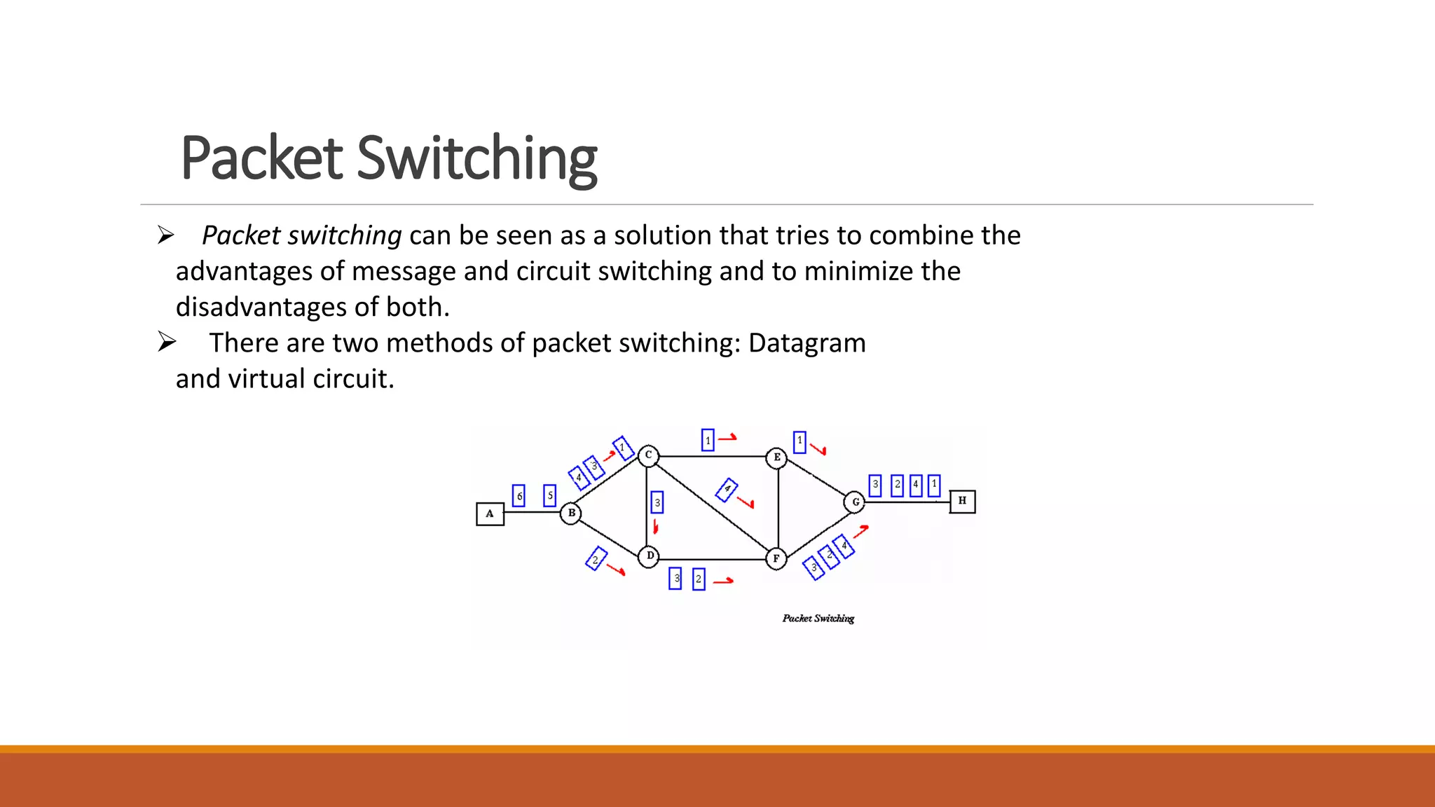
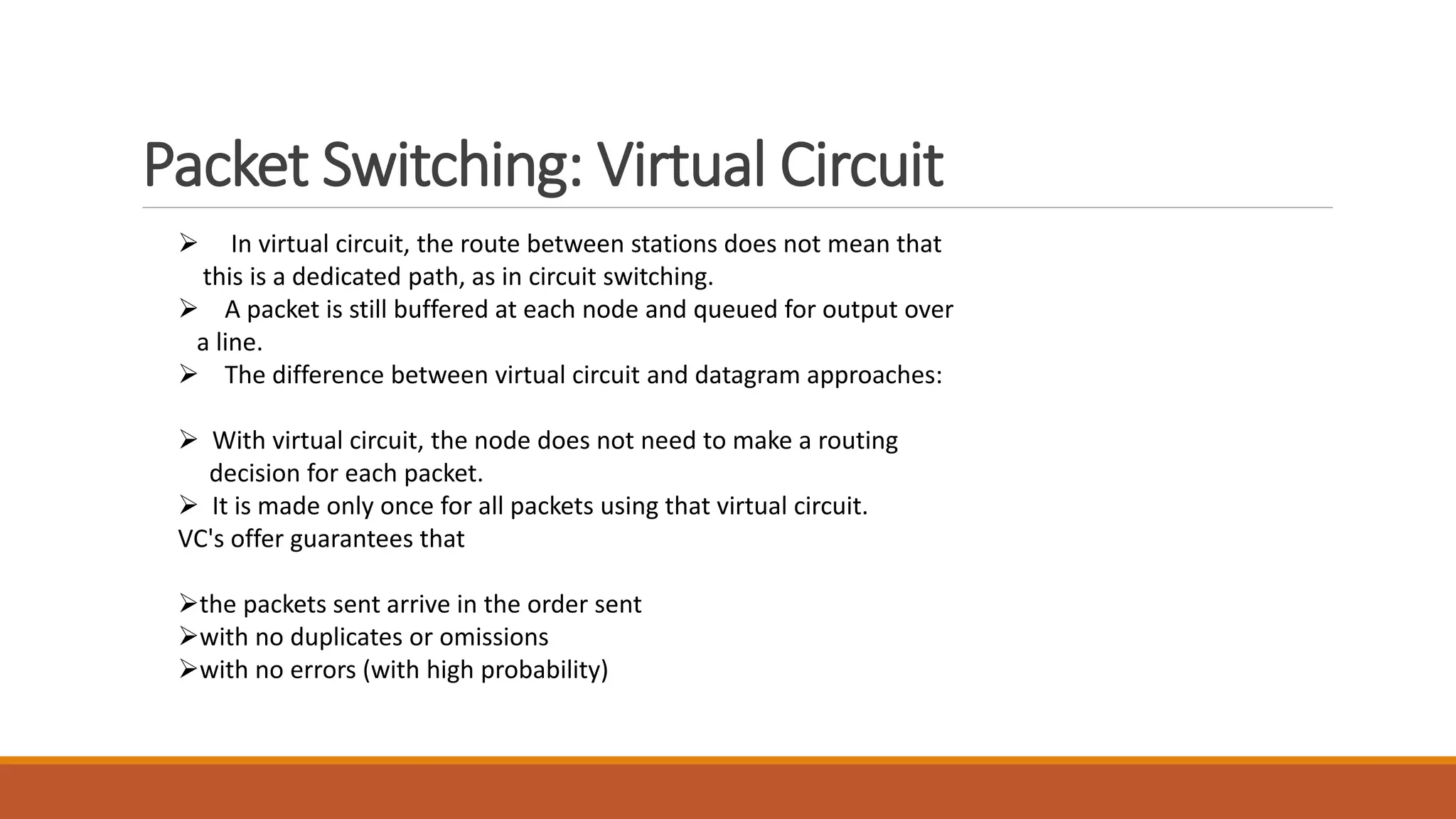
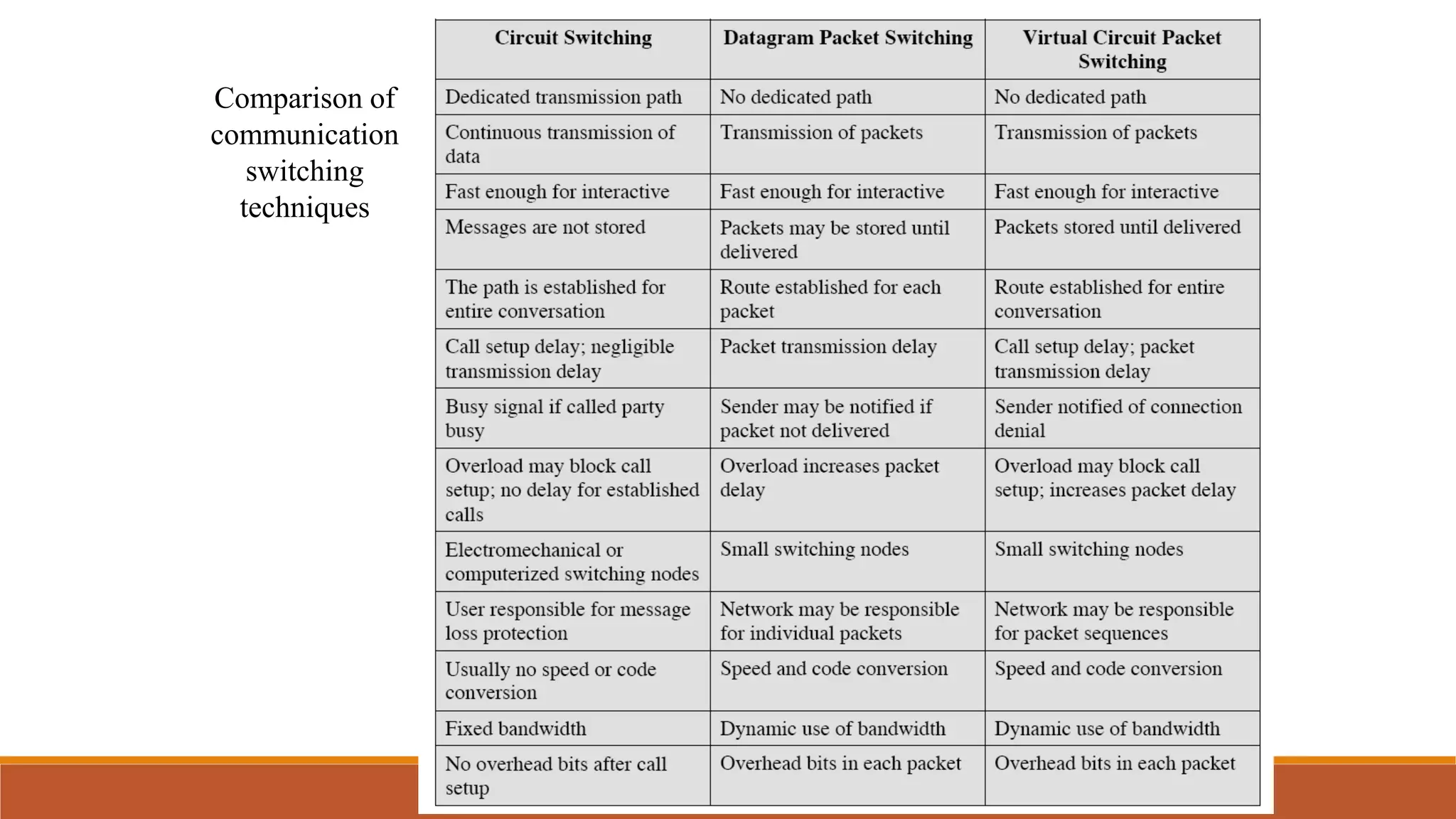
Switching Techniques
In large networks there might be multiple paths linking sender and receiver.
Information may be switched as it travels through various communication
channels. There are three typical switching techniques available for digital
traffic.
 Circuit Switching
 Message Switching
 Packet Switching
Circuit Switching
Circuit switching is a technique that directly connects the sender
and the receiver in an unbroken path.
◦ There is a dedicated communication path between two stations (end-to-
end)
◦ The path is a connected sequence of links between network nodes. On
each physical link, a logical channel is dedicated to the connection.
Communication via circuit switching has three phases:
◦ Circuit establishment (link by link)
◦ Routing & resource allocation
◦ Data transfer
◦ Circuit disconnect
◦ DE allocate the dedicated resources
The switches must know how to find the route to the destination
and how to allocate bandwidth (channel) to establish a connection.
Circuit Switching Properties
Inefficiency
◦ Channel capacity is dedicated for the whole duration of a connection
◦ If no data, capacity is wasted
Delay
◦ Long initial delay: circuit establishment takes time
◦ Low data delay: after the circuit establishment, information is transmitted at a fixed data rate
with no delay other than the propagation delay. The delay at each node is negligible.
Developed for voice traffic (public telephone network) but can also applied to
data traffic.
◦ For voice connections, the resulting circuit will enjoy a high percentage of utilization because
most of the time one party or the other is talking.
3
Message Switching
With message switching there is no need to establish a
dedicated path between two stations.
Each massage treat as independent unit with source and
destination address.
The message is then transmitted through the network, in its
entirety, from node to node.
Each node receives the entire message, stores it in its entirety
on disk, and then transmits the message to the next node.
This type of network is called a store-and-forward network.
Some delay occurs and require large capacity.
Packet Switching
 Packet switching can be seen as a solution that tries to combine the
advantages of message and circuit switching and to minimize the
disadvantages of both.
 There are two methods of packet switching: Datagram
and virtual circuit.
Packet Switching
 In both packet switching methods, a message is broken into
small parts, called packets.
 Each packet is tagged with appropriate source and destination
addresses.
 Since packets have a strictly defined maximum length, they
can be stored in main memory instead of disk, therefore access
delay and cost are minimized.
 Also the transmission speeds, between nodes, are optimized.
 With current technology, packets are generally accepted onto
the network on a first-come, first-served basis. If the network
becomes overloaded, packets are delayed or discarded.
Packet Switching: Datagram
 Datagram packet switching is similar to message switching in
that each packet is a self-contained unit with complete
addressing information attached.
 This fact allows packets to take a variety of possible paths
through the network.
 So the packets, each with the same destination address, do not
follow the same route, and they may arrive out of sequence at
the exit point node (or the destination).
 Reordering is done at the destination point based on the
sequence number of the packets.
 It is possible for a packet to be destroyed if one of the nodes on
its way is crashed momentarily. Thus all its queued packets may
be lost.
Packet Switching: Virtual Circuit
 In the virtual circuit approach, a preplanned route is established
before any data packets are sent.
A logical connection is established when
 a sender send a "call request packet" to the receiver and
the receiver send back an acknowledge packet "call accepted
packet" to the sender if the receiver agrees on conversational
parameters.
 The conversational parameters can be maximum packet sizes,
path to be taken, and other variables necessary to establish and
maintain the conversation.
 Virtual circuits imply acknowledgements, flow control, and error
control, so virtual circuits are reliable.
 That is, they have the capability to inform upper-protocol layers
if a transmission problem occurs.
Packet Switching: Virtual Circuit
 In virtual circuit, the route between stations does not mean that
this is a dedicated path, as in circuit switching.
 A packet is still buffered at each node and queued for output over
a line.
 The difference between virtual circuit and datagram approaches:
 With virtual circuit, the node does not need to make a routing
decision for each packet.
 It is made only once for all packets using that virtual circuit.
VC's offer guarantees that
the packets sent arrive in the order sent
with no duplicates or omissions
with no errors (with high probability)
Comparison of
communication
switching
techniques

switching techniques

  • 1.
    Switching Techniques In largenetworks there might be multiple paths linking sender and receiver. Information may be switched as it travels through various communication channels. There are three typical switching techniques available for digital traffic.  Circuit Switching  Message Switching  Packet Switching
  • 2.
    Circuit Switching Circuit switchingis a technique that directly connects the sender and the receiver in an unbroken path. ◦ There is a dedicated communication path between two stations (end-to- end) ◦ The path is a connected sequence of links between network nodes. On each physical link, a logical channel is dedicated to the connection. Communication via circuit switching has three phases: ◦ Circuit establishment (link by link) ◦ Routing & resource allocation ◦ Data transfer ◦ Circuit disconnect ◦ DE allocate the dedicated resources The switches must know how to find the route to the destination and how to allocate bandwidth (channel) to establish a connection.
  • 3.
    Circuit Switching Properties Inefficiency ◦Channel capacity is dedicated for the whole duration of a connection ◦ If no data, capacity is wasted Delay ◦ Long initial delay: circuit establishment takes time ◦ Low data delay: after the circuit establishment, information is transmitted at a fixed data rate with no delay other than the propagation delay. The delay at each node is negligible. Developed for voice traffic (public telephone network) but can also applied to data traffic. ◦ For voice connections, the resulting circuit will enjoy a high percentage of utilization because most of the time one party or the other is talking. 3
  • 4.
    Message Switching With messageswitching there is no need to establish a dedicated path between two stations. Each massage treat as independent unit with source and destination address. The message is then transmitted through the network, in its entirety, from node to node. Each node receives the entire message, stores it in its entirety on disk, and then transmits the message to the next node. This type of network is called a store-and-forward network. Some delay occurs and require large capacity.
  • 5.
    Packet Switching  Packetswitching can be seen as a solution that tries to combine the advantages of message and circuit switching and to minimize the disadvantages of both.  There are two methods of packet switching: Datagram and virtual circuit.
  • 6.
    Packet Switching  Inboth packet switching methods, a message is broken into small parts, called packets.  Each packet is tagged with appropriate source and destination addresses.  Since packets have a strictly defined maximum length, they can be stored in main memory instead of disk, therefore access delay and cost are minimized.  Also the transmission speeds, between nodes, are optimized.  With current technology, packets are generally accepted onto the network on a first-come, first-served basis. If the network becomes overloaded, packets are delayed or discarded.
  • 7.
    Packet Switching: Datagram Datagram packet switching is similar to message switching in that each packet is a self-contained unit with complete addressing information attached.  This fact allows packets to take a variety of possible paths through the network.  So the packets, each with the same destination address, do not follow the same route, and they may arrive out of sequence at the exit point node (or the destination).  Reordering is done at the destination point based on the sequence number of the packets.  It is possible for a packet to be destroyed if one of the nodes on its way is crashed momentarily. Thus all its queued packets may be lost.
  • 8.
    Packet Switching: VirtualCircuit  In the virtual circuit approach, a preplanned route is established before any data packets are sent. A logical connection is established when  a sender send a "call request packet" to the receiver and the receiver send back an acknowledge packet "call accepted packet" to the sender if the receiver agrees on conversational parameters.  The conversational parameters can be maximum packet sizes, path to be taken, and other variables necessary to establish and maintain the conversation.  Virtual circuits imply acknowledgements, flow control, and error control, so virtual circuits are reliable.  That is, they have the capability to inform upper-protocol layers if a transmission problem occurs.
  • 9.
    Packet Switching: VirtualCircuit  In virtual circuit, the route between stations does not mean that this is a dedicated path, as in circuit switching.  A packet is still buffered at each node and queued for output over a line.  The difference between virtual circuit and datagram approaches:  With virtual circuit, the node does not need to make a routing decision for each packet.  It is made only once for all packets using that virtual circuit. VC's offer guarantees that the packets sent arrive in the order sent with no duplicates or omissions with no errors (with high probability)
  • 10.