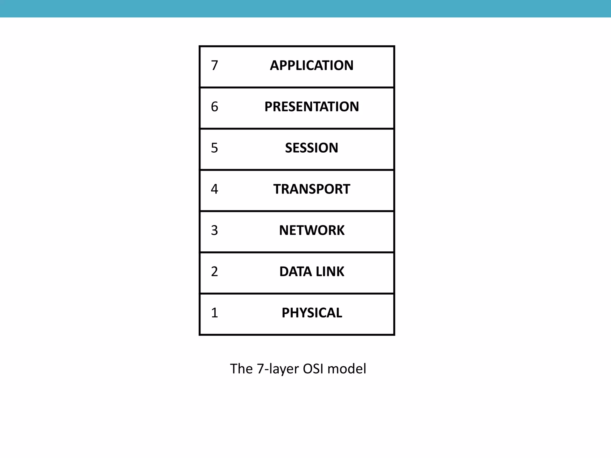
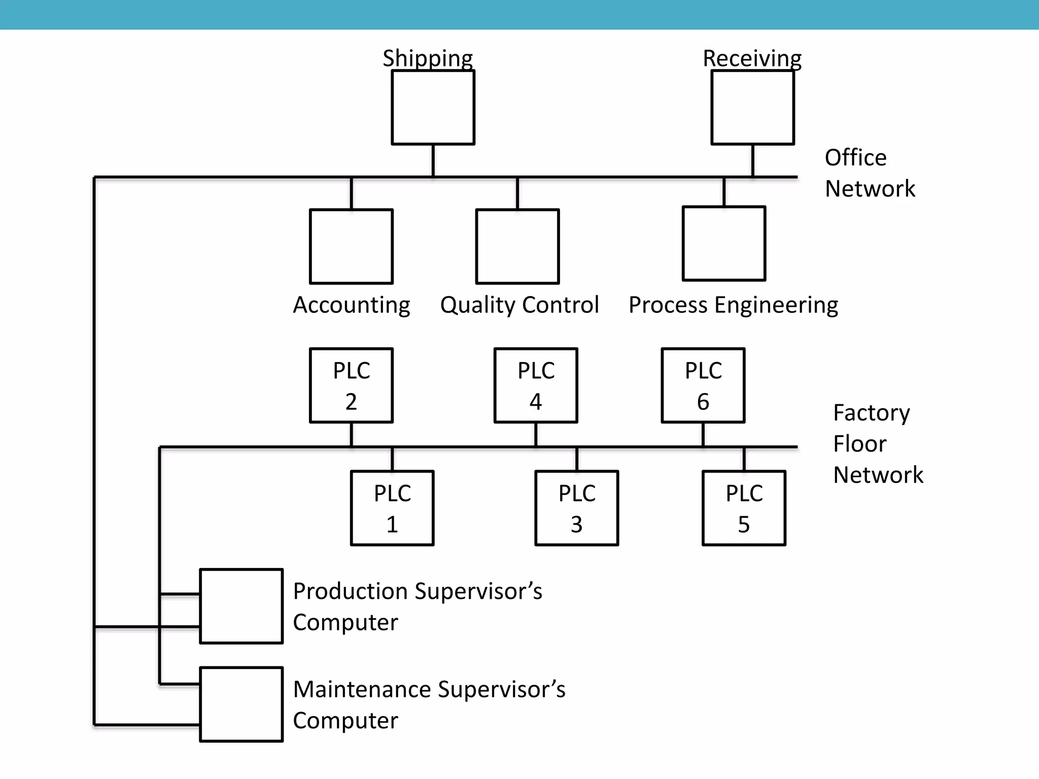
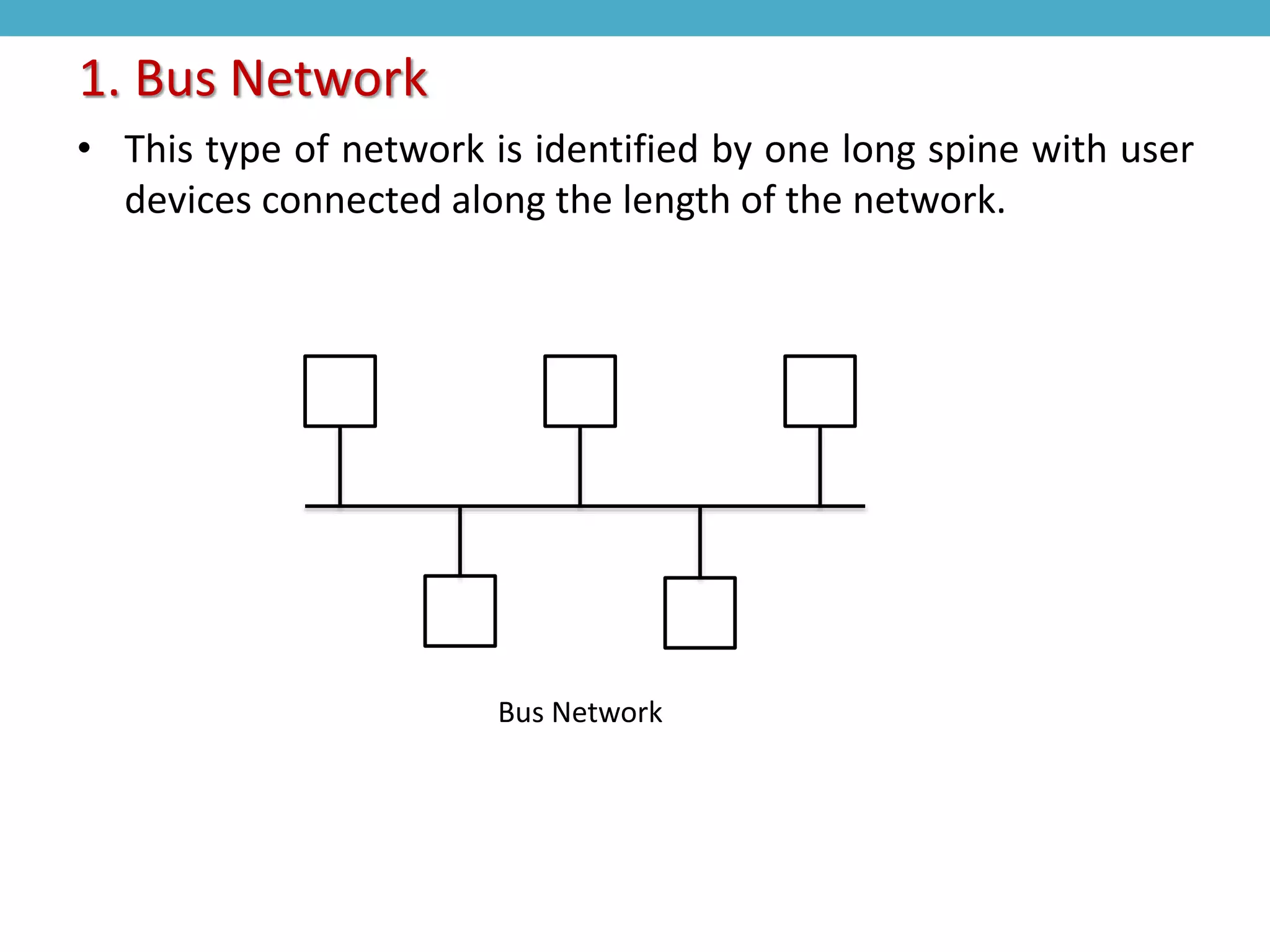
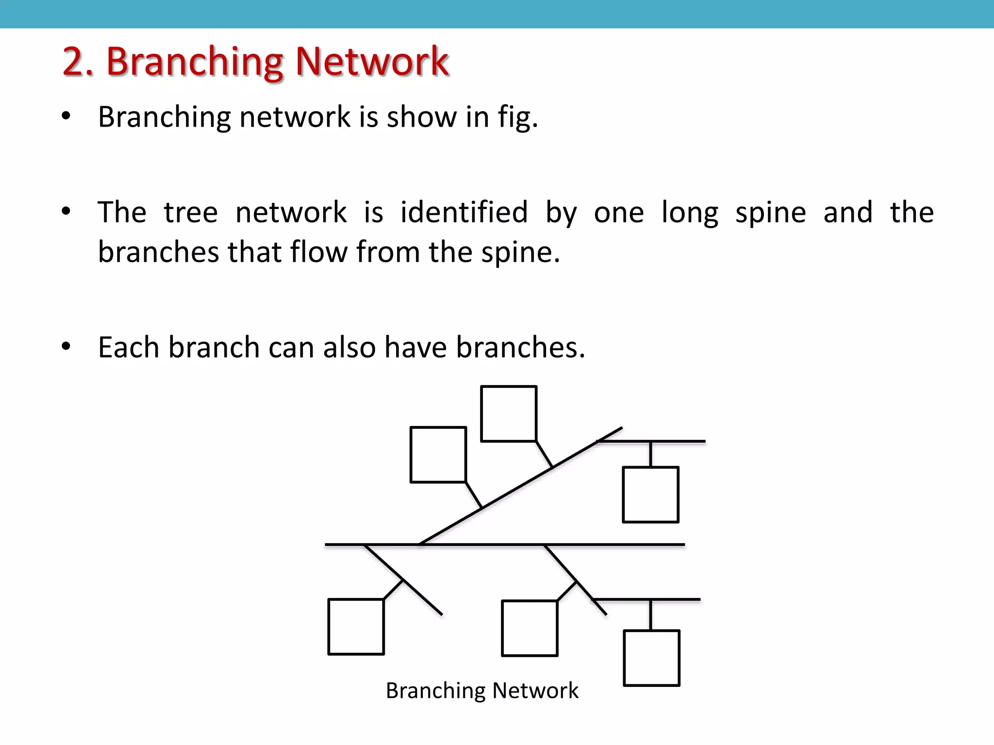
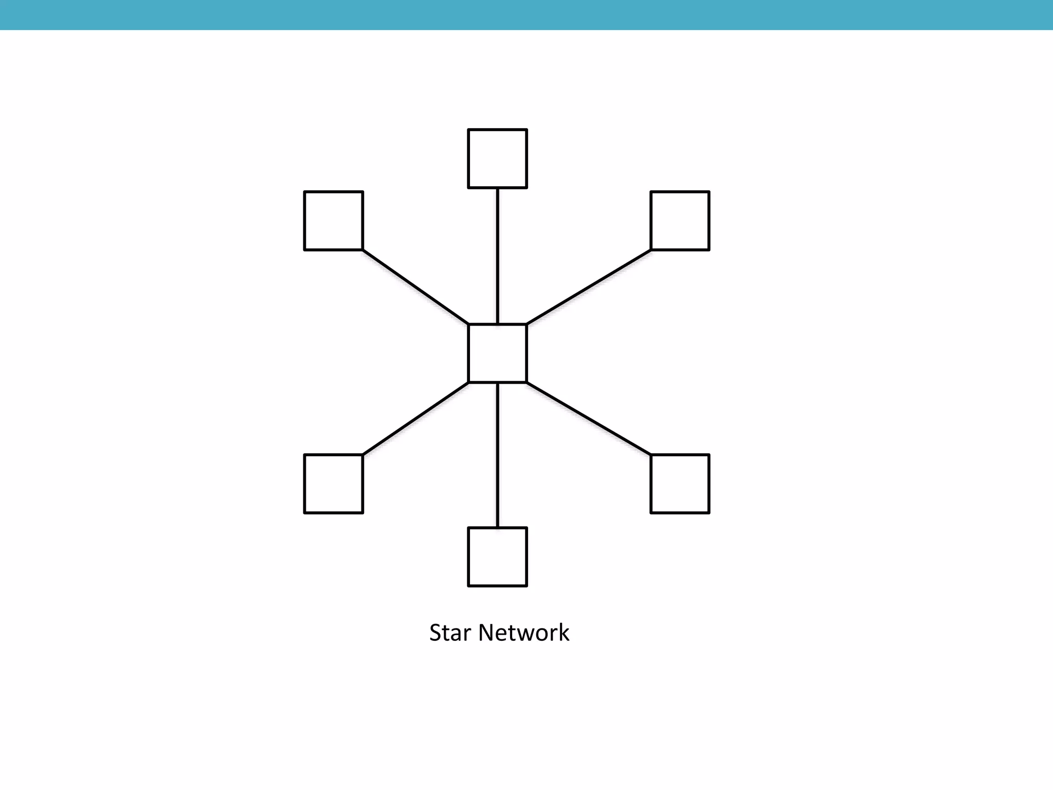
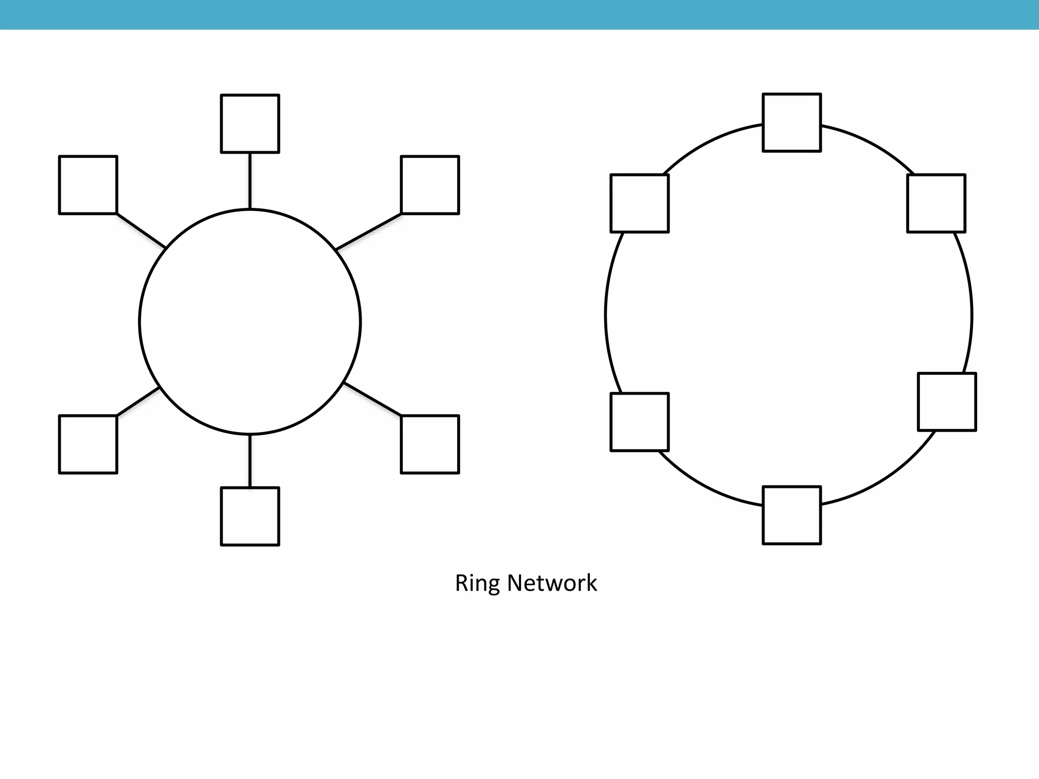
DATA COMMUNICATION
NETWORK
By :-
HARSHKUMAR MANILAL PATEL
Lukhdhirji Engineering College
1st ME Power System
Enrollment No.:-130310737010
 Network Architectures
• Application Layer
• Presentation Layer
• Session Layer
• Transport Layer
• Network Layer
• Data Link Layer
• Physical Layer
 Typical Network Topologies
• Bus Network
• Branching Network
• Star Network
• Ring Network
Content:-
Network Architectures
• All electronic data communications equipment today use one
or more layer of the 7-layer OSI model.
• Each application may use one or all of the layers.
• The lowest level sa the simplest lavels,and they will use in
almost every application.
• The upper 4 lavels are more complex and are only use in more
sophisticated systems.
• This that you may work with only the first three or four layers
most of time.
7 APPLICATION
6 PRESENTATION
5 SESSION
4 TRANSPORT
3 NETWORK
2 DATA LINK
1 PHYSICAL
The 7-layer OSI model
• This layer is the physical layer and it has the job of moving the
electrical signal from one point to another.
• This layer include the wire of cable through which data are
sent.
• This layer also includes the electrical on-off pulse that move
through the wire.
• This layer is only concerned with the physical medium of
transporting the signal from one point to another.
• This layer does not provide any error detection, error control,
or sequencing of data.
• This layer include wire specifications and cable termination
specifications.
1. The Physical Layer
• The data layer combines with the physical layer to make more
reliable system in that it add error detection and error
recovery methods.
• The rules for this layer are usually called protocols.
• This layer will include a means to start and stop the data flow,
away to package each part of the data.
• A means of sequencing when data are sent and when they are
received, a means to acknowledge that data have been
received.
• A means of providing timing that includes when the data are
being sent and how long to wait if data have not arrived.
2. The Data Link Layer
• The primary function of the network layer is to provide a
delivery mechanism for the transport layer.
• This use when the unit that is connected to the data
communications system is part of a multiple-unit network
rather than one single unit connected to only one other single
unit.
• The network layer use a combination of hardware and
software.
• Provide protocols like the x.21.x.25, and x.75.
• This also use when one network must interface with other
network.
3. The Network Layer
• The transport layer provides connections from one network to
another.
• Also provides a means of keeping the upper layers from
knowing what the lower layers are doing.
• This is the layer that begins to be different in various type of
network.
• With this possible to use a variety of different networks
because they are fundamentally similar in first three layer.
• In this layer and upper layers, the syatem tend to become very
complex and may have a variety of differences.
4. The Transport Layer
• The session layer establishes sessions between user,
maintains the sessions between users, terminates the
sessions between users.
• The major function of this layer also includes connections of
two separate open systems.ISO 8326 and CCITT.X212 are
standards for the session layer.
• When one unit on one network requests data from a unit on a
second network, the session layer directs the transport layer
to make proper connection.
• And regulate the flow of data smoothly interface the
connections and data flow between the two networks.
5. The Session Layer
• This layer transforms data information so that one network
can pass information to or receive information from another
network.
• The protocols for this layer are contained in ISO 8823 and
CCITT X.226.
• This layer works closely with the session layer to make the
connection between system works smoothiy.
• This layer is vital if you want to have the networks open to the
largest number of different users.
6. The Presentation Layer
PLC
2
PLC
1
PLC
4
PLC
3
PLC
6
PLC
5
Shipping Receiving
Office
Network
Factory
Floor
Network
Quality ControlAccounting Process Engineering
Production Supervisor’s
Computer
Maintenance Supervisor’s
Computer
• This layer provides the functions of making all of the other
layers compatible when users must interconnect between
multiple network.
• The protocols in the application layer provide this function.
7. The Application Layer
Typical Network Topologies
• Local area networks can be classified as baseband or
broadband networks.
• A baseband network is usually limited to equipment that is
connected over short distances.
• A broadband network depends on multiplexing techniques to
split the network into multiple channels.
• Four Types Of network Topologies that are commonly use in
industrial data communications systems.
1. Bus
2. Branching
3. Star
4. Ring
Types Of Network Topologies
• This type of network is identified by one long spine with user
devices connected along the length of the network.
1. Bus Network
Bus Network
• Branching network is show in fig.
• The tree network is identified by one long spine and the
branches that flow from the spine.
• Each branch can also have branches.
2. Branching Network
Branching Network
• The star network is identified by a central node on the
network with all other branches of the network emanating
from the center node.
• The computer at the end of each branch can fail without
harming data that are passed to other branches.
• If the computer that acts as the central node fails, the entaire
network will become disabled.
3. Star Network
Star Network
• The ring network is identified by a main spine that is closed in
the shape of a ring.
• In both variations, data information flows in only one
direction around the ring.
• The first variation of this type of network shows the main
network spine connected in a circle and each node is tap off
the main spine, much like the bus network.
• The second variation of the ring network shows each tap as an
integral part of the ring.
4. Ring Network
Ring Network
Thank You

Data comminication network

  • 1.
    DATA COMMUNICATION NETWORK By :- HARSHKUMARMANILAL PATEL Lukhdhirji Engineering College 1st ME Power System Enrollment No.:-130310737010
  • 2.
     Network Architectures •Application Layer • Presentation Layer • Session Layer • Transport Layer • Network Layer • Data Link Layer • Physical Layer  Typical Network Topologies • Bus Network • Branching Network • Star Network • Ring Network Content:-
  • 3.
    Network Architectures • Allelectronic data communications equipment today use one or more layer of the 7-layer OSI model. • Each application may use one or all of the layers. • The lowest level sa the simplest lavels,and they will use in almost every application. • The upper 4 lavels are more complex and are only use in more sophisticated systems. • This that you may work with only the first three or four layers most of time.
  • 4.
    7 APPLICATION 6 PRESENTATION 5SESSION 4 TRANSPORT 3 NETWORK 2 DATA LINK 1 PHYSICAL The 7-layer OSI model
  • 5.
    • This layeris the physical layer and it has the job of moving the electrical signal from one point to another. • This layer include the wire of cable through which data are sent. • This layer also includes the electrical on-off pulse that move through the wire. • This layer is only concerned with the physical medium of transporting the signal from one point to another. • This layer does not provide any error detection, error control, or sequencing of data. • This layer include wire specifications and cable termination specifications. 1. The Physical Layer
  • 6.
    • The datalayer combines with the physical layer to make more reliable system in that it add error detection and error recovery methods. • The rules for this layer are usually called protocols. • This layer will include a means to start and stop the data flow, away to package each part of the data. • A means of sequencing when data are sent and when they are received, a means to acknowledge that data have been received. • A means of providing timing that includes when the data are being sent and how long to wait if data have not arrived. 2. The Data Link Layer
  • 7.
    • The primaryfunction of the network layer is to provide a delivery mechanism for the transport layer. • This use when the unit that is connected to the data communications system is part of a multiple-unit network rather than one single unit connected to only one other single unit. • The network layer use a combination of hardware and software. • Provide protocols like the x.21.x.25, and x.75. • This also use when one network must interface with other network. 3. The Network Layer
  • 8.
    • The transportlayer provides connections from one network to another. • Also provides a means of keeping the upper layers from knowing what the lower layers are doing. • This is the layer that begins to be different in various type of network. • With this possible to use a variety of different networks because they are fundamentally similar in first three layer. • In this layer and upper layers, the syatem tend to become very complex and may have a variety of differences. 4. The Transport Layer
  • 9.
    • The sessionlayer establishes sessions between user, maintains the sessions between users, terminates the sessions between users. • The major function of this layer also includes connections of two separate open systems.ISO 8326 and CCITT.X212 are standards for the session layer. • When one unit on one network requests data from a unit on a second network, the session layer directs the transport layer to make proper connection. • And regulate the flow of data smoothly interface the connections and data flow between the two networks. 5. The Session Layer
  • 10.
    • This layertransforms data information so that one network can pass information to or receive information from another network. • The protocols for this layer are contained in ISO 8823 and CCITT X.226. • This layer works closely with the session layer to make the connection between system works smoothiy. • This layer is vital if you want to have the networks open to the largest number of different users. 6. The Presentation Layer
  • 11.
    PLC 2 PLC 1 PLC 4 PLC 3 PLC 6 PLC 5 Shipping Receiving Office Network Factory Floor Network Quality ControlAccountingProcess Engineering Production Supervisor’s Computer Maintenance Supervisor’s Computer
  • 12.
    • This layerprovides the functions of making all of the other layers compatible when users must interconnect between multiple network. • The protocols in the application layer provide this function. 7. The Application Layer
  • 13.
    Typical Network Topologies •Local area networks can be classified as baseband or broadband networks. • A baseband network is usually limited to equipment that is connected over short distances. • A broadband network depends on multiplexing techniques to split the network into multiple channels.
  • 14.
    • Four TypesOf network Topologies that are commonly use in industrial data communications systems. 1. Bus 2. Branching 3. Star 4. Ring Types Of Network Topologies
  • 15.
    • This typeof network is identified by one long spine with user devices connected along the length of the network. 1. Bus Network Bus Network
  • 16.
    • Branching networkis show in fig. • The tree network is identified by one long spine and the branches that flow from the spine. • Each branch can also have branches. 2. Branching Network Branching Network
  • 17.
    • The starnetwork is identified by a central node on the network with all other branches of the network emanating from the center node. • The computer at the end of each branch can fail without harming data that are passed to other branches. • If the computer that acts as the central node fails, the entaire network will become disabled. 3. Star Network
  • 18.
  • 19.
    • The ringnetwork is identified by a main spine that is closed in the shape of a ring. • In both variations, data information flows in only one direction around the ring. • The first variation of this type of network shows the main network spine connected in a circle and each node is tap off the main spine, much like the bus network. • The second variation of the ring network shows each tap as an integral part of the ring. 4. Ring Network
  • 20.
  • 21.