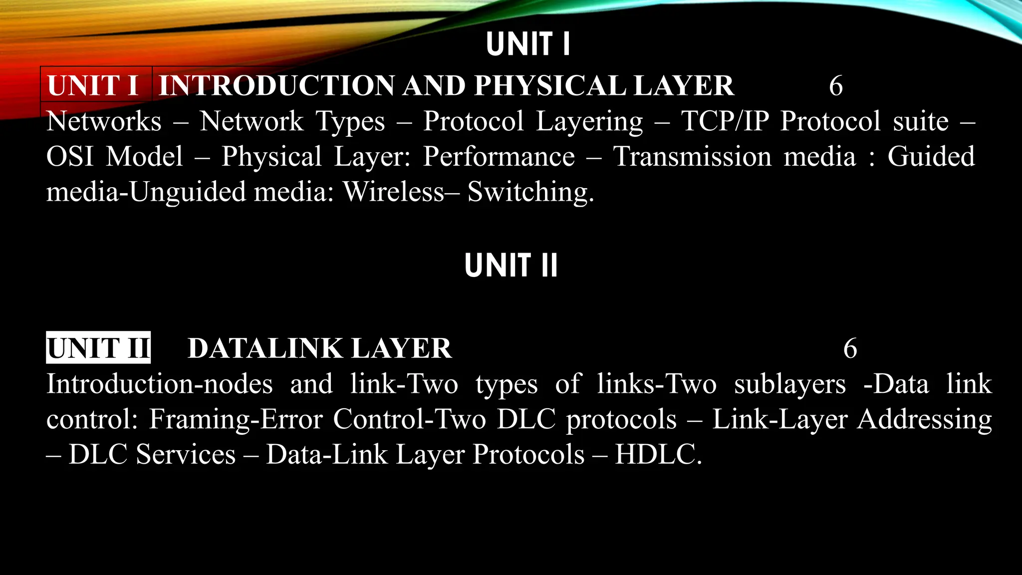
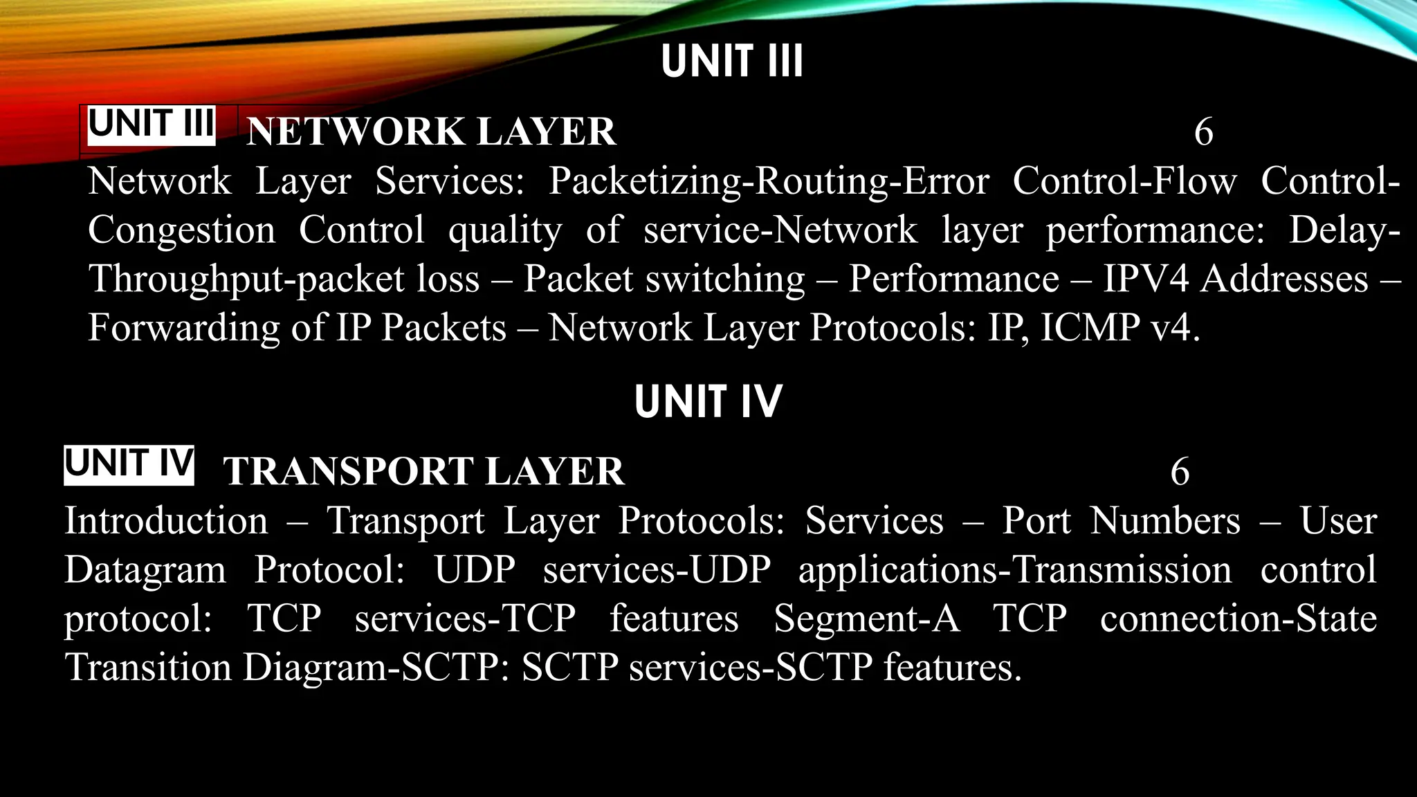
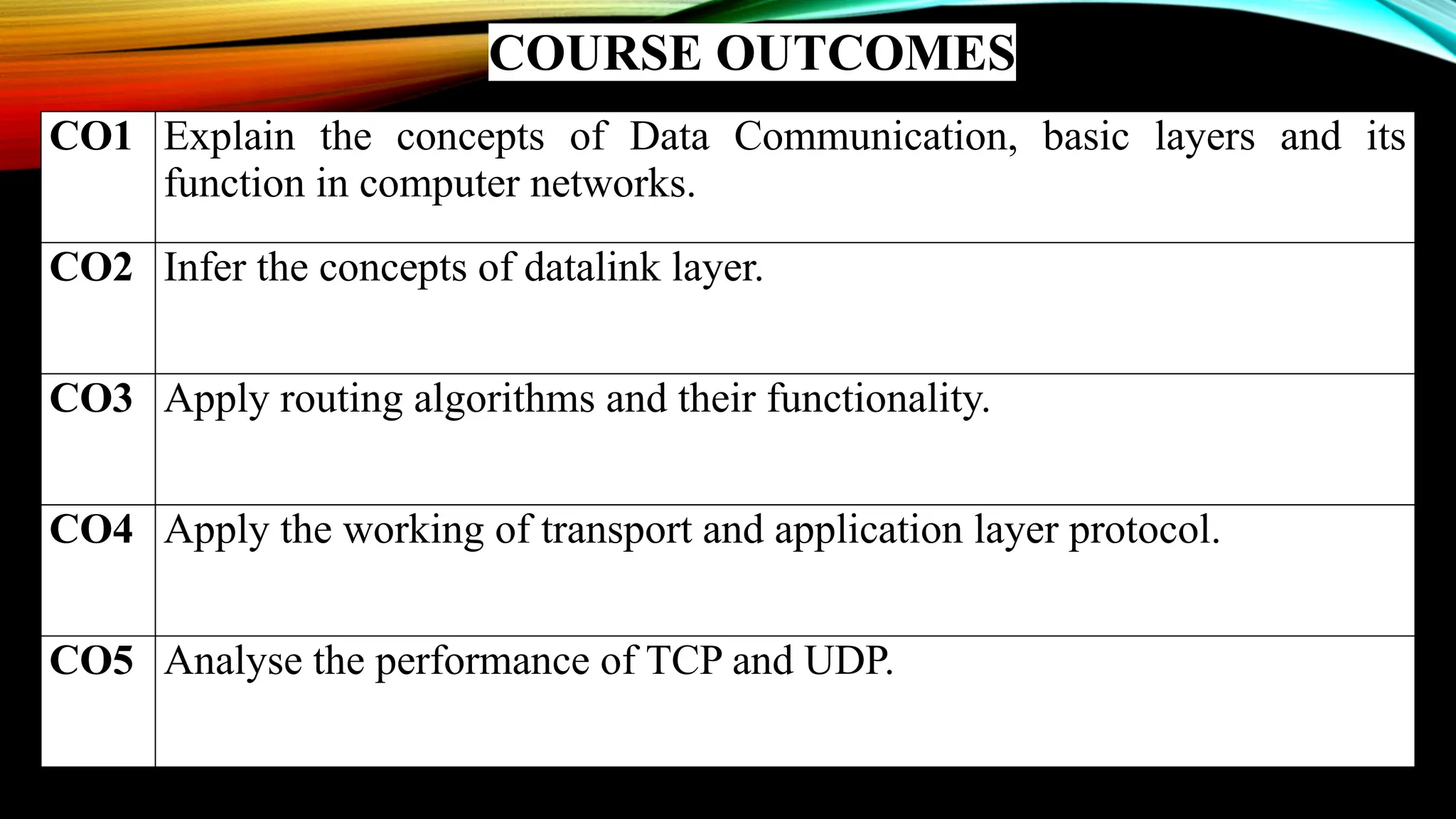
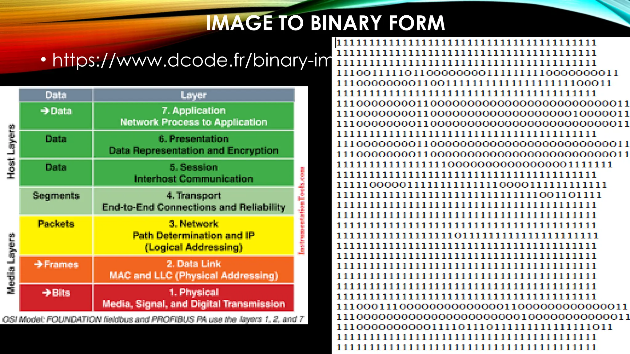
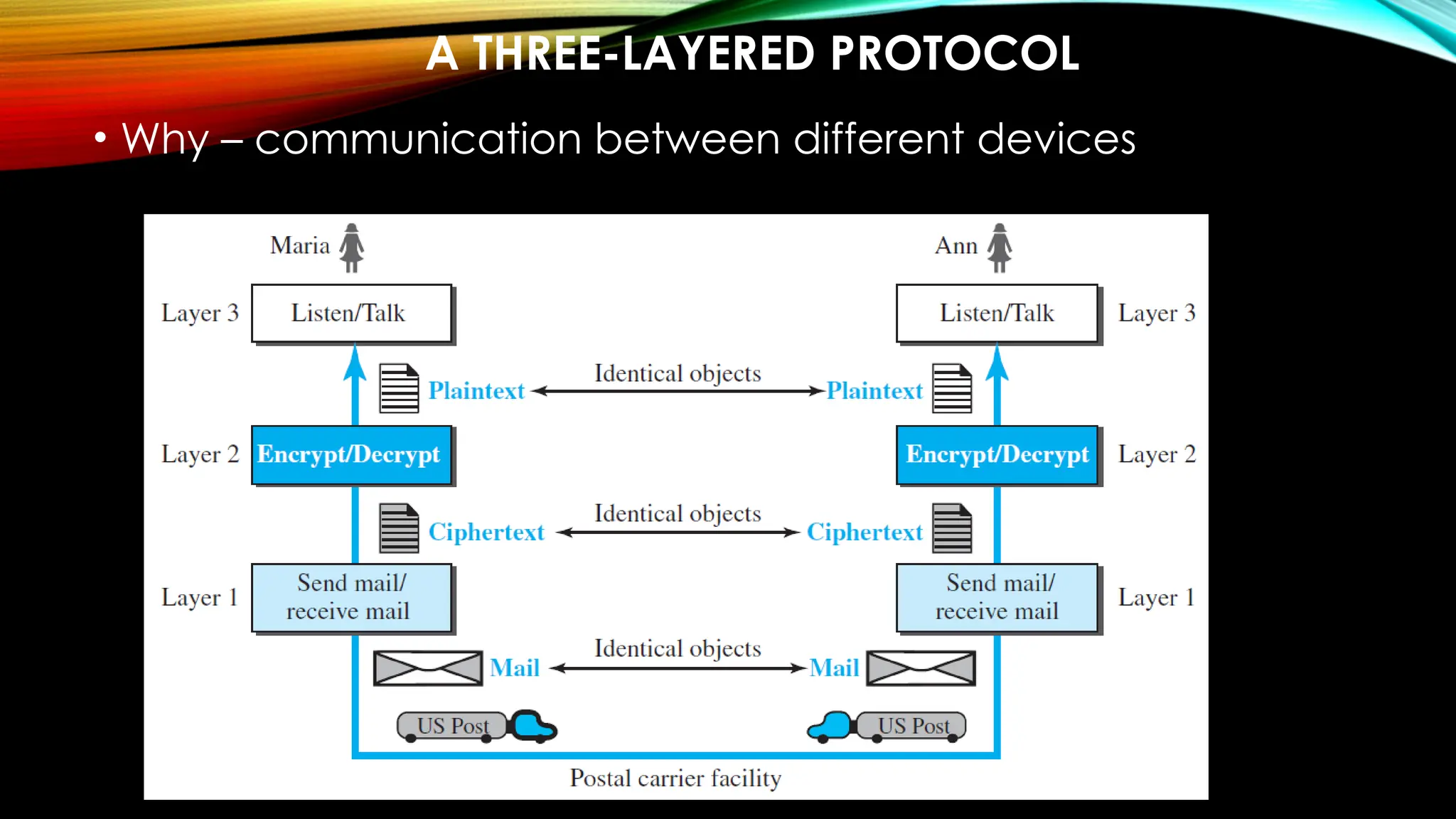
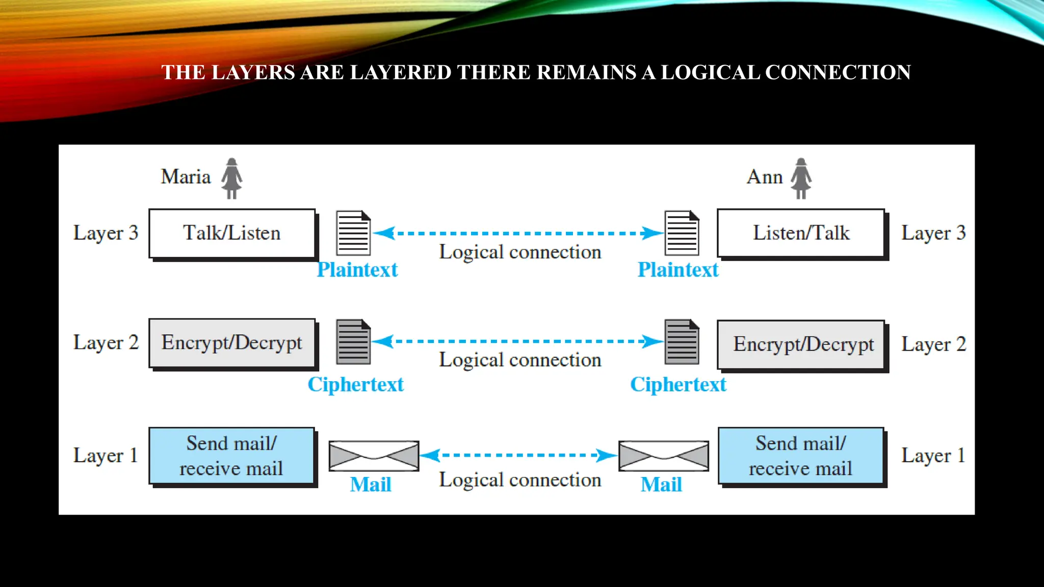
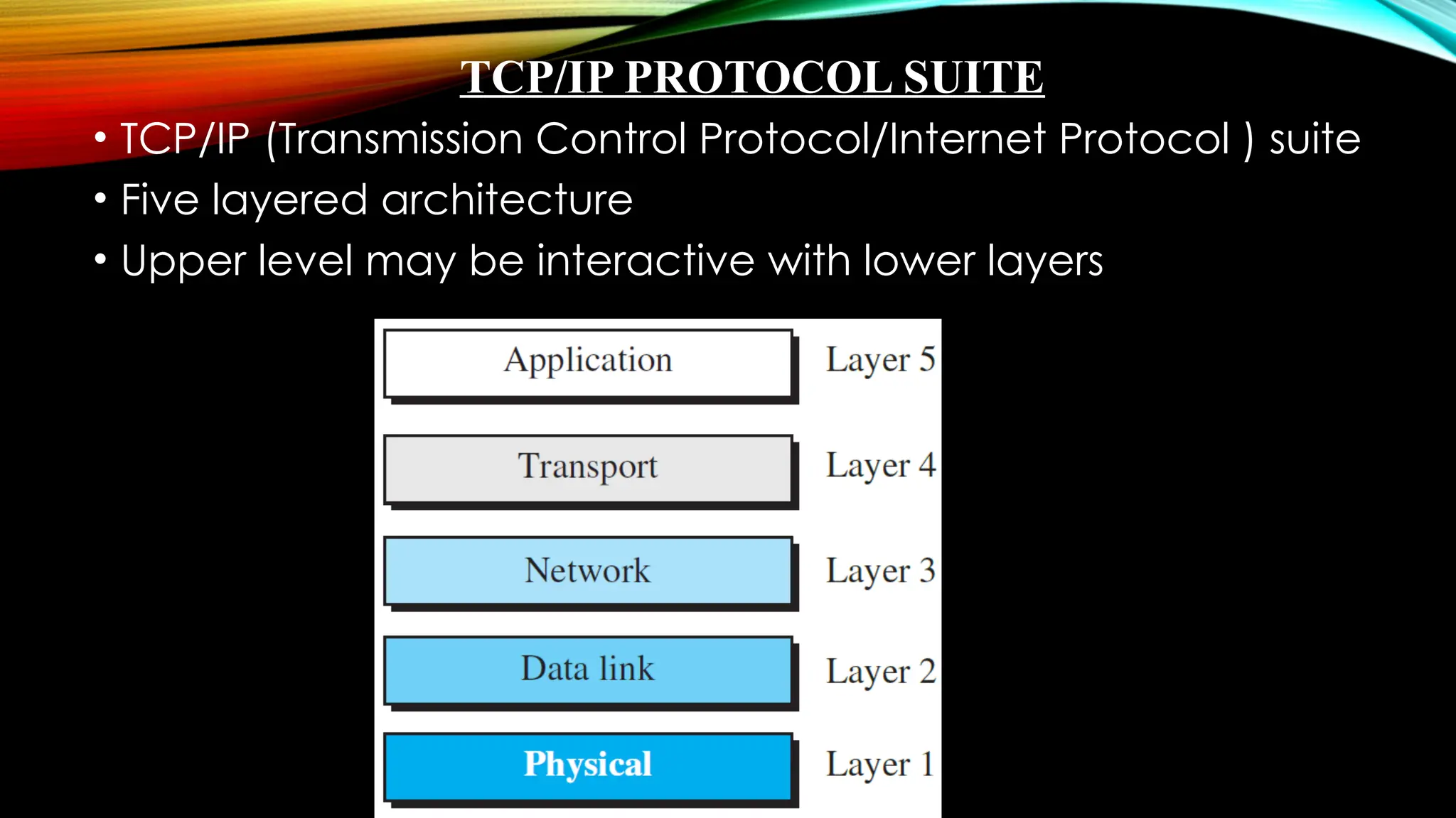
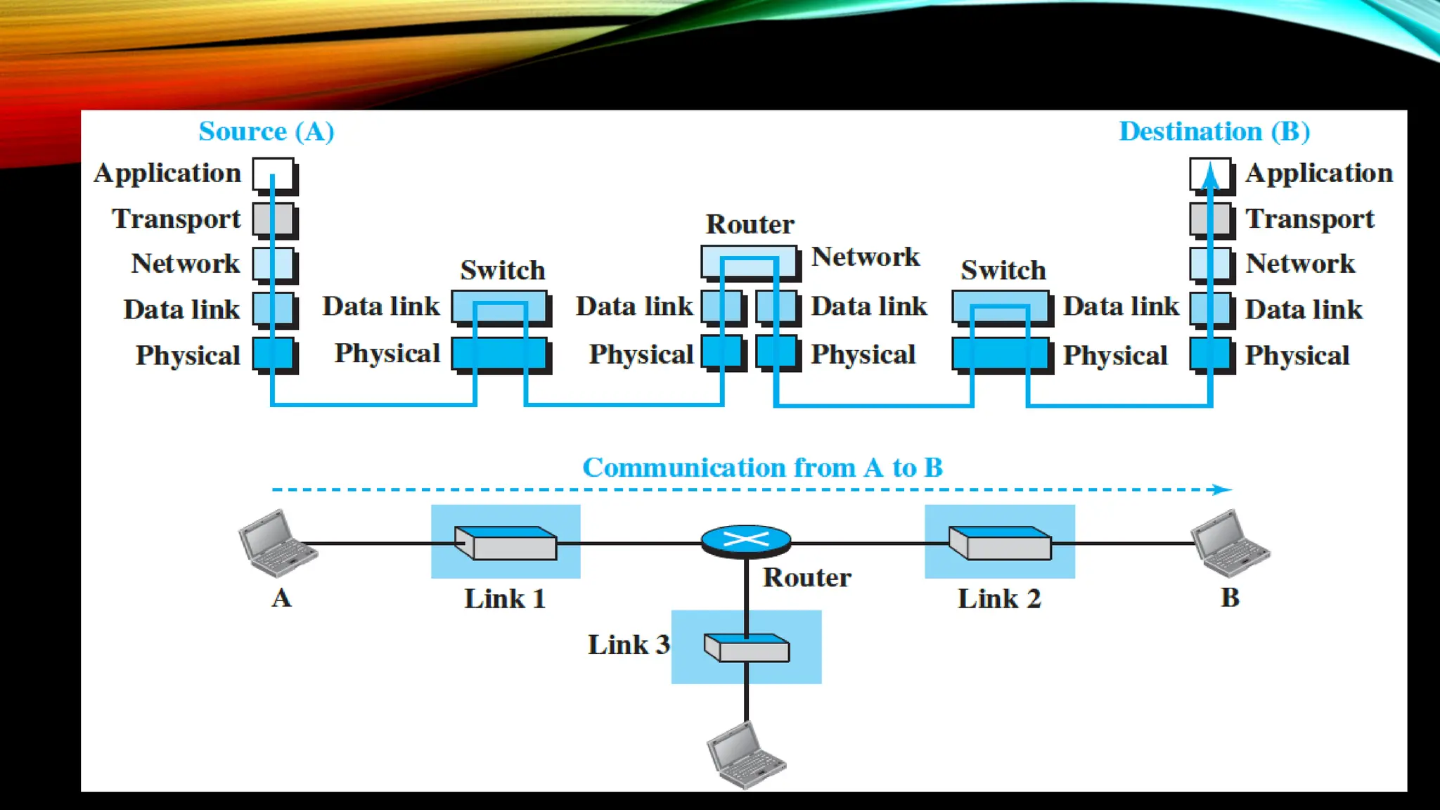
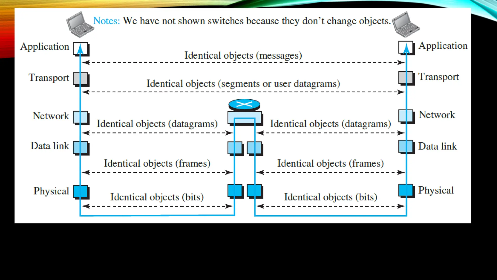
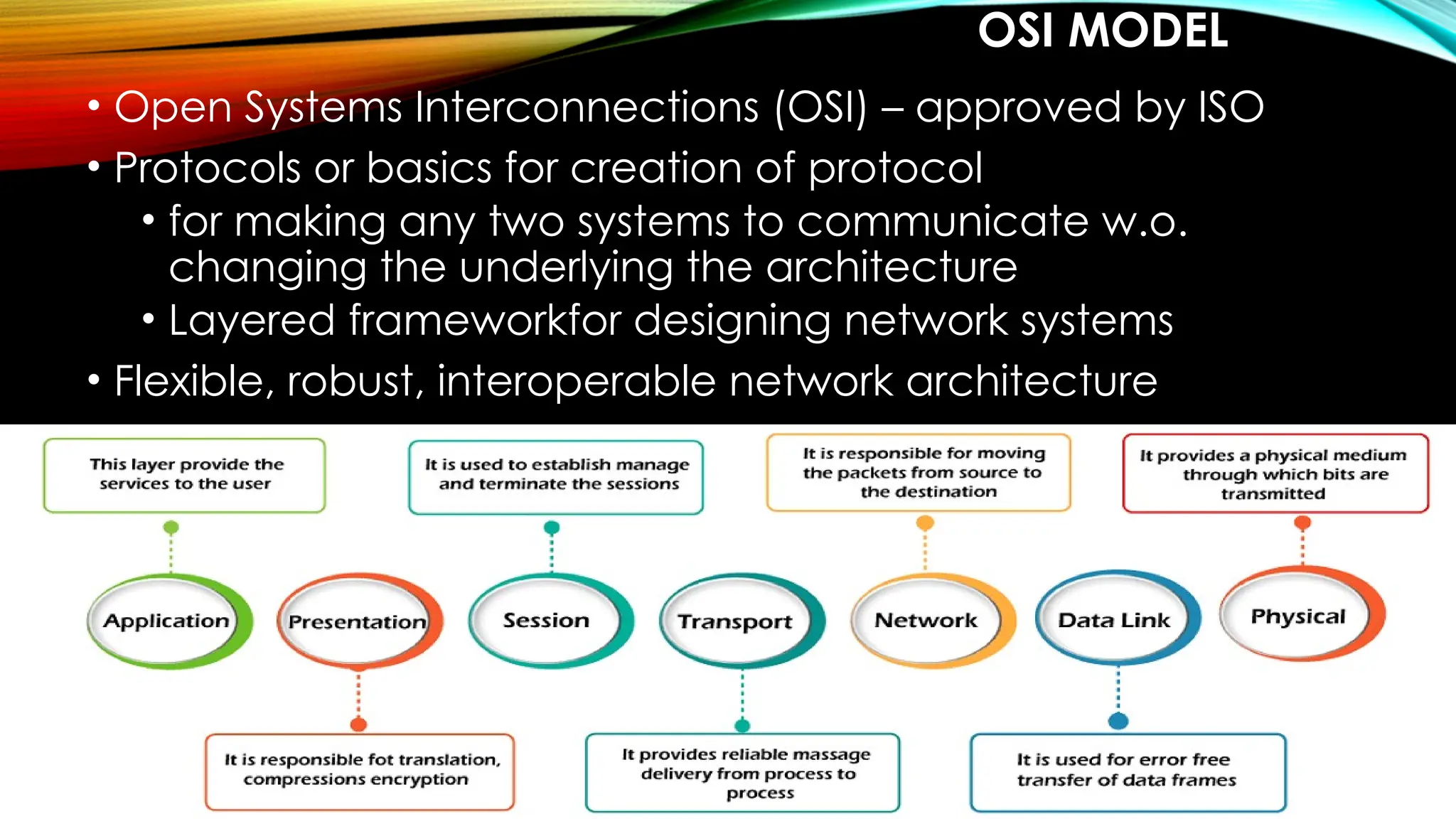
IT22501 – DATA
COMMUNICATION AND
NETWORKING
Introducing the Subject
COURSE OBJECTIVE
• To understand the protocol layering.
• To analyze the performance of the Networks.
• To understand the various components required to build
different networks.
• To learn function of a network layer.
• To familiarize the functions and protocols of the transport
layer.
UNIT I
UNIT I INTRODUCTION AND PHYSICAL LAYER 6
Networks – Network Types – Protocol Layering – TCP/IP Protocol suite –
OSI Model – Physical Layer: Performance – Transmission media : Guided
media-Unguided media: Wireless– Switching.
UNIT II
UNIT II DATALINK LAYER 6
Introduction-nodes and link-Two types of links-Two sublayers -Data link
control: Framing-Error Control-Two DLC protocols – Link-Layer Addressing
– DLC Services – Data-Link Layer Protocols – HDLC.
UNIT III
UNIT IV
UNIT III NETWORK LAYER 6
Network Layer Services: Packetizing-Routing-Error Control-Flow Control-
Congestion Control quality of service-Network layer performance: Delay-
Throughput-packet loss – Packet switching – Performance – IPV4 Addresses –
Forwarding of IP Packets – Network Layer Protocols: IP, ICMP v4.
UNIT IV TRANSPORT LAYER 6
Introduction – Transport Layer Protocols: Services – Port Numbers – User
Datagram Protocol: UDP services-UDP applications-Transmission control
protocol: TCP services-TCP features Segment-A TCP connection-State
Transition Diagram-SCTP: SCTP services-SCTP features.
UNIT V
UNIT V APPLICATION LAYER 6
WWW and HTTP – FTP – Email –Telnet-Secure Shell (SSH)-Domain
Name System(DNS).
COURSE OUTCOMES
CO1 Explain the concepts of Data Communication, basic layers and its
function in computer networks.
CO2 Infer the concepts of datalink layer.
CO3 Apply routing algorithms and their functionality.
CO4 Apply the working of transport and application layer protocol.
CO5 Analyse the performance of TCP and UDP.
BOOKS
TEXT BOOKS
1. Behrouz A. Forouzen, “Data Communications and Networking with
TCP/IP Protocol Suite”, Sixth Edition, TMH,2022
2. William Stallings, “Data and Computer Communications”, Eighth Edition,
Pearson Education, 2023.
REFERENCE BOOKS
1. Larry Peterson, Bruce S. Davie, “Computer Networks: A system
Approach”, Fifth Edition, Morgan Kaufmann Publishers Inc , 2012
2. Doug Lowe, “Networking all-in one Dummies”, Seventh Edition, Wiley
Publication, 2018.
3. Nader F. Mir, “Computer and Communication Networks”, Second Edition,
Prentice hall, 2015.
4. Ying-Dar Lin, Ren-Hung Hwang and Fred Baker, “Computer Networks: An
open Source Approach”, McGraw Hill Publishers, 2011.
WHAT IS NETWORKING?
Lets see a demo video on how data travels in the network…. -
VIDEO
IT22501 – DATA
COMMUNICATION AND
NETWORKING
Unit I – Introduction and Physical Layer
INTRODUCING NETWORK
• Data – Any Information
• Data Communication – exchange of data – two devices –
via transmission medium – supporting software
• Characteristics of Network:
• Delivery – to intended device
• Accuracy – messages cannot be altered or corrected
• Timeliness – a late data is useless
• Jitter – variation in packet arrval
COMPONENTS OF DATA COMMUNICATION
DATA REPRESENTATION
• Text – 0s and 1s – codes
• Unicode – 32-bit
• ASCII – 7-bit
• Numbers –
• Images –
• Audio –
• Video -
UNI CODE
ASCII CODE
IMAGE TO BINARY FORM
• https://www.dcode.fr/binary-image
• Audio to Binary - https://openl.io/translate/mp3/binary
• Video to Binary -
https://base64.guru/converter/encode/video
DATA FLOW
NETWORK
• Interconnection of communicating devices
• Host – end system
• Connecting device – network to network
• Modem – change the form of data
NETWORK CRITERIA
• Performance – measured with
• Transit time – time travel of message from one device to
another
• Response time – elapsed time between an inquiry and a
response
• Throughput – volume of data into the network in a time
• Delay or latency – delay or actual time for
communicating a data
• Reliability – time taken to recover from a failure
• Security – protecting
PHYSICAL STRUCTURES
• Point-to-point – dedicated b/w 2 devices
• Multipoint – or multidrop – spatial or temporal
PHYSICAL TOPOLOGY – MESH
• Topology is the way devices are connected to one another
• In mesh – simplex – n(n-1)
• - duplex – n(n-1)/2
• Advantages:
o Dedicated links
o Robustness - if one link is unusable, it does not disturb the network or
other connections
o Privacy and security of data is ensured make fault identification and
fault isolation easy
• Disadvantages:
o huge amount of cabling and IO ports required as there is dedicated
connection between every device
o huge space is required for keeping the connections
o the hardware requirement makes the installation costly
STAR TOPOLOGY
• dedicated point-to-point link to hub
Advantages:
o It is less expensive than mesh
o easy to install, configure and less cabling
o Robust, easy in fault detection and isolation
Disadvantages:
o All the connections depend on hub, failure of hub will fail the entire
system.
o It requires more cabling than ring and bus topology
BUS TOPOLOGY
• multipoint in which one cable act as a backbone – dropline and taps
Advantages:
• Efficient installation
Disadvantages:
the main cable travels long, so the signals become weaker and weaker
a limit on the number of taps
Difficult reconnection and fault isolation
Difficult to add new devices as it requires modification and replacement
Signal reflection at the taps can cause degradation in quality
a fault or break in the bus cable stops all transmission
RING TOPOLOGY
Advantages:
• Easy to install and reconfigure as each device
• Fault isolation is simplified
Disadvantages:
a break in the ring can disable the entire network
NETWORK TYPES - LAN
• Private network at least with 2 or more host
• Each having an address
• Packet from one host to another host has both source and
destination address
• LAN uses connecting switches for guiding packets towards
destination
• LAN switch advantages
• Eliminates traffic
• Multipoint communication
LAN
WAN
• To connect to wider areas
• Connecting devices
• Switch
• Router
• modems
• Types
• Point-to-Point WAN
• Switched WAN
POINT-TO-POINT WAN
• Network for two communicating devices
SWITCHED WAN
• More than two ends
• Combination of many point-to-point WAN
INTERNETWORK
• LAN and WAN connected to form internet
HETEROGENEOUS NETWORK MADE OF FOUR WANS AND THREE LANS
INTERNET
INTERNET
• Backbone or ISPs – large network owned by BSNL,
starlink etc. and are connected via complex
switching system called – peering points
• Provider networks – uses the service backbone for
fee
• Customer network – edge users
ACCESSING THE INTERNET
• Using telephone networks
• Dial-up services – add modem to telephone –
• Computer software for dialing to internet
• Slow and cant access internet when using phone
• DSL (digital subscriber line
• Simultaneous data and voice communication
USING CABLE NETWORK
• TV lines extended for internet
• Speed varies depending on the users in the same
cable
USING WIRELESS NETWORKS
• WWAN – cellular technology
• Components
• Router
• Cellular network
• SIM card
• Cloud management tool
DIRECT CONNECTION TO INTERNET
PROTOCOL LAYERING
• Protocol – rules for sending and receiving devices for
effective communication
• Protocol layering - Layers to split the task for communication
• Single layered protocol
• Handshake
• Bidirectional communication
• Pre-defined communication language
A THREE-LAYERED PROTOCOL
• Why – communication between different devices
LAYERED ARCHITECTURE - ELEMENTS
Service − Set of actions or services provided from one
layer to the higher layer.
Protocol − It defines a set of rules where a layer uses to
exchange the information with its peer entity. It is
concerned about both the contents and order of the
messages used.
Interface − It is a way through that the message is
transferred from one layer to another layer.
• Reason – Layered Architecture
• Well-defined interface between layers
• Feasible implementation
• Advantages
• Each layer is assisted with a protocol
• products from completely different vendors will work along
• Prevents technology or capability changes
• typical language to explain networking functions and capabilities
Disadvantages:
• layered systems are the abstraction barriers between layers
• The upper-level layers cannot see what is within the lower layers
i.e. no connections can be made
• The higher-level layers cannot control all aspects of the lower layers
THE LAYERS ARE LAYERED THERE REMAINS A LOGICAL CONNECTION
TCP/IP PROTOCOL SUITE
• TCP/IP (Transmission Control Protocol/Internet Protocol ) suite
• Five layered architecture
• Upper level may be interactive with lower layers
BASIC ELEMENTS OF LAYERED ARCHITECTURE
Service − Set of actions or services provided from one layer to
the higher layer.
Protocol − It defines a set of rules where a layer uses to
exchange the information with its peer entity. It is concerned
about both the contents and order of the messages used.
Interface − It is a way through that the message is transferred
from one layer to another layer.
REASON FOR LAYERING
• well-defined interfaces between the layers
• designing them in layers makes their implementation more
feasible
Advantages:
• a defined interface to the layers
• products from completely different vendors will work
along
• Prevents technology or capability changes
• a typical language to explain networking functions
and capabilities
Disadvantages:
• layered systems are the abstraction barriers between layers
• The upper-level layers cannot see what is within the lower layers
• The higher-level layers cannot control all aspects of the lower layers
• duty of the top three layers is the internet, and the domain of duty of the
two lower layers is the link
• data-link and physical layers is hop-to-hop
• Top three – packets are not changed
• Bottom two layers – packets are changed
TCP/IP SUITE LAYER DESCRIPTION
Physical Layer – is the lowest level and is for carrying individual
bits in a frame across the link.
o the communication between two devices at the
physical layer is still a logical communication because there is
another hidden layer, the transmission media, under the
physical layer.
Data-link Layer – is responsible for taking the datagram and
moving it across the link.
o An internet is made up of several links (LANs and WANs)
connected by routers that determines the next link to be
travelled.
Network Layer – is for creating a connection between the source and
destination computers and is a host-to-host communication.
o The routers in the path chooses the best route for each packet.
Transport Layer – has a logical end-to-end connection between the
hosts.
o At the source it gets the message from the application layer;
encapsulates it in a transport-layer packet (called a segment or a user
datagram in different protocols); and sends it, through the logical
(imaginary) connection, to the transport layer at the destination host.
o i.e., the transport layer is responsible for giving services to the
application layer: to get a message from an application program
running on the source host and deliver it to the corresponding
application program on the destination host.
Application Layer – also has the logical end-to-end
connection i.e., is a process-to-process communication.
o Though the communication is done through all layers,
the two application layers exchange messages between
each other as though there were a bridge between them.
o Communication at the application layer is between two
processes.
 a process sends a request to the other process and
receives a response.
OSI MODEL
• Open Systems Interconnections (OSI) – approved by ISO
• Protocols or basics for creation of protocol
• for making any two systems to communicate w.o.
changing the underlying the architecture
• Layered frameworkfor designing network systems
• Flexible, robust, interoperable network architecture
1. PHYSICAL LAYER
It is the lowest layer of the OSI model.
Main functionality
to transmit the individual bits from one node to another node.
It establishes, maintains and deactivates the physical
connection.
the mechanical, electrical and procedural network interface
specifications.
Functionality
Line configuration – physical connection between devices
Data transmission mode - ……..
(simplex, half-duplex, full-duplex)
Topology -
Signals – analog or digital
DATA-LINK LAYER
• It is for efficient and reliable communication
Functionalities:
• Error-free data frames transfer
• Defines the format of data
• the unique identification of each device that resides on a
local network
Sub-layers:
 Logical link control layer
 Responsible for transferring packets to n/w layer
 Identifies address of n/w layer protocol
 Provides flow control
 Media Access Control Layer
 Connects Links logical link and physical layer
 Transfers the packet
Functionality
• Framing – bits to frames, adds header and trailer – has both
source and destination address
• Physical Addressing – destination address on the header
• Flow control – maintain a constant data rate on both side
• Error control – CRC added to the frame’s trailer – if error
found then retransmission of packets
• Access control – priority of devices in the channel
NETWORK LAYER
• Manages
• device addressing
• Location tracking
• Choosing best path from source to destination – n/w
condition, priority
• Device – router
• Network layer protocols – IPv4 and IPv6
Functions:
• Internetworking – logical connection between devices
• Addressing – hopping addresses
• Routing – finding best route
• Packetizing – frames to packets with IP
TRANSPORT LAYER
• Ensures messages are transmitted completely
• the same order they are sent
• No duplication of data
• Convert data received to segments
• Called as end-to-end layers – i.e. point-to-point connection
• Involves 2 protocols
• TCP
• Systems for communication – establishes connection between
hosts – reliable protocol
• UDP
• Unreliable
Functions:
• Service-point addressing – adding service point address or
port number to identify the process in the destination device
• Segmentation and reassembling –
• messages from upper layer is segmented and unique
sequence number is given
• At the destination device the segments are ordered
according to the sequence number
• Connection control –
• Connection-oriented service – establishes a connection ,
all packets travel in the same route
• Connectionless service – no established connection -
each packet travels into any possible route to reach the
destination
• Flow control – in end-to-end and not point-to-point
• Error control – end-to-end – messages are send without any
error
SESSION LAYER
• establish, maintain and synchronizes the interaction between
communicating devices
Functions:
 Dialog control – creates dialog between processes in full or
half-duplex modes
 Synchronization or recovery – adding checkpoints –
retransmission of data if some errors in transmission
PRESENTATION LAYER
• Syntax and semantics of data
• Network translator in OS for converting data from one format
to another format
Functions:
• Translation – end processes have different encoding
methods
• Conversion from sender-dependent to common
• Common to receiver dependent
• Encryption – senders message encrypted – receiver decrypts
• Compression – reducing the number of bits to be transfered
APPLICATION LAYER
• as a window for users and application processes to access
network service
• Handles – network transparency, resource allocation, etc.,
Functions:
• FTAM – allows
• access the files in a remote computer,
• to retrieve the files from a computer and
• to manage the files in a remote computer.
• Mail services – email forwarding and storing
• Directory services – distributed database sources
PHYSICAL LAYER: PERFORMANCE
1. Bandwidth
Bandwidth in Hertz – range of frequencies a channel can pass. In a
telephone line – 4kHz
Bandwidth in bps – the bits a channel can transfer . In ethernet 100
Mbps
Mbps To Hz Formula
The following formula is used to convert Mbps to Hz.
F=(C)/Modulation
Variables:
F is the frequency bandwidth (Hz)
C is the data rate (Megabits per second)
Modulation is the number of bits per Hz of bandwidth =14
Example: The bandwidth of a subscriber line is 4 kHz for
voice or data.
C=F*Modulation
C=4kHz*14=4000Hz*14 = 56000
The bandwidth of this line for data transmission can be up
to 56,000 bps using a sophisticated modem to change the
digital signal to analog.
Example: If the telephone company improves the quality of
the line and increases the bandwidth to 8 kHz, we can send
112,000 bps using a sophisticated modem to change the
digital signal to analog.
THROUGHPUT
• measure of how fast we can actually send data through a
network
• Example – a link with a bandwidth of 1 Mbps, but the
devices connected to the end of the link may handle only
200 kbps. This means that we cannot send more than 200
kbps through this link.
Example - A network with bandwidth of 10 Mbps can pass
only an average of 12,000 frames per minute with each frame
carrying an average of 10,000 bits. What is the throughput of
this network?
Solution:
Data frames in the network = 12000 per min
1 frame = 10000
Therefore,
Bits in the network per minute i.e., throughput in a min = 12000
x 10000
Throughput in a second =(12000 X 10000)/60 = 2000000 bps =
2 Mbps (1 Mbps = 1000000 bps)
Example - What is the propagation time if the distance
between the two points is 12,000 km? Assume the
propagation speed to be 2.4 × 10^8 m/s in cable.
Solution - Propagation time = (12,000 x 1000) / (2.4 x 10^8) =
0.05 seconds = 50 ms (1 s = 1000 ms millisecond)
Transmission time – of a message depends on the size of the
message and the bandwidth of the channel.
Transmission time = (Message size) / Bandwidth
Example - What are the propagation time and the
transmission time for a 2.5-KB (kilobyte) message (an email) if
the bandwidth of the network is 1 Gbps? Assume that the
distance between the sender and the receiver is 12,000 km
and that light travels at 2.4 × 10^8 m/s.
Solution – Propagation time = (12,000 x 1000) / (2.4 x 10⁸) =
0.05 s = 50 ms
2.5 KB = 2500 bytes = 2500 X 8 bits
1 Gbps = 10^9 bits
Transmission time = (2500 x 8) / 10^9 =20000 /1000000000
= .00002 s = 0.020 ms
1.7. TRANSMISSION MEDIA
• Carry information from source to destination – physical layer
and layer 0
TX. MEDIUM
• Free space, cable – metallic, fiber optics
• Information – in signal form
• Mediums – twisted pair, coaxial, optical fiber, air, vacuum
• Signals – electromagnetic energy – electric + magnetic – a
portion of the spectrum
GUIDED MEDIA
• twisted-pair cable, coaxial cable, and fiber-optic cable
• Physical mediums have their own limits
• twisted-pair cable, coaxial cable – signal in form of electric
current
• Optical fiber – form of light
TWISTED PAIR
• Two conductors with plastic insulation - twisted together
• One – carry signal to the receiver
• Other – ground reference
• Noise – twisted – let the noise do not affect
• Number of twists has effect on quality
UNSHIELDED TWISTED-PAIR (UTP) VS SHIELDED TWISTED-PAIR (STP) CABLE
UTP STP
UTP stands for Unshielded Twisted Pair. STP stands for Shielded Twisted Pair.
UPP do not have any shields around it. STP cable has a metal foil or braided mesh
covering that encases each pair of insulated
conductors
In UTP grounding cable is not necessary. While in STP grounding cable is required.
Data rate in UTP is slow compared to STP. Data rate in STP is high.
The cost of UTP is less. While STP is costlier than UTP.
In UTP much more maintenance is not
needed.
While in STP much more maintenance is needed.
In UTP noise is high compared to STP. While in STP noise is less.
• Used in telephone lines and data channel
• Line connecting subscriber to central telephone office
• High data rate
• LAN
COAXIAL CABLES
• Wire – insulator – metal braid – plastic cover
Performance
• High bandwidth
• Signals get weaker rapidly
• Therefore need repeaters
• High attenuation than twisted pair
Application
• High capacity telephone lines (10000 voice signals,
• Cable TV RG59
• LAN ethernet
FIBER OPTICS
• A glass or fiber as a single medium
• Surrounded by cladding of glass or plastic
Performance
• Attenuation is much less
Application
• Wider bandwidth
• Cable TVs
UNGUIDED MEDIA – WIRELESS COMMUNICATION
• No physical medium or conductors
• Uses free spaces
• Radio wave, Micro wave Infra Red
RADIO WAVE
• Electromagnetic spectrum – 3 kHz to 900 THz
• 3 kHz – 1 GHz – normal radio wave
• Omnidirectional
• Under 1 GHz – divided into sub bands
Disadvantages
• As omni – waves from different antenna may create
interference
• Cannot be isolated for inside and outside the building
Advantages
• Used for broadcasting
• Received inside a building
MICROWAVE
• Unidirectional EM waves
• 1GHz to 300GHz
• Narrow focusing – as unidirectional aligned without
interference
• Obstacles prevents communication
• Making wider sub-bands
Disadvantages
• Cannot penetrate wall
• Restricted – permission from authorities
Application
• Unicast – Cellphones, satilite networks, wireless LANs
INFRARED
• 300 GHz to 400 THz
Advantages:
• Prevents inference
Disadvantages
• Only for short rage communication
• Cannot be used under sun rays
Application
• Remote controls
SWITCHING
• Switch – connect two or more links
• Switching – transfer data packets / blocks via switches
• It prevents traffic
• Has information of devices connected to it  easy
forwarding of packets
Types
• Circuit-switched
• Packet-switched
CIRCUIT-SWITCHED NETWORK
• A dedicated connection called circuit between two devices
• Switch decides on active or inactive mode
• Is efficient when working in full capacity
PACKET SWITCHING
• Two ends connected via packets
• No continuous communication
• ROUTER – device
• Stores and forwards packets
• Capacity of communication is doubled
• Packets do not wait – point-to-point communication, else
waits
• Efficient than circuit switch
Data Structures unit I just look to learn the contents

Data Structures unit I just look to learn the contents

  • 1.
    IT22501 – DATA COMMUNICATIONAND NETWORKING Introducing the Subject
  • 2.
    COURSE OBJECTIVE • Tounderstand the protocol layering. • To analyze the performance of the Networks. • To understand the various components required to build different networks. • To learn function of a network layer. • To familiarize the functions and protocols of the transport layer.
  • 3.
    UNIT I UNIT IINTRODUCTION AND PHYSICAL LAYER 6 Networks – Network Types – Protocol Layering – TCP/IP Protocol suite – OSI Model – Physical Layer: Performance – Transmission media : Guided media-Unguided media: Wireless– Switching. UNIT II UNIT II DATALINK LAYER 6 Introduction-nodes and link-Two types of links-Two sublayers -Data link control: Framing-Error Control-Two DLC protocols – Link-Layer Addressing – DLC Services – Data-Link Layer Protocols – HDLC.
  • 4.
    UNIT III UNIT IV UNITIII NETWORK LAYER 6 Network Layer Services: Packetizing-Routing-Error Control-Flow Control- Congestion Control quality of service-Network layer performance: Delay- Throughput-packet loss – Packet switching – Performance – IPV4 Addresses – Forwarding of IP Packets – Network Layer Protocols: IP, ICMP v4. UNIT IV TRANSPORT LAYER 6 Introduction – Transport Layer Protocols: Services – Port Numbers – User Datagram Protocol: UDP services-UDP applications-Transmission control protocol: TCP services-TCP features Segment-A TCP connection-State Transition Diagram-SCTP: SCTP services-SCTP features.
  • 5.
    UNIT V UNIT VAPPLICATION LAYER 6 WWW and HTTP – FTP – Email –Telnet-Secure Shell (SSH)-Domain Name System(DNS).
  • 6.
    COURSE OUTCOMES CO1 Explainthe concepts of Data Communication, basic layers and its function in computer networks. CO2 Infer the concepts of datalink layer. CO3 Apply routing algorithms and their functionality. CO4 Apply the working of transport and application layer protocol. CO5 Analyse the performance of TCP and UDP.
  • 7.
    BOOKS TEXT BOOKS 1. BehrouzA. Forouzen, “Data Communications and Networking with TCP/IP Protocol Suite”, Sixth Edition, TMH,2022 2. William Stallings, “Data and Computer Communications”, Eighth Edition, Pearson Education, 2023. REFERENCE BOOKS 1. Larry Peterson, Bruce S. Davie, “Computer Networks: A system Approach”, Fifth Edition, Morgan Kaufmann Publishers Inc , 2012 2. Doug Lowe, “Networking all-in one Dummies”, Seventh Edition, Wiley Publication, 2018. 3. Nader F. Mir, “Computer and Communication Networks”, Second Edition, Prentice hall, 2015. 4. Ying-Dar Lin, Ren-Hung Hwang and Fred Baker, “Computer Networks: An open Source Approach”, McGraw Hill Publishers, 2011.
  • 8.
    WHAT IS NETWORKING? Letssee a demo video on how data travels in the network…. - VIDEO
  • 9.
    IT22501 – DATA COMMUNICATIONAND NETWORKING Unit I – Introduction and Physical Layer
  • 10.
    INTRODUCING NETWORK • Data– Any Information • Data Communication – exchange of data – two devices – via transmission medium – supporting software • Characteristics of Network: • Delivery – to intended device • Accuracy – messages cannot be altered or corrected • Timeliness – a late data is useless • Jitter – variation in packet arrval
  • 11.
    COMPONENTS OF DATACOMMUNICATION
  • 12.
    DATA REPRESENTATION • Text– 0s and 1s – codes • Unicode – 32-bit • ASCII – 7-bit • Numbers – • Images – • Audio – • Video -
  • 13.
  • 15.
  • 16.
    IMAGE TO BINARYFORM • https://www.dcode.fr/binary-image
  • 17.
    • Audio toBinary - https://openl.io/translate/mp3/binary • Video to Binary - https://base64.guru/converter/encode/video
  • 18.
  • 19.
    NETWORK • Interconnection ofcommunicating devices • Host – end system • Connecting device – network to network • Modem – change the form of data
  • 21.
    NETWORK CRITERIA • Performance– measured with • Transit time – time travel of message from one device to another • Response time – elapsed time between an inquiry and a response • Throughput – volume of data into the network in a time • Delay or latency – delay or actual time for communicating a data • Reliability – time taken to recover from a failure • Security – protecting
  • 22.
    PHYSICAL STRUCTURES • Point-to-point– dedicated b/w 2 devices • Multipoint – or multidrop – spatial or temporal
  • 23.
    PHYSICAL TOPOLOGY –MESH • Topology is the way devices are connected to one another • In mesh – simplex – n(n-1) • - duplex – n(n-1)/2
  • 24.
    • Advantages: o Dedicatedlinks o Robustness - if one link is unusable, it does not disturb the network or other connections o Privacy and security of data is ensured make fault identification and fault isolation easy • Disadvantages: o huge amount of cabling and IO ports required as there is dedicated connection between every device o huge space is required for keeping the connections o the hardware requirement makes the installation costly
  • 25.
    STAR TOPOLOGY • dedicatedpoint-to-point link to hub Advantages: o It is less expensive than mesh o easy to install, configure and less cabling o Robust, easy in fault detection and isolation Disadvantages: o All the connections depend on hub, failure of hub will fail the entire system. o It requires more cabling than ring and bus topology
  • 26.
    BUS TOPOLOGY • multipointin which one cable act as a backbone – dropline and taps Advantages: • Efficient installation Disadvantages: the main cable travels long, so the signals become weaker and weaker a limit on the number of taps Difficult reconnection and fault isolation Difficult to add new devices as it requires modification and replacement Signal reflection at the taps can cause degradation in quality a fault or break in the bus cable stops all transmission
  • 27.
    RING TOPOLOGY Advantages: • Easyto install and reconfigure as each device • Fault isolation is simplified Disadvantages: a break in the ring can disable the entire network
  • 28.
    NETWORK TYPES -LAN • Private network at least with 2 or more host • Each having an address • Packet from one host to another host has both source and destination address • LAN uses connecting switches for guiding packets towards destination • LAN switch advantages • Eliminates traffic • Multipoint communication
  • 29.
  • 30.
    WAN • To connectto wider areas • Connecting devices • Switch • Router • modems • Types • Point-to-Point WAN • Switched WAN
  • 31.
    POINT-TO-POINT WAN • Networkfor two communicating devices
  • 32.
    SWITCHED WAN • Morethan two ends • Combination of many point-to-point WAN
  • 33.
    INTERNETWORK • LAN andWAN connected to form internet
  • 34.
    HETEROGENEOUS NETWORK MADEOF FOUR WANS AND THREE LANS
  • 35.
  • 36.
    INTERNET • Backbone orISPs – large network owned by BSNL, starlink etc. and are connected via complex switching system called – peering points • Provider networks – uses the service backbone for fee • Customer network – edge users
  • 37.
    ACCESSING THE INTERNET •Using telephone networks • Dial-up services – add modem to telephone – • Computer software for dialing to internet • Slow and cant access internet when using phone • DSL (digital subscriber line • Simultaneous data and voice communication
  • 38.
    USING CABLE NETWORK •TV lines extended for internet • Speed varies depending on the users in the same cable
  • 39.
    USING WIRELESS NETWORKS •WWAN – cellular technology • Components • Router • Cellular network • SIM card • Cloud management tool
  • 40.
  • 41.
    PROTOCOL LAYERING • Protocol– rules for sending and receiving devices for effective communication • Protocol layering - Layers to split the task for communication • Single layered protocol • Handshake • Bidirectional communication • Pre-defined communication language
  • 42.
    A THREE-LAYERED PROTOCOL •Why – communication between different devices
  • 43.
    LAYERED ARCHITECTURE -ELEMENTS Service − Set of actions or services provided from one layer to the higher layer. Protocol − It defines a set of rules where a layer uses to exchange the information with its peer entity. It is concerned about both the contents and order of the messages used. Interface − It is a way through that the message is transferred from one layer to another layer.
  • 44.
    • Reason –Layered Architecture • Well-defined interface between layers • Feasible implementation • Advantages • Each layer is assisted with a protocol • products from completely different vendors will work along • Prevents technology or capability changes • typical language to explain networking functions and capabilities Disadvantages: • layered systems are the abstraction barriers between layers • The upper-level layers cannot see what is within the lower layers i.e. no connections can be made • The higher-level layers cannot control all aspects of the lower layers
  • 45.
    THE LAYERS ARELAYERED THERE REMAINS A LOGICAL CONNECTION
  • 46.
    TCP/IP PROTOCOL SUITE •TCP/IP (Transmission Control Protocol/Internet Protocol ) suite • Five layered architecture • Upper level may be interactive with lower layers
  • 49.
    BASIC ELEMENTS OFLAYERED ARCHITECTURE Service − Set of actions or services provided from one layer to the higher layer. Protocol − It defines a set of rules where a layer uses to exchange the information with its peer entity. It is concerned about both the contents and order of the messages used. Interface − It is a way through that the message is transferred from one layer to another layer.
  • 50.
    REASON FOR LAYERING •well-defined interfaces between the layers • designing them in layers makes their implementation more feasible Advantages: • a defined interface to the layers • products from completely different vendors will work along • Prevents technology or capability changes • a typical language to explain networking functions and capabilities
  • 51.
    Disadvantages: • layered systemsare the abstraction barriers between layers • The upper-level layers cannot see what is within the lower layers • The higher-level layers cannot control all aspects of the lower layers
  • 52.
    • duty ofthe top three layers is the internet, and the domain of duty of the two lower layers is the link • data-link and physical layers is hop-to-hop • Top three – packets are not changed • Bottom two layers – packets are changed
  • 53.
    TCP/IP SUITE LAYERDESCRIPTION Physical Layer – is the lowest level and is for carrying individual bits in a frame across the link. o the communication between two devices at the physical layer is still a logical communication because there is another hidden layer, the transmission media, under the physical layer. Data-link Layer – is responsible for taking the datagram and moving it across the link. o An internet is made up of several links (LANs and WANs) connected by routers that determines the next link to be travelled.
  • 54.
    Network Layer –is for creating a connection between the source and destination computers and is a host-to-host communication. o The routers in the path chooses the best route for each packet. Transport Layer – has a logical end-to-end connection between the hosts. o At the source it gets the message from the application layer; encapsulates it in a transport-layer packet (called a segment or a user datagram in different protocols); and sends it, through the logical (imaginary) connection, to the transport layer at the destination host. o i.e., the transport layer is responsible for giving services to the application layer: to get a message from an application program running on the source host and deliver it to the corresponding application program on the destination host.
  • 55.
    Application Layer –also has the logical end-to-end connection i.e., is a process-to-process communication. o Though the communication is done through all layers, the two application layers exchange messages between each other as though there were a bridge between them. o Communication at the application layer is between two processes.  a process sends a request to the other process and receives a response.
  • 56.
    OSI MODEL • OpenSystems Interconnections (OSI) – approved by ISO • Protocols or basics for creation of protocol • for making any two systems to communicate w.o. changing the underlying the architecture • Layered frameworkfor designing network systems • Flexible, robust, interoperable network architecture
  • 57.
    1. PHYSICAL LAYER Itis the lowest layer of the OSI model. Main functionality to transmit the individual bits from one node to another node. It establishes, maintains and deactivates the physical connection. the mechanical, electrical and procedural network interface specifications. Functionality Line configuration – physical connection between devices Data transmission mode - …….. (simplex, half-duplex, full-duplex) Topology - Signals – analog or digital
  • 59.
    DATA-LINK LAYER • Itis for efficient and reliable communication Functionalities: • Error-free data frames transfer • Defines the format of data • the unique identification of each device that resides on a local network
  • 60.
    Sub-layers:  Logical linkcontrol layer  Responsible for transferring packets to n/w layer  Identifies address of n/w layer protocol  Provides flow control  Media Access Control Layer  Connects Links logical link and physical layer  Transfers the packet
  • 62.
    Functionality • Framing –bits to frames, adds header and trailer – has both source and destination address • Physical Addressing – destination address on the header • Flow control – maintain a constant data rate on both side • Error control – CRC added to the frame’s trailer – if error found then retransmission of packets • Access control – priority of devices in the channel
  • 63.
    NETWORK LAYER • Manages •device addressing • Location tracking • Choosing best path from source to destination – n/w condition, priority • Device – router • Network layer protocols – IPv4 and IPv6
  • 65.
    Functions: • Internetworking –logical connection between devices • Addressing – hopping addresses • Routing – finding best route • Packetizing – frames to packets with IP
  • 66.
    TRANSPORT LAYER • Ensuresmessages are transmitted completely • the same order they are sent • No duplication of data • Convert data received to segments • Called as end-to-end layers – i.e. point-to-point connection • Involves 2 protocols • TCP • Systems for communication – establishes connection between hosts – reliable protocol • UDP • Unreliable
  • 68.
    Functions: • Service-point addressing– adding service point address or port number to identify the process in the destination device • Segmentation and reassembling – • messages from upper layer is segmented and unique sequence number is given • At the destination device the segments are ordered according to the sequence number
  • 69.
    • Connection control– • Connection-oriented service – establishes a connection , all packets travel in the same route • Connectionless service – no established connection - each packet travels into any possible route to reach the destination • Flow control – in end-to-end and not point-to-point • Error control – end-to-end – messages are send without any error
  • 70.
    SESSION LAYER • establish,maintain and synchronizes the interaction between communicating devices
  • 71.
    Functions:  Dialog control– creates dialog between processes in full or half-duplex modes  Synchronization or recovery – adding checkpoints – retransmission of data if some errors in transmission
  • 72.
    PRESENTATION LAYER • Syntaxand semantics of data • Network translator in OS for converting data from one format to another format
  • 73.
    Functions: • Translation –end processes have different encoding methods • Conversion from sender-dependent to common • Common to receiver dependent • Encryption – senders message encrypted – receiver decrypts • Compression – reducing the number of bits to be transfered
  • 74.
    APPLICATION LAYER • asa window for users and application processes to access network service • Handles – network transparency, resource allocation, etc.,
  • 75.
    Functions: • FTAM –allows • access the files in a remote computer, • to retrieve the files from a computer and • to manage the files in a remote computer. • Mail services – email forwarding and storing • Directory services – distributed database sources
  • 76.
    PHYSICAL LAYER: PERFORMANCE 1.Bandwidth Bandwidth in Hertz – range of frequencies a channel can pass. In a telephone line – 4kHz Bandwidth in bps – the bits a channel can transfer . In ethernet 100 Mbps Mbps To Hz Formula The following formula is used to convert Mbps to Hz. F=(C)/Modulation Variables: F is the frequency bandwidth (Hz) C is the data rate (Megabits per second) Modulation is the number of bits per Hz of bandwidth =14
  • 77.
    Example: The bandwidthof a subscriber line is 4 kHz for voice or data. C=F*Modulation C=4kHz*14=4000Hz*14 = 56000 The bandwidth of this line for data transmission can be up to 56,000 bps using a sophisticated modem to change the digital signal to analog.
  • 78.
    Example: If thetelephone company improves the quality of the line and increases the bandwidth to 8 kHz, we can send 112,000 bps using a sophisticated modem to change the digital signal to analog.
  • 79.
    THROUGHPUT • measure ofhow fast we can actually send data through a network • Example – a link with a bandwidth of 1 Mbps, but the devices connected to the end of the link may handle only 200 kbps. This means that we cannot send more than 200 kbps through this link.
  • 80.
    Example - Anetwork with bandwidth of 10 Mbps can pass only an average of 12,000 frames per minute with each frame carrying an average of 10,000 bits. What is the throughput of this network? Solution: Data frames in the network = 12000 per min 1 frame = 10000 Therefore, Bits in the network per minute i.e., throughput in a min = 12000 x 10000 Throughput in a second =(12000 X 10000)/60 = 2000000 bps = 2 Mbps (1 Mbps = 1000000 bps)
  • 81.
    Example - Whatis the propagation time if the distance between the two points is 12,000 km? Assume the propagation speed to be 2.4 × 10^8 m/s in cable. Solution - Propagation time = (12,000 x 1000) / (2.4 x 10^8) = 0.05 seconds = 50 ms (1 s = 1000 ms millisecond) Transmission time – of a message depends on the size of the message and the bandwidth of the channel. Transmission time = (Message size) / Bandwidth
  • 82.
    Example - Whatare the propagation time and the transmission time for a 2.5-KB (kilobyte) message (an email) if the bandwidth of the network is 1 Gbps? Assume that the distance between the sender and the receiver is 12,000 km and that light travels at 2.4 × 10^8 m/s. Solution – Propagation time = (12,000 x 1000) / (2.4 x 10⁸) = 0.05 s = 50 ms 2.5 KB = 2500 bytes = 2500 X 8 bits 1 Gbps = 10^9 bits Transmission time = (2500 x 8) / 10^9 =20000 /1000000000 = .00002 s = 0.020 ms
  • 83.
    1.7. TRANSMISSION MEDIA •Carry information from source to destination – physical layer and layer 0
  • 84.
    TX. MEDIUM • Freespace, cable – metallic, fiber optics • Information – in signal form • Mediums – twisted pair, coaxial, optical fiber, air, vacuum • Signals – electromagnetic energy – electric + magnetic – a portion of the spectrum
  • 86.
    GUIDED MEDIA • twisted-paircable, coaxial cable, and fiber-optic cable • Physical mediums have their own limits • twisted-pair cable, coaxial cable – signal in form of electric current • Optical fiber – form of light
  • 87.
    TWISTED PAIR • Twoconductors with plastic insulation - twisted together • One – carry signal to the receiver • Other – ground reference • Noise – twisted – let the noise do not affect • Number of twists has effect on quality
  • 88.
    UNSHIELDED TWISTED-PAIR (UTP)VS SHIELDED TWISTED-PAIR (STP) CABLE UTP STP UTP stands for Unshielded Twisted Pair. STP stands for Shielded Twisted Pair. UPP do not have any shields around it. STP cable has a metal foil or braided mesh covering that encases each pair of insulated conductors In UTP grounding cable is not necessary. While in STP grounding cable is required. Data rate in UTP is slow compared to STP. Data rate in STP is high. The cost of UTP is less. While STP is costlier than UTP. In UTP much more maintenance is not needed. While in STP much more maintenance is needed. In UTP noise is high compared to STP. While in STP noise is less.
  • 89.
    • Used intelephone lines and data channel • Line connecting subscriber to central telephone office • High data rate • LAN
  • 90.
    COAXIAL CABLES • Wire– insulator – metal braid – plastic cover Performance • High bandwidth • Signals get weaker rapidly • Therefore need repeaters • High attenuation than twisted pair Application • High capacity telephone lines (10000 voice signals, • Cable TV RG59 • LAN ethernet
  • 91.
    FIBER OPTICS • Aglass or fiber as a single medium • Surrounded by cladding of glass or plastic
  • 92.
    Performance • Attenuation ismuch less Application • Wider bandwidth • Cable TVs
  • 93.
    UNGUIDED MEDIA –WIRELESS COMMUNICATION • No physical medium or conductors • Uses free spaces • Radio wave, Micro wave Infra Red
  • 94.
    RADIO WAVE • Electromagneticspectrum – 3 kHz to 900 THz • 3 kHz – 1 GHz – normal radio wave • Omnidirectional • Under 1 GHz – divided into sub bands Disadvantages • As omni – waves from different antenna may create interference • Cannot be isolated for inside and outside the building Advantages • Used for broadcasting • Received inside a building
  • 95.
    MICROWAVE • Unidirectional EMwaves • 1GHz to 300GHz • Narrow focusing – as unidirectional aligned without interference • Obstacles prevents communication • Making wider sub-bands Disadvantages • Cannot penetrate wall • Restricted – permission from authorities Application • Unicast – Cellphones, satilite networks, wireless LANs
  • 96.
    INFRARED • 300 GHzto 400 THz Advantages: • Prevents inference Disadvantages • Only for short rage communication • Cannot be used under sun rays Application • Remote controls
  • 97.
    SWITCHING • Switch –connect two or more links • Switching – transfer data packets / blocks via switches • It prevents traffic • Has information of devices connected to it  easy forwarding of packets Types • Circuit-switched • Packet-switched
  • 98.
    CIRCUIT-SWITCHED NETWORK • Adedicated connection called circuit between two devices • Switch decides on active or inactive mode • Is efficient when working in full capacity
  • 99.
    PACKET SWITCHING • Twoends connected via packets • No continuous communication • ROUTER – device • Stores and forwards packets • Capacity of communication is doubled • Packets do not wait – point-to-point communication, else waits • Efficient than circuit switch