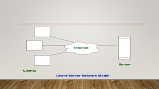
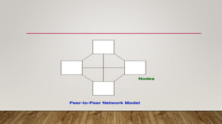
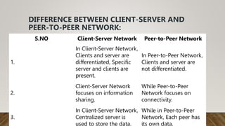
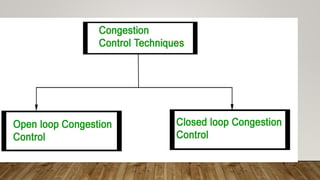
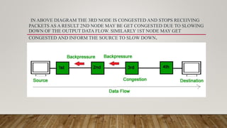
SlideShare a Scribd company logo
CLIENT SERVER
NETWORK AND PEER TO
PEER
NETWORK
CLIENT-SERVER NETWORK: THIS MODEL ARE BROADLY USED NETWORK MODEL. IN CLIENT-SERVER NETWORK, CLIENTS
AND SERVER ARE DIFFERENTIATED, SPECIFIC SERVER AND CLIENTS ARE PRESENT. IN CLIENT-SERVER NETWORK,
CENTRALIZED SERVER IS USED TO STORE THE DATA BECAUSE ITS MANAGEMENT IS CENTRALIZED. IN CLIENT-SERVER
NETWORK, SERVER RESPOND THE SERVICES WHICH IS REQUEST BY CLIENT.
PEER-TO-PEER NETWORK:
• This model does not differentiate the clients and the servers, In this each and every node is itself client and server.
In Peer-to-Peer Network, Each and every node can do both request and respond for the services.
• Peer-to-peer networks are often created by collections of 12 or fewer machines. All of these computers use unique
security to keep their data, but they also share data with every other node.
• In peer-to-peer networks, the nodes both consume and produce resources. Therefore, as the number of nodes
grows, so does the peer-to-peer network’s capability for resource sharing. This is distinct from client-server networks
where an increase in nodes causes the server to become overloaded.
• It is challenging to give nodes in peer-to-peer networks proper security because they function as both clients and
servers. A denial of service attack may result from this.
• The majority of contemporary operating systems, including Windows and Mac OS, come with software to implement
peer
DIFFERENCE BETWEEN CLIENT-SERVER AND
PEER-TO-PEER NETWORK:
S.NO Client-Server Network Peer-to-Peer Network
1.
In Client-Server Network,
Clients and server are
differentiated, Specific
server and clients are
present.
In Peer-to-Peer Network,
Clients and server are
not differentiated.
2.
Client-Server Network
focuses on information
sharing.
While Peer-to-Peer
Network focuses on
connectivity.
3.
In Client-Server Network,
Centralized server is
used to store the data.
While in Peer-to-Peer
Network, Each peer has
its own data.
1.4 OSI MODEL
- RESPONSIBILITIES OF EACH LAYER
• OSI stands for Open Systems Interconnection. It has been developed by ISO –
‘International Organization for Standardization‘, in the year 1984. It is a 7-layer
architecture with each layer having specific functionality to perform. All these 7
layers work collaboratively to transmit the data from one person to another
across the globe.
•
• Layers of OSI Model
1. Physical Layer
2. Data Link Layer
3. Network Layer
4. Transport Layer
5. Session Layer
6. Presentation Layer
7. Application Layer
LAYER 1- PHYSICAL LAYER
• The lowest layer of the OSI reference model is the physical layer. It is responsible for the
actual physical connection between the devices. The physical layer contains information
in the form of bits. It is responsible for transmitting individual bits from one node to the
next. When receiving data, this layer will get the signal received and convert it into 0s and
1s and send them to the Data Link layer, which will put the frame back together.
• The Functions of the Physical Layer
• Bit synchronization: The physical layer provides the synchronization of the bits by providing a
clock. This clock controls both sender and receiver thus providing synchronization at the bit
level.
• Bit rate control: The Physical layer also defines the transmission rate i.e. the number of bits sent
per second.
• Physical topologies: Physical layer specifies how the different, devices/nodes are arranged in a
network i.e. bus, star, or mesh topology.
• Transmission mode: Physical layer also defines how the data flows between the two connected
devices. The various transmission modes possible are Simplex, half-duplex and full-duplex.
LAYER 2- DATA LINK LAYER (DLL)
• The data link layer is responsible for the node-to-node delivery of the message. The main function of this layer is to make sure data transfer
is error-free from one node to another, over the physical layer. When a packet arrives in a network, it is the responsibility of the DLL to
transmit it to the Host using its MAC address.
The Data Link Layer is divided into two sublayers:
1. Logical Link Control (LLC)
2. Media Access Control (MAC)
• The packet received from the Network layer is further divided into frames depending on the frame size of the NIC(Network Interface Card).
DLL also encapsulates Sender and Receiver’s MAC address in the header.
• The Receiver’s MAC address is obtained by placing an ARP(Address Resolution Protocol) request onto the wire asking “Who has that IP
address?” and the destination host will reply with its MAC address.
• The Functions of the Data Link Layer
• Framing: Framing is a function of the data link layer. It provides a way for a sender to transmit a set of bits that are meaningful to the
receiver. This can be accomplished by attaching special bit patterns to the beginning and end of the frame.
• Physical addressing: After creating frames, the Data link layer adds physical addresses (MAC addresses) of the sender and/or receiver in the
header of each frame.
• Error control: The data link layer provides the mechanism of error control in which it detects and retransmits damaged or lost frames.
• Flow Control: The data rate must be constant on both sides else the data may get corrupted thus, flow control coordinates the amount of
data that can be sent before receiving an acknowledgment.
• Access control: When a single communication channel is shared by multiple devices, the MAC sub-layer of the data link layer helps to
determine which device has control over the channel at a given time.
LAYER 3- NETWORK LAYER
• The network layer works for the transmission of data from one host to the other located in
different networks. It also takes care of packet routing i.e. selection of the shortest path to
transmit the packet, from the number of routes available. The sender & receiver’s IP
addresses are placed in the header by the network layer.
• The Functions of the Network Layer
• Routing: The network layer protocols determine which route is suitable from source to
destination. This function of the network layer is known as routing.
• Logical Addressing: To identify each device on Internetwork uniquely, the network layer
defines an addressing scheme. The sender & receiver’s IP addresses are placed in the
header by the network layer. Such an address distinguishes each device uniquely and
universally.
LAYER 4- TRANSPORT LAYER
• The transport layer provides services to the application layer and takes services from the network
layer. The data in the transport layer is referred to as Segments. It is responsible for the End to End
Delivery of the complete message. The transport layer also provides the acknowledgment of the
successful data transmission and re-transmits the data if an error is found.
• At the sender’s side: The transport layer receives the formatted data from the upper layers,
performs Segmentation, and also implements Flow & Error control to ensure proper data
transmission. It also adds Source and Destination port numbers in its header and forwards the
segmented data to the Network Layer.
• Note: The sender needs to know the port number associated with the receiver’s application.
• Generally, this destination port number is configured, either by default or manually. For example,
when a web application requests a web server, it typically uses port number 80, because this is the
default port assigned to web applications. Many applications have default ports assigned.
• At the receiver’s side: Transport Layer reads the port number from its header and forwards the
Data which it has received to the respective application. It also performs sequencing and
reassembling of the segmented data.
LAYER 5- SESSION LAYER
• This layer is responsible for the establishment of connection, maintenance of sessions, and
authentication, and also ensures security.
• The Functions of the Session Layer
• Session establishment, maintenance, and termination: The layer allows the two
processes to establish, use and terminate a connection.
• Synchronization: This layer allows a process to add checkpoints that are considered
synchronization points in the data. These synchronization points help to identify the error
so that the data is re-synchronized properly, and ends of the messages are not cut
prematurely and data loss is avoided.
• Dialog Controller: The session layer allows two systems to start communication with each
other in half-duplex or full-duplex.
LAYER 6- PRESENTATION LAYER
• The presentation layer is also called the Translation layer. The data from the application
layer is extracted here and manipulated as per the required format to transmit over the
network.
• The Functions of the Presentation Layer are
• Translation: For example, ASCII to EBCDIC.
• Encryption/ Decryption: Data encryption translates the data into another form or code.
The encrypted data is known as the ciphertext and the decrypted data is known as plain
text. A key value is used for encrypting as well as decrypting data.
• Compression: Reduces the number of bits that need to be transmitted on the network.
LAYER 7- APPLICATION LAYER
• At the very top of the OSI Reference Model stack of layers, we find the Application layer which is
implemented by the network applications. These applications produce the data, which has to be
transferred over the network. This layer also serves as a window for the application services to access the
network and for displaying the received information to the user.
• Example: Application – Browsers, Skype Messenger, etc.
• Note: 1. The application Layer is also called Desktop Layer.
• 2. Device or Protocol Use : SMTP
• The Functions of the Application Layer are
• Network Virtual Terminal: It allows a user to log on to a remote host.
• FTAM- File transfer access and management : This application allows a user to
access file in a remote host, retrieve files in remote host and manage or
control files from a remote computer.
• Mail Services : Provide email service.
• Directory Services : This application provides distributed database sources
and access for global information about various objects and services.
CONGESTION
NETWORK PERFORMANCE
• Network Congestion occurs when the traffic flowing through a network exceeds its maximum capacity. In most
cases, congestion is a temporary issue with the network caused due to a sudden upsurge of traffic, however, sometimes, a
network is continually congested, indicating a deeper problem. End-users perceive network congestion as Network Slowdown
or a very large delay in processing requests.
• Network congestion is also a contributing factor in the following underlying issues:
• High Latency –
In a congested network, the time taken by a packet to reach its destination increases significantly, hence a higher latency rate
is observed.
• Connection timeouts –
Ideally, the service should wait for the arrival of packets but in several cases, the connection terminates due to timeout.
• Packet loss –
Many packets cannot reach their destination if the network is congested, and will be dropped eventually due to timeout.
• Causes of network congestion :
1. Excessive bandwidth consumption –
Certain users or devices on the network may occasionally utilize more bandwidth than the average user or device. This
can put a strain on the network and its routing equipment (routers, switches, and cables), causing network congestion.
2. Poor subnet management –
For better resource management, a big network is divided into subnets. However, network congestion could arise if the
subnets are not scaled according to usage patterns and resource requirements.
3. Broadcast Storms –
A broadcast storm occurs when there is a sudden upsurge in the number of requests to a network. As a result, a network
may be unable to handle all of the requests at the same time.
4. Multicasting –
Multicasting occurs when a network allows multiple computers to communicate with each other at the same time. In
multicasting, a collision can occur when two packets are sent at the same time. Such frequent collisions may cause a
network to be congested.
5. Border Gateway Protocol –
All traffic is routed by BGP via the shortest possible path. However, while routing a packet, it doesn’t consider the amount
of traffic present in the route. In such scenarios, there is a possibility all the packets are being routed via the same route
which may lead to network congestion.
6. Too many devices –
CONGESTION CONTROL
• Congestion control refers to the techniques used to control or prevent
congestion. Congestion control techniques can be broadly classified into two
categories:
OPEN LOOP CONGESTION CONTROL
OPEN LOOP CONGESTION CONTROL POLICIES ARE APPLIED TO PREVENT CONGESTION BEFORE IT HAPPENS. THE
CONGESTION CONTROL IS HANDLED EITHER BY THE SOURCE OR THE DESTINATION.
• Policies adopted by open loop congestion control –
1.Retransmission Policy :
It is the policy in which retransmission of the packets are taken care of. If the sender feels that
a sent packet is lost or corrupted, the packet needs to be retransmitted. This transmission may
increase the congestion in the network.
To prevent congestion, retransmission timers must be designed to prevent congestion and
also able to optimize efficiency.
2. Window Policy :
The type of window at the sender’s side may also affect the congestion. Several packets in the Go-back-n window
are re-sent, although some packets may be received successfully at the receiver side. This duplication may increase
the congestion in the network and make it worse.
Therefore, Selective repeat window should be adopted as it sends the specific packet that may have been lost.
3 Discarding Policy :
A good discarding policy adopted by the routers is that the routers may prevent congestion and at the same time
partially discard the corrupted or less sensitive packages and also be able to maintain the quality of a message.
In case of audio file transmission, routers can discard less sensitive packets to prevent congestion and also
maintain the quality of the audio file.
4 Acknowledgment Policy :
Since acknowledgements are also the part of the load in the network, the acknowledgment policy imposed by the
receiver may also affect congestion. Several approaches can be used to prevent congestion related to
acknowledgment.
The receiver should send acknowledgement for N packets rather than sending acknowledgement for a single
packet. The receiver should send an acknowledgment only if it has to send a packet or a timer expires.
• 5 Admission Policy :
In admission policy a mechanism should be used to prevent congestion. Switches
in a flow should first check the resource requirement of a network flow before
transmitting it further. If there is a chance of a congestion or there is a congestion
in the network, router should deny establishing a virtual network connection to
prevent further congestion.
CLOSED LOOP CONGESTION CONTROL
• Closed loop congestion control techniques are used to treat or alleviate
congestion after it happens. Several techniques are used by different protocols;
some of them are:
• 1. Backpressure :
Backpressure is a technique in which a congested node stops receiving packets
from upstream node. This may cause the upstream node or nodes to become
congested and reject receiving data from above nodes. Backpressure is a node-
to-node congestion control technique that propagate in the opposite direction of
data flow. The backpressure technique can be applied only to virtual circuit where
each node has information of its above upstream node.
IN ABOVE DIAGRAM THE 3RD NODE IS CONGESTED AND STOPS RECEIVING
PACKETS AS A RESULT 2ND NODE MAY BE GET CONGESTED DUE TO SLOWING
DOWN OF THE OUTPUT DATA FLOW. SIMILARLY 1ST NODE MAY GET
CONGESTED AND INFORM THE SOURCE TO SLOW DOWN.
Client Server Network and Peer to Peer.pptx

More Related Content

Similar to Client Server Network and Peer to Peer.pptx

Viloria osi layer4-7
Viloria osi layer4-7Viloria osi layer4-7
Viloria osi layer4-7
Jhoniel Viloria
 
OSI MODEL
OSI MODEL OSI MODEL
OSI MODEL
Soumo Dhali
 
Network internet
Network internetNetwork internet
Network internetKumar
 
Networks internet
Networks internetNetworks internet
Networks internetKumar
 
tcpiposi.pptx
tcpiposi.pptxtcpiposi.pptx
tcpiposi.pptx
JustinMathew73
 
Concept of OSI Model_KSMS_BCA_4th_6th_Sem_Priyanka Bhattacharya_20th March 2020
Concept of OSI Model_KSMS_BCA_4th_6th_Sem_Priyanka Bhattacharya_20th March  2020Concept of OSI Model_KSMS_BCA_4th_6th_Sem_Priyanka Bhattacharya_20th March  2020
Concept of OSI Model_KSMS_BCA_4th_6th_Sem_Priyanka Bhattacharya_20th March 2020
PriyankaBhattacharya28
 
OSI layer (Network)
OSI layer (Network)OSI layer (Network)
OSI layer (Network)
swethaRajendran1
 
Dc2 t1
Dc2 t1Dc2 t1
Presentation of computer network on data link layer
Presentation of computer network on data link layerPresentation of computer network on data link layer
Presentation of computer network on data link layer
sumit gyawali
 
ch5-osi.pdf
ch5-osi.pdfch5-osi.pdf
ch5-osi.pdf
ssuserc8e1481
 
Osi
OsiOsi
BAPANKAR15800121011 SOFT.pptx
BAPANKAR15800121011 SOFT.pptxBAPANKAR15800121011 SOFT.pptx
BAPANKAR15800121011 SOFT.pptx
BapanKar2
 
MVA slides lesson 2
MVA slides lesson 2MVA slides lesson 2
Basics of Ethernet
Basics of Ethernet Basics of Ethernet
Basics of Ethernet
Pushpa Yakkala
 
Sargation university's open system interconnection
Sargation university's open system interconnectionSargation university's open system interconnection
Sargation university's open system interconnection
KingPinYT
 
unit1 network model osi and tcpip.pptx
unit1  network model osi and tcpip.pptxunit1  network model osi and tcpip.pptx
unit1 network model osi and tcpip.pptx
183JAIDEEP
 
how does the OSI Model relate to the seven domains of an IT infrastr.pdf
how does the OSI Model relate to the seven domains of an IT infrastr.pdfhow does the OSI Model relate to the seven domains of an IT infrastr.pdf
how does the OSI Model relate to the seven domains of an IT infrastr.pdf
mohammedfootwear
 
OSI &TCP/IP Model
OSI &TCP/IP ModelOSI &TCP/IP Model
OSI &TCP/IP Model
Shamima Akther
 
Osi layer model
Osi layer modelOsi layer model
Osi layer model
AanchalJain72
 
The OSI model
 The OSI model The OSI model
The OSI model
ShofiqulIslam38
 

Similar to Client Server Network and Peer to Peer.pptx (20)

Viloria osi layer4-7
Viloria osi layer4-7Viloria osi layer4-7
Viloria osi layer4-7
 
OSI MODEL
OSI MODEL OSI MODEL
OSI MODEL
 
Network internet
Network internetNetwork internet
Network internet
 
Networks internet
Networks internetNetworks internet
Networks internet
 
tcpiposi.pptx
tcpiposi.pptxtcpiposi.pptx
tcpiposi.pptx
 
Concept of OSI Model_KSMS_BCA_4th_6th_Sem_Priyanka Bhattacharya_20th March 2020
Concept of OSI Model_KSMS_BCA_4th_6th_Sem_Priyanka Bhattacharya_20th March  2020Concept of OSI Model_KSMS_BCA_4th_6th_Sem_Priyanka Bhattacharya_20th March  2020
Concept of OSI Model_KSMS_BCA_4th_6th_Sem_Priyanka Bhattacharya_20th March 2020
 
OSI layer (Network)
OSI layer (Network)OSI layer (Network)
OSI layer (Network)
 
Dc2 t1
Dc2 t1Dc2 t1
Dc2 t1
 
Presentation of computer network on data link layer
Presentation of computer network on data link layerPresentation of computer network on data link layer
Presentation of computer network on data link layer
 
ch5-osi.pdf
ch5-osi.pdfch5-osi.pdf
ch5-osi.pdf
 
Osi
OsiOsi
Osi
 
BAPANKAR15800121011 SOFT.pptx
BAPANKAR15800121011 SOFT.pptxBAPANKAR15800121011 SOFT.pptx
BAPANKAR15800121011 SOFT.pptx
 
MVA slides lesson 2
MVA slides lesson 2MVA slides lesson 2
MVA slides lesson 2
 
Basics of Ethernet
Basics of Ethernet Basics of Ethernet
Basics of Ethernet
 
Sargation university's open system interconnection
Sargation university's open system interconnectionSargation university's open system interconnection
Sargation university's open system interconnection
 
unit1 network model osi and tcpip.pptx
unit1  network model osi and tcpip.pptxunit1  network model osi and tcpip.pptx
unit1 network model osi and tcpip.pptx
 
how does the OSI Model relate to the seven domains of an IT infrastr.pdf
how does the OSI Model relate to the seven domains of an IT infrastr.pdfhow does the OSI Model relate to the seven domains of an IT infrastr.pdf
how does the OSI Model relate to the seven domains of an IT infrastr.pdf
 
OSI &TCP/IP Model
OSI &TCP/IP ModelOSI &TCP/IP Model
OSI &TCP/IP Model
 
Osi layer model
Osi layer modelOsi layer model
Osi layer model
 
The OSI model
 The OSI model The OSI model
The OSI model
 

Recently uploaded

Cosmetic shop management system project report.pdf
Cosmetic shop management system project report.pdfCosmetic shop management system project report.pdf
Cosmetic shop management system project report.pdf
Kamal Acharya
 
H.Seo, ICLR 2024, MLILAB, KAIST AI.pdf
H.Seo,  ICLR 2024, MLILAB,  KAIST AI.pdfH.Seo,  ICLR 2024, MLILAB,  KAIST AI.pdf
H.Seo, ICLR 2024, MLILAB, KAIST AI.pdf
MLILAB
 
Halogenation process of chemical process industries
Halogenation process of chemical process industriesHalogenation process of chemical process industries
Halogenation process of chemical process industries
MuhammadTufail242431
 
Standard Reomte Control Interface - Neometrix
Standard Reomte Control Interface - NeometrixStandard Reomte Control Interface - Neometrix
Standard Reomte Control Interface - Neometrix
Neometrix_Engineering_Pvt_Ltd
 
在线办理(ANU毕业证书)澳洲国立大学毕业证录取通知书一模一样
在线办理(ANU毕业证书)澳洲国立大学毕业证录取通知书一模一样在线办理(ANU毕业证书)澳洲国立大学毕业证录取通知书一模一样
在线办理(ANU毕业证书)澳洲国立大学毕业证录取通知书一模一样
obonagu
 
Industrial Training at Shahjalal Fertilizer Company Limited (SFCL)
Industrial Training at Shahjalal Fertilizer Company Limited (SFCL)Industrial Training at Shahjalal Fertilizer Company Limited (SFCL)
Industrial Training at Shahjalal Fertilizer Company Limited (SFCL)
MdTanvirMahtab2
 
WATER CRISIS and its solutions-pptx 1234
WATER CRISIS and its solutions-pptx 1234WATER CRISIS and its solutions-pptx 1234
WATER CRISIS and its solutions-pptx 1234
AafreenAbuthahir2
 
The Benefits and Techniques of Trenchless Pipe Repair.pdf
The Benefits and Techniques of Trenchless Pipe Repair.pdfThe Benefits and Techniques of Trenchless Pipe Repair.pdf
The Benefits and Techniques of Trenchless Pipe Repair.pdf
Pipe Restoration Solutions
 
Courier management system project report.pdf
Courier management system project report.pdfCourier management system project report.pdf
Courier management system project report.pdf
Kamal Acharya
 
LIGA(E)11111111111111111111111111111111111111111.ppt
LIGA(E)11111111111111111111111111111111111111111.pptLIGA(E)11111111111111111111111111111111111111111.ppt
LIGA(E)11111111111111111111111111111111111111111.ppt
ssuser9bd3ba
 
Sachpazis:Terzaghi Bearing Capacity Estimation in simple terms with Calculati...
Sachpazis:Terzaghi Bearing Capacity Estimation in simple terms with Calculati...Sachpazis:Terzaghi Bearing Capacity Estimation in simple terms with Calculati...
Sachpazis:Terzaghi Bearing Capacity Estimation in simple terms with Calculati...
Dr.Costas Sachpazis
 
Final project report on grocery store management system..pdf
Final project report on grocery store management system..pdfFinal project report on grocery store management system..pdf
Final project report on grocery store management system..pdf
Kamal Acharya
 
weather web application report.pdf
weather web application report.pdfweather web application report.pdf
weather web application report.pdf
Pratik Pawar
 
MCQ Soil mechanics questions (Soil shear strength).pdf
MCQ Soil mechanics questions (Soil shear strength).pdfMCQ Soil mechanics questions (Soil shear strength).pdf
MCQ Soil mechanics questions (Soil shear strength).pdf
Osamah Alsalih
 
Pile Foundation by Venkatesh Taduvai (Sub Geotechnical Engineering II)-conver...
Pile Foundation by Venkatesh Taduvai (Sub Geotechnical Engineering II)-conver...Pile Foundation by Venkatesh Taduvai (Sub Geotechnical Engineering II)-conver...
Pile Foundation by Venkatesh Taduvai (Sub Geotechnical Engineering II)-conver...
AJAYKUMARPUND1
 
DESIGN A COTTON SEED SEPARATION MACHINE.docx
DESIGN A COTTON SEED SEPARATION MACHINE.docxDESIGN A COTTON SEED SEPARATION MACHINE.docx
DESIGN A COTTON SEED SEPARATION MACHINE.docx
FluxPrime1
 
Design and Analysis of Algorithms-DP,Backtracking,Graphs,B&B
Design and Analysis of Algorithms-DP,Backtracking,Graphs,B&BDesign and Analysis of Algorithms-DP,Backtracking,Graphs,B&B
Design and Analysis of Algorithms-DP,Backtracking,Graphs,B&B
Sreedhar Chowdam
 
Immunizing Image Classifiers Against Localized Adversary Attacks
Immunizing Image Classifiers Against Localized Adversary AttacksImmunizing Image Classifiers Against Localized Adversary Attacks
Immunizing Image Classifiers Against Localized Adversary Attacks
gerogepatton
 
HYDROPOWER - Hydroelectric power generation
HYDROPOWER - Hydroelectric power generationHYDROPOWER - Hydroelectric power generation
HYDROPOWER - Hydroelectric power generation
Robbie Edward Sayers
 
TECHNICAL TRAINING MANUAL GENERAL FAMILIARIZATION COURSE
TECHNICAL TRAINING MANUAL   GENERAL FAMILIARIZATION COURSETECHNICAL TRAINING MANUAL   GENERAL FAMILIARIZATION COURSE
TECHNICAL TRAINING MANUAL GENERAL FAMILIARIZATION COURSE
DuvanRamosGarzon1
 

Recently uploaded (20)

Cosmetic shop management system project report.pdf
Cosmetic shop management system project report.pdfCosmetic shop management system project report.pdf
Cosmetic shop management system project report.pdf
 
H.Seo, ICLR 2024, MLILAB, KAIST AI.pdf
H.Seo,  ICLR 2024, MLILAB,  KAIST AI.pdfH.Seo,  ICLR 2024, MLILAB,  KAIST AI.pdf
H.Seo, ICLR 2024, MLILAB, KAIST AI.pdf
 
Halogenation process of chemical process industries
Halogenation process of chemical process industriesHalogenation process of chemical process industries
Halogenation process of chemical process industries
 
Standard Reomte Control Interface - Neometrix
Standard Reomte Control Interface - NeometrixStandard Reomte Control Interface - Neometrix
Standard Reomte Control Interface - Neometrix
 
在线办理(ANU毕业证书)澳洲国立大学毕业证录取通知书一模一样
在线办理(ANU毕业证书)澳洲国立大学毕业证录取通知书一模一样在线办理(ANU毕业证书)澳洲国立大学毕业证录取通知书一模一样
在线办理(ANU毕业证书)澳洲国立大学毕业证录取通知书一模一样
 
Industrial Training at Shahjalal Fertilizer Company Limited (SFCL)
Industrial Training at Shahjalal Fertilizer Company Limited (SFCL)Industrial Training at Shahjalal Fertilizer Company Limited (SFCL)
Industrial Training at Shahjalal Fertilizer Company Limited (SFCL)
 
WATER CRISIS and its solutions-pptx 1234
WATER CRISIS and its solutions-pptx 1234WATER CRISIS and its solutions-pptx 1234
WATER CRISIS and its solutions-pptx 1234
 
The Benefits and Techniques of Trenchless Pipe Repair.pdf
The Benefits and Techniques of Trenchless Pipe Repair.pdfThe Benefits and Techniques of Trenchless Pipe Repair.pdf
The Benefits and Techniques of Trenchless Pipe Repair.pdf
 
Courier management system project report.pdf
Courier management system project report.pdfCourier management system project report.pdf
Courier management system project report.pdf
 
LIGA(E)11111111111111111111111111111111111111111.ppt
LIGA(E)11111111111111111111111111111111111111111.pptLIGA(E)11111111111111111111111111111111111111111.ppt
LIGA(E)11111111111111111111111111111111111111111.ppt
 
Sachpazis:Terzaghi Bearing Capacity Estimation in simple terms with Calculati...
Sachpazis:Terzaghi Bearing Capacity Estimation in simple terms with Calculati...Sachpazis:Terzaghi Bearing Capacity Estimation in simple terms with Calculati...
Sachpazis:Terzaghi Bearing Capacity Estimation in simple terms with Calculati...
 
Final project report on grocery store management system..pdf
Final project report on grocery store management system..pdfFinal project report on grocery store management system..pdf
Final project report on grocery store management system..pdf
 
weather web application report.pdf
weather web application report.pdfweather web application report.pdf
weather web application report.pdf
 
MCQ Soil mechanics questions (Soil shear strength).pdf
MCQ Soil mechanics questions (Soil shear strength).pdfMCQ Soil mechanics questions (Soil shear strength).pdf
MCQ Soil mechanics questions (Soil shear strength).pdf
 
Pile Foundation by Venkatesh Taduvai (Sub Geotechnical Engineering II)-conver...
Pile Foundation by Venkatesh Taduvai (Sub Geotechnical Engineering II)-conver...Pile Foundation by Venkatesh Taduvai (Sub Geotechnical Engineering II)-conver...
Pile Foundation by Venkatesh Taduvai (Sub Geotechnical Engineering II)-conver...
 
DESIGN A COTTON SEED SEPARATION MACHINE.docx
DESIGN A COTTON SEED SEPARATION MACHINE.docxDESIGN A COTTON SEED SEPARATION MACHINE.docx
DESIGN A COTTON SEED SEPARATION MACHINE.docx
 
Design and Analysis of Algorithms-DP,Backtracking,Graphs,B&B
Design and Analysis of Algorithms-DP,Backtracking,Graphs,B&BDesign and Analysis of Algorithms-DP,Backtracking,Graphs,B&B
Design and Analysis of Algorithms-DP,Backtracking,Graphs,B&B
 
Immunizing Image Classifiers Against Localized Adversary Attacks
Immunizing Image Classifiers Against Localized Adversary AttacksImmunizing Image Classifiers Against Localized Adversary Attacks
Immunizing Image Classifiers Against Localized Adversary Attacks
 
HYDROPOWER - Hydroelectric power generation
HYDROPOWER - Hydroelectric power generationHYDROPOWER - Hydroelectric power generation
HYDROPOWER - Hydroelectric power generation
 
TECHNICAL TRAINING MANUAL GENERAL FAMILIARIZATION COURSE
TECHNICAL TRAINING MANUAL   GENERAL FAMILIARIZATION COURSETECHNICAL TRAINING MANUAL   GENERAL FAMILIARIZATION COURSE
TECHNICAL TRAINING MANUAL GENERAL FAMILIARIZATION COURSE
 

Client Server Network and Peer to Peer.pptx

  • 1. CLIENT SERVER NETWORK AND PEER TO PEER NETWORK CLIENT-SERVER NETWORK: THIS MODEL ARE BROADLY USED NETWORK MODEL. IN CLIENT-SERVER NETWORK, CLIENTS AND SERVER ARE DIFFERENTIATED, SPECIFIC SERVER AND CLIENTS ARE PRESENT. IN CLIENT-SERVER NETWORK, CENTRALIZED SERVER IS USED TO STORE THE DATA BECAUSE ITS MANAGEMENT IS CENTRALIZED. IN CLIENT-SERVER NETWORK, SERVER RESPOND THE SERVICES WHICH IS REQUEST BY CLIENT.
  • 2.
  • 3. PEER-TO-PEER NETWORK: • This model does not differentiate the clients and the servers, In this each and every node is itself client and server. In Peer-to-Peer Network, Each and every node can do both request and respond for the services. • Peer-to-peer networks are often created by collections of 12 or fewer machines. All of these computers use unique security to keep their data, but they also share data with every other node. • In peer-to-peer networks, the nodes both consume and produce resources. Therefore, as the number of nodes grows, so does the peer-to-peer network’s capability for resource sharing. This is distinct from client-server networks where an increase in nodes causes the server to become overloaded. • It is challenging to give nodes in peer-to-peer networks proper security because they function as both clients and servers. A denial of service attack may result from this. • The majority of contemporary operating systems, including Windows and Mac OS, come with software to implement peer
  • 4.
  • 5. DIFFERENCE BETWEEN CLIENT-SERVER AND PEER-TO-PEER NETWORK: S.NO Client-Server Network Peer-to-Peer Network 1. In Client-Server Network, Clients and server are differentiated, Specific server and clients are present. In Peer-to-Peer Network, Clients and server are not differentiated. 2. Client-Server Network focuses on information sharing. While Peer-to-Peer Network focuses on connectivity. 3. In Client-Server Network, Centralized server is used to store the data. While in Peer-to-Peer Network, Each peer has its own data.
  • 6. 1.4 OSI MODEL - RESPONSIBILITIES OF EACH LAYER • OSI stands for Open Systems Interconnection. It has been developed by ISO – ‘International Organization for Standardization‘, in the year 1984. It is a 7-layer architecture with each layer having specific functionality to perform. All these 7 layers work collaboratively to transmit the data from one person to another across the globe.
  • 7.
  • 8. • • Layers of OSI Model 1. Physical Layer 2. Data Link Layer 3. Network Layer 4. Transport Layer 5. Session Layer 6. Presentation Layer 7. Application Layer
  • 9. LAYER 1- PHYSICAL LAYER • The lowest layer of the OSI reference model is the physical layer. It is responsible for the actual physical connection between the devices. The physical layer contains information in the form of bits. It is responsible for transmitting individual bits from one node to the next. When receiving data, this layer will get the signal received and convert it into 0s and 1s and send them to the Data Link layer, which will put the frame back together.
  • 10. • The Functions of the Physical Layer • Bit synchronization: The physical layer provides the synchronization of the bits by providing a clock. This clock controls both sender and receiver thus providing synchronization at the bit level. • Bit rate control: The Physical layer also defines the transmission rate i.e. the number of bits sent per second. • Physical topologies: Physical layer specifies how the different, devices/nodes are arranged in a network i.e. bus, star, or mesh topology. • Transmission mode: Physical layer also defines how the data flows between the two connected devices. The various transmission modes possible are Simplex, half-duplex and full-duplex.
  • 11. LAYER 2- DATA LINK LAYER (DLL) • The data link layer is responsible for the node-to-node delivery of the message. The main function of this layer is to make sure data transfer is error-free from one node to another, over the physical layer. When a packet arrives in a network, it is the responsibility of the DLL to transmit it to the Host using its MAC address. The Data Link Layer is divided into two sublayers: 1. Logical Link Control (LLC) 2. Media Access Control (MAC) • The packet received from the Network layer is further divided into frames depending on the frame size of the NIC(Network Interface Card). DLL also encapsulates Sender and Receiver’s MAC address in the header. • The Receiver’s MAC address is obtained by placing an ARP(Address Resolution Protocol) request onto the wire asking “Who has that IP address?” and the destination host will reply with its MAC address. • The Functions of the Data Link Layer • Framing: Framing is a function of the data link layer. It provides a way for a sender to transmit a set of bits that are meaningful to the receiver. This can be accomplished by attaching special bit patterns to the beginning and end of the frame. • Physical addressing: After creating frames, the Data link layer adds physical addresses (MAC addresses) of the sender and/or receiver in the header of each frame. • Error control: The data link layer provides the mechanism of error control in which it detects and retransmits damaged or lost frames. • Flow Control: The data rate must be constant on both sides else the data may get corrupted thus, flow control coordinates the amount of data that can be sent before receiving an acknowledgment. • Access control: When a single communication channel is shared by multiple devices, the MAC sub-layer of the data link layer helps to determine which device has control over the channel at a given time.
  • 12. LAYER 3- NETWORK LAYER • The network layer works for the transmission of data from one host to the other located in different networks. It also takes care of packet routing i.e. selection of the shortest path to transmit the packet, from the number of routes available. The sender & receiver’s IP addresses are placed in the header by the network layer. • The Functions of the Network Layer • Routing: The network layer protocols determine which route is suitable from source to destination. This function of the network layer is known as routing. • Logical Addressing: To identify each device on Internetwork uniquely, the network layer defines an addressing scheme. The sender & receiver’s IP addresses are placed in the header by the network layer. Such an address distinguishes each device uniquely and universally.
  • 13. LAYER 4- TRANSPORT LAYER • The transport layer provides services to the application layer and takes services from the network layer. The data in the transport layer is referred to as Segments. It is responsible for the End to End Delivery of the complete message. The transport layer also provides the acknowledgment of the successful data transmission and re-transmits the data if an error is found. • At the sender’s side: The transport layer receives the formatted data from the upper layers, performs Segmentation, and also implements Flow & Error control to ensure proper data transmission. It also adds Source and Destination port numbers in its header and forwards the segmented data to the Network Layer. • Note: The sender needs to know the port number associated with the receiver’s application. • Generally, this destination port number is configured, either by default or manually. For example, when a web application requests a web server, it typically uses port number 80, because this is the default port assigned to web applications. Many applications have default ports assigned. • At the receiver’s side: Transport Layer reads the port number from its header and forwards the Data which it has received to the respective application. It also performs sequencing and reassembling of the segmented data.
  • 14. LAYER 5- SESSION LAYER • This layer is responsible for the establishment of connection, maintenance of sessions, and authentication, and also ensures security. • The Functions of the Session Layer • Session establishment, maintenance, and termination: The layer allows the two processes to establish, use and terminate a connection. • Synchronization: This layer allows a process to add checkpoints that are considered synchronization points in the data. These synchronization points help to identify the error so that the data is re-synchronized properly, and ends of the messages are not cut prematurely and data loss is avoided. • Dialog Controller: The session layer allows two systems to start communication with each other in half-duplex or full-duplex.
  • 15. LAYER 6- PRESENTATION LAYER • The presentation layer is also called the Translation layer. The data from the application layer is extracted here and manipulated as per the required format to transmit over the network. • The Functions of the Presentation Layer are • Translation: For example, ASCII to EBCDIC. • Encryption/ Decryption: Data encryption translates the data into another form or code. The encrypted data is known as the ciphertext and the decrypted data is known as plain text. A key value is used for encrypting as well as decrypting data. • Compression: Reduces the number of bits that need to be transmitted on the network.
  • 16. LAYER 7- APPLICATION LAYER • At the very top of the OSI Reference Model stack of layers, we find the Application layer which is implemented by the network applications. These applications produce the data, which has to be transferred over the network. This layer also serves as a window for the application services to access the network and for displaying the received information to the user. • Example: Application – Browsers, Skype Messenger, etc. • Note: 1. The application Layer is also called Desktop Layer. • 2. Device or Protocol Use : SMTP • The Functions of the Application Layer are • Network Virtual Terminal: It allows a user to log on to a remote host. • FTAM- File transfer access and management : This application allows a user to access file in a remote host, retrieve files in remote host and manage or control files from a remote computer. • Mail Services : Provide email service. • Directory Services : This application provides distributed database sources and access for global information about various objects and services.
  • 17. CONGESTION NETWORK PERFORMANCE • Network Congestion occurs when the traffic flowing through a network exceeds its maximum capacity. In most cases, congestion is a temporary issue with the network caused due to a sudden upsurge of traffic, however, sometimes, a network is continually congested, indicating a deeper problem. End-users perceive network congestion as Network Slowdown or a very large delay in processing requests. • Network congestion is also a contributing factor in the following underlying issues: • High Latency – In a congested network, the time taken by a packet to reach its destination increases significantly, hence a higher latency rate is observed. • Connection timeouts – Ideally, the service should wait for the arrival of packets but in several cases, the connection terminates due to timeout. • Packet loss – Many packets cannot reach their destination if the network is congested, and will be dropped eventually due to timeout.
  • 18. • Causes of network congestion : 1. Excessive bandwidth consumption – Certain users or devices on the network may occasionally utilize more bandwidth than the average user or device. This can put a strain on the network and its routing equipment (routers, switches, and cables), causing network congestion. 2. Poor subnet management – For better resource management, a big network is divided into subnets. However, network congestion could arise if the subnets are not scaled according to usage patterns and resource requirements. 3. Broadcast Storms – A broadcast storm occurs when there is a sudden upsurge in the number of requests to a network. As a result, a network may be unable to handle all of the requests at the same time. 4. Multicasting – Multicasting occurs when a network allows multiple computers to communicate with each other at the same time. In multicasting, a collision can occur when two packets are sent at the same time. Such frequent collisions may cause a network to be congested. 5. Border Gateway Protocol – All traffic is routed by BGP via the shortest possible path. However, while routing a packet, it doesn’t consider the amount of traffic present in the route. In such scenarios, there is a possibility all the packets are being routed via the same route which may lead to network congestion. 6. Too many devices –
  • 19. CONGESTION CONTROL • Congestion control refers to the techniques used to control or prevent congestion. Congestion control techniques can be broadly classified into two categories:
  • 20.
  • 21. OPEN LOOP CONGESTION CONTROL OPEN LOOP CONGESTION CONTROL POLICIES ARE APPLIED TO PREVENT CONGESTION BEFORE IT HAPPENS. THE CONGESTION CONTROL IS HANDLED EITHER BY THE SOURCE OR THE DESTINATION. • Policies adopted by open loop congestion control – 1.Retransmission Policy : It is the policy in which retransmission of the packets are taken care of. If the sender feels that a sent packet is lost or corrupted, the packet needs to be retransmitted. This transmission may increase the congestion in the network. To prevent congestion, retransmission timers must be designed to prevent congestion and also able to optimize efficiency.
  • 22. 2. Window Policy : The type of window at the sender’s side may also affect the congestion. Several packets in the Go-back-n window are re-sent, although some packets may be received successfully at the receiver side. This duplication may increase the congestion in the network and make it worse. Therefore, Selective repeat window should be adopted as it sends the specific packet that may have been lost. 3 Discarding Policy : A good discarding policy adopted by the routers is that the routers may prevent congestion and at the same time partially discard the corrupted or less sensitive packages and also be able to maintain the quality of a message. In case of audio file transmission, routers can discard less sensitive packets to prevent congestion and also maintain the quality of the audio file. 4 Acknowledgment Policy : Since acknowledgements are also the part of the load in the network, the acknowledgment policy imposed by the receiver may also affect congestion. Several approaches can be used to prevent congestion related to acknowledgment. The receiver should send acknowledgement for N packets rather than sending acknowledgement for a single packet. The receiver should send an acknowledgment only if it has to send a packet or a timer expires.
  • 23. • 5 Admission Policy : In admission policy a mechanism should be used to prevent congestion. Switches in a flow should first check the resource requirement of a network flow before transmitting it further. If there is a chance of a congestion or there is a congestion in the network, router should deny establishing a virtual network connection to prevent further congestion.
  • 24. CLOSED LOOP CONGESTION CONTROL • Closed loop congestion control techniques are used to treat or alleviate congestion after it happens. Several techniques are used by different protocols; some of them are:
  • 25. • 1. Backpressure : Backpressure is a technique in which a congested node stops receiving packets from upstream node. This may cause the upstream node or nodes to become congested and reject receiving data from above nodes. Backpressure is a node- to-node congestion control technique that propagate in the opposite direction of data flow. The backpressure technique can be applied only to virtual circuit where each node has information of its above upstream node.
  • 26. IN ABOVE DIAGRAM THE 3RD NODE IS CONGESTED AND STOPS RECEIVING PACKETS AS A RESULT 2ND NODE MAY BE GET CONGESTED DUE TO SLOWING DOWN OF THE OUTPUT DATA FLOW. SIMILARLY 1ST NODE MAY GET CONGESTED AND INFORM THE SOURCE TO SLOW DOWN.