Download to read offline


![Sources
1. Figure 1
ADL3 data logger [Digital image]. (n.d.). Retrieved October 11, 2016, from
http://www.bimmerforums.com/forum/archive/index.php/t-1579010.html
2. Figure 8
ARB Drop Link Force [Digital image]. (n.d.). Retrieved October 11, 2016, from
http://www.pistonheads.com/gassing/topic.asp?t=1131871
3. Figure 5
Damper Travel [Digital image]. (n.d.). Retrieved October 11, 2016, from
http://www.fsae.com/forums/archive/index.php/t-
5776.html?s=2f4ac3793225a1cc9fb6f05198249449
4. Figure 3
Wheel Speed Sensor Mounting [Digital image]. (n.d.). Retrieved October 11, 2016, from
http://www.aa1car.com/library/diagnosing_abs_wheels_speed_sensors.htm
5. Figure 4
Trigger Wheel and Hub [Digital image]. (n.d.). Retrieved October 11, 2016, from
http://www.americanmuscle.com/mustang-frontwheel-hub-bearing-9404.html
6. Figure 6
Load Cell [Digital image]. (n.d.). Retrieved October 11, 2016, from
http://www.raetech.com/Instrumentation/images/Coil-over-Installation-400x533.jpg
7. Figure 7
Load Cell [Digital image]. (n.d.). Retrieved October 11, 2016, from
http://www.interfaceforce.com/index.php?&mod=applications&show=24](https://image.slidesharecdn.com/mste330blackgroupproject1report-170325004018/85/Data-Acquisition-Project-Report-27-320.jpg)

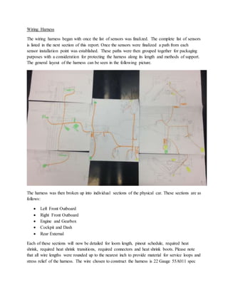
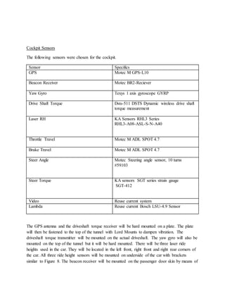
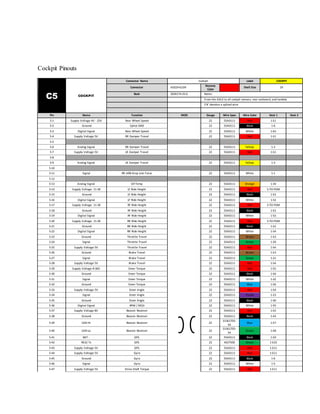
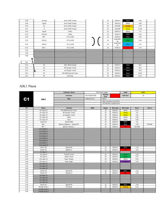
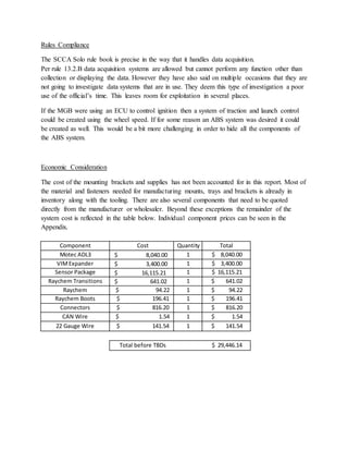
The document summarizes a project to create a mock wiring harness and data acquisition system for an IUPUI Motorsports Engineering MGB GT solo car. Key aspects include: - Selection of Motec ADL3 dash logger and VIM expander to log data from selected sensors via CAN communication. - Development of wiring harness in separate sections for different areas of the car, with heat shrink, boots, and connectors to protect wires. - Selection of sensors for wheel speed, damper travel, spring force, and anti-roll bar drop link force. - Pinouts and connector details for wiring individual sensor sections and routing them back to the data loggers.


![Attack surfaces and attack tress[inform]](https://cdn.slidesharecdn.com/ss_thumbnails/lecture03-260108015941-a4dee53b-thumbnail.jpg?width=640&height=640&fit=bounds)


