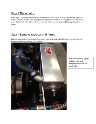
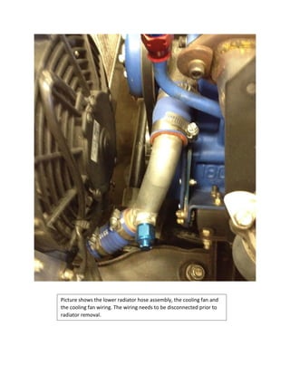
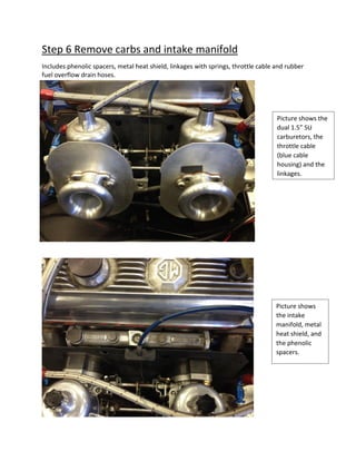
MGB Engine Removal
Procedure
By Joseph Legan
Beginning Notes:
 All work must be done by a minimum of 2 people for safety reasons.
 There is one metric tool needed for one the following procedures.
 There are no power tools needed for any of the following procedures.
 Read ALL directions before any work is begun.
 Adhere to all lab rules at all times.
Step 0 Questions and Torque Values
When in doubt, ask. There are no wrong questions so ask away. When working on the MGB or
any other vehicle use the assigned torque values. The torque values for this car can be found in
the resource area of the class website and in the various service manuals in the lab.
If there is no torques value listed then use the appropriate torque for the fastener size. A chart
of torque by fastener size can be found in the resources area of the class website.
Step 1 Disconnect battery
Battery is located under parcel tray cover immediately behind drivers seat on the passenger side.
Battery terminals require a 10mm metric wrench to remove.
Step 2 Elevate Car on jack stands
Elevate as high as possible. The rear jack stand are to be placed on the rear axle itself as wide as possible
without crushing and brake line. The front jack stands are to be placed on the unibody frame 6 to 8
inches in front of the cross member. Once the weight of the car is on the jack stands test the rigidity of
the stand placement by shaking the car moderately. Adjust the position of the stands if any there is any
doubt to the safety a worker underneath the car.
Step 3 Drain fluids
Drain engine oil, coolant, transmission lube and remove the oil filter. Drain coolant through petcock on
radiator. Remove oil filter after the engine oil has been drained. Place all drained fluids into the correct
waste fluid barrels in the lab and clean any funnels, catch pans and tools used before putting them
away.
Step 4 Remove radiator and hoses
Pay attention to the orientation of the lower hose assembly, label wiring connections for the
fan and the temp sensor on the radiator.
Picture of radiator, upper
radiator hose and
temperature switch for
cooling fan.
Picture shows the lower radiator hose assembly, the cooling fan and
the cooling fan wiring. The wiring needs to be disconnected prior to
radiator removal.
Step 5 Disconnect fuel lines
Disconnect from carbs and tuck away in the drivers side firewall area.
Picture shows the dual fuel
lines coming from the fuel
pressure regulator and the
crankcase ventilation line as
well.
Step 6 Remove carbs and intake manifold
Includes phenolic spacers, metal heat shield, linkages with springs, throttle cable and rubber
fuel overflow drain hoses.
Picture shows the
dual 1.5” SU
carburetors, the
throttle cable
(blue cable
housing) and the
linkages.
Picture shows
the intake
manifold, metal
heat shield, and
the phenolic
spacers.
Step 7 Remove Alternator
Includes removing the alternator, the belt and belt tensioner bracket.
Picture shows the alternator, the belt, the cylinder head temp sensor, and
the main ground for the engine.
Picture shows the
wiring on the back
side of the alternator.
Be sure to take note
of the configurations
as the vehicle will not
operate correctly if
not wired in the
manner shown.
Picture shows the
alternator, belt and
the belt tensioning
bracket. The bracket
is the only fastener
that holds the belt
tension.
Step 8 Remove rear half of the exhaust system
The rear section of the exhaust consists of a bolt together flange in the front, a hanger before
the axle and another hanger on the trailing edge of the muffler itself.
Front bolt together
flange. Use red high
temp RTV silicone
to form a gasket.
Middle hanger in
front of the axle.
Rear hanger on the muffler.
Step 9 Remove exhaust header
Remove the O2 sensors by unplugging them and twisting the wire as the sensor is rotated.
Failure to do this will damage the wires rendering the sensors inoperative. Pull header up and
out, NOT down through. Requires a rotation of the header to complete this.
Sensor 1
mounted in the
primary runner
for cylinder 1.
Sensor 2 mounted
in the primary
runner for
cylinder 4. The
center primary is
not used as it is
shared by
cylinders 2 and 3.
Step 10 Remove driveshaft
Pay attention to the hardware and the orientation of the hardware that is used as it HAS to be kept that
way in order for the u-joints to have the full range of motion. Both ends of the driveshaft have bolt
together flanges making installation and removal easy. Take note of the location of the grease fittings
during removal. The u-joints should be greased upon driveshaft installation.
Step 11 Remove clutch slave cylinder
Unbolt slave cylinder from the transmission housing WITHOUT disconnecting the fluid line and
tie it up out of the way.
Step 12 Disconnect wiring
Label each with respect. Cylinder head temperature is on the passenger side towards the front.
Oil temperature in on the oil pan, best reached from the underside of the car. The distributor
has two wires. Follow the black insulation coming from the backside of the distributor to locate
the connectors. There is one main ground that is on an alternator mounting point. The starter
has two wires connected to it. One is a larger battery power cable and the other is the signal
wire coming from the starter switch.
Step 13 Disconnect oil lines and crankcase vent line
Pay special attention to the routing of the oil lines and the in-line filter. Includes oil pressure
sensor line, and all oil cooler lines and the oil filter adaptor and also the crankcase vent line.
Picture shows the oil line system and the flow diagram.
The picture also shows the oil line that leads to the oil
pressure sensor.
Picture shows in detail the oil flow through the oil filter adaptor. The
line coming from the oil cooler feeds the oil filter and the Accusump
simultaneously.
Picture shows the oil path through the oil cooler lines.
Step 14 Remove shifter and surround
Careful with the small hardware, it’s easy to lose or drop them into the transmission.
Step 15 Connect engine hoist with leveler
Must install the legs into the hoist first. Must use the load leveler as it is needed to control the
angle during engine removal. Bolt on using "L" brackets at the locations pictured. Load leveler
requires 1-1/8" socket to adjust.
Engine hoist will require 2
people minimum to assemble.
Retaining bolts on the legs
require a ¾” wrench or socket.
Load leveler used to control the
angle of the engine transmission
assembly during installation and
removal.
The front passenger
side pickup point for
the engine hoist.
Once the alternator is
removed the
indicated through
hole on the water
pump serves as a
pickup point. Removal
of the cylinder head
temperature probe
may be necessary.
The drivers side rear
most exhaust header
bolt works as the
second pickup point
for the engine hoist.
Step 16 Take up chain slack with engine hoist.
Just take the load off the motor and transmission mounts.
Step 17 Remove transmission mount from cross
member
See picture. Remove the hardware from the transmission mount that goes into the
transmission housing then remove the cross member from the car. Cross member hardware
used goes through the floorboard and into the passenger cabin. Takes two people to remove
correctly.
The fasteners indicated attach the
transmission mount to the transmission
housing and must be removed first.
Picture shows the cross member and the long
hardware that goes up into the passenger cabin. This
hardware is why the cross member requires 2 people
to remove properly.
Step 18 Remove the front engine mounts, both sides.
See picture. The hoist may have to be raised or lowered to decrease the resistive force upon
the indicated hardware. Do NOT try to separate the motor mount rubber pad from the engine
until after the engine is out of the car.
The drivers side motor
mount is pictured here.
Only remove the
indicated hardware from
both of the motor
mounts. Do NOT try to
separate the rubber pad
from the engine until the
engine is out of the car.
The passenger side motor mount is
pictured here. Only remove the
indicated hardware from both of
the motor mounts. Do NOT try to
separate the rubber pad from the
engine until the engine is out of the
car.
Step 19 Remove engine and transmission as a single
unit
Slowly raise the unit and tilt with leveler as needed along with pulling forward to safely remove
the unit from the car. The best technique found is a set of alternating steps repeated until the
engine and transmission is removed.
 Raise the unit as high as possible without the unit contacting the car
 Pull the unit as far forward as possible without the unit contacting the car
 Change the angle to allow another raise or forward pull to be possible
 Repeat these steps until the unit is removed from the car

MGB Engine Removal Procedure

  • 1.
  • 2.
    Beginning Notes:  Allwork must be done by a minimum of 2 people for safety reasons.  There is one metric tool needed for one the following procedures.  There are no power tools needed for any of the following procedures.  Read ALL directions before any work is begun.  Adhere to all lab rules at all times. Step 0 Questions and Torque Values When in doubt, ask. There are no wrong questions so ask away. When working on the MGB or any other vehicle use the assigned torque values. The torque values for this car can be found in the resource area of the class website and in the various service manuals in the lab. If there is no torques value listed then use the appropriate torque for the fastener size. A chart of torque by fastener size can be found in the resources area of the class website.
  • 3.
    Step 1 Disconnectbattery Battery is located under parcel tray cover immediately behind drivers seat on the passenger side. Battery terminals require a 10mm metric wrench to remove. Step 2 Elevate Car on jack stands Elevate as high as possible. The rear jack stand are to be placed on the rear axle itself as wide as possible without crushing and brake line. The front jack stands are to be placed on the unibody frame 6 to 8 inches in front of the cross member. Once the weight of the car is on the jack stands test the rigidity of the stand placement by shaking the car moderately. Adjust the position of the stands if any there is any doubt to the safety a worker underneath the car.
  • 4.
    Step 3 Drainfluids Drain engine oil, coolant, transmission lube and remove the oil filter. Drain coolant through petcock on radiator. Remove oil filter after the engine oil has been drained. Place all drained fluids into the correct waste fluid barrels in the lab and clean any funnels, catch pans and tools used before putting them away. Step 4 Remove radiator and hoses Pay attention to the orientation of the lower hose assembly, label wiring connections for the fan and the temp sensor on the radiator. Picture of radiator, upper radiator hose and temperature switch for cooling fan.
  • 5.
    Picture shows thelower radiator hose assembly, the cooling fan and the cooling fan wiring. The wiring needs to be disconnected prior to radiator removal.
  • 6.
    Step 5 Disconnectfuel lines Disconnect from carbs and tuck away in the drivers side firewall area. Picture shows the dual fuel lines coming from the fuel pressure regulator and the crankcase ventilation line as well.
  • 7.
    Step 6 Removecarbs and intake manifold Includes phenolic spacers, metal heat shield, linkages with springs, throttle cable and rubber fuel overflow drain hoses. Picture shows the dual 1.5” SU carburetors, the throttle cable (blue cable housing) and the linkages. Picture shows the intake manifold, metal heat shield, and the phenolic spacers.
  • 8.
    Step 7 RemoveAlternator Includes removing the alternator, the belt and belt tensioner bracket. Picture shows the alternator, the belt, the cylinder head temp sensor, and the main ground for the engine.
  • 9.
    Picture shows the wiringon the back side of the alternator. Be sure to take note of the configurations as the vehicle will not operate correctly if not wired in the manner shown. Picture shows the alternator, belt and the belt tensioning bracket. The bracket is the only fastener that holds the belt tension.
  • 10.
    Step 8 Removerear half of the exhaust system The rear section of the exhaust consists of a bolt together flange in the front, a hanger before the axle and another hanger on the trailing edge of the muffler itself. Front bolt together flange. Use red high temp RTV silicone to form a gasket. Middle hanger in front of the axle.
  • 11.
    Rear hanger onthe muffler.
  • 12.
    Step 9 Removeexhaust header Remove the O2 sensors by unplugging them and twisting the wire as the sensor is rotated. Failure to do this will damage the wires rendering the sensors inoperative. Pull header up and out, NOT down through. Requires a rotation of the header to complete this. Sensor 1 mounted in the primary runner for cylinder 1. Sensor 2 mounted in the primary runner for cylinder 4. The center primary is not used as it is shared by cylinders 2 and 3.
  • 13.
    Step 10 Removedriveshaft Pay attention to the hardware and the orientation of the hardware that is used as it HAS to be kept that way in order for the u-joints to have the full range of motion. Both ends of the driveshaft have bolt together flanges making installation and removal easy. Take note of the location of the grease fittings during removal. The u-joints should be greased upon driveshaft installation. Step 11 Remove clutch slave cylinder Unbolt slave cylinder from the transmission housing WITHOUT disconnecting the fluid line and tie it up out of the way.
  • 14.
    Step 12 Disconnectwiring Label each with respect. Cylinder head temperature is on the passenger side towards the front. Oil temperature in on the oil pan, best reached from the underside of the car. The distributor has two wires. Follow the black insulation coming from the backside of the distributor to locate the connectors. There is one main ground that is on an alternator mounting point. The starter has two wires connected to it. One is a larger battery power cable and the other is the signal wire coming from the starter switch. Step 13 Disconnect oil lines and crankcase vent line Pay special attention to the routing of the oil lines and the in-line filter. Includes oil pressure sensor line, and all oil cooler lines and the oil filter adaptor and also the crankcase vent line. Picture shows the oil line system and the flow diagram. The picture also shows the oil line that leads to the oil pressure sensor.
  • 15.
    Picture shows indetail the oil flow through the oil filter adaptor. The line coming from the oil cooler feeds the oil filter and the Accusump simultaneously.
  • 16.
    Picture shows theoil path through the oil cooler lines.
  • 17.
    Step 14 Removeshifter and surround Careful with the small hardware, it’s easy to lose or drop them into the transmission.
  • 18.
    Step 15 Connectengine hoist with leveler Must install the legs into the hoist first. Must use the load leveler as it is needed to control the angle during engine removal. Bolt on using "L" brackets at the locations pictured. Load leveler requires 1-1/8" socket to adjust. Engine hoist will require 2 people minimum to assemble. Retaining bolts on the legs require a ¾” wrench or socket. Load leveler used to control the angle of the engine transmission assembly during installation and removal.
  • 19.
    The front passenger sidepickup point for the engine hoist. Once the alternator is removed the indicated through hole on the water pump serves as a pickup point. Removal of the cylinder head temperature probe may be necessary. The drivers side rear most exhaust header bolt works as the second pickup point for the engine hoist.
  • 20.
    Step 16 Takeup chain slack with engine hoist. Just take the load off the motor and transmission mounts. Step 17 Remove transmission mount from cross member See picture. Remove the hardware from the transmission mount that goes into the transmission housing then remove the cross member from the car. Cross member hardware used goes through the floorboard and into the passenger cabin. Takes two people to remove correctly. The fasteners indicated attach the transmission mount to the transmission housing and must be removed first.
  • 21.
    Picture shows thecross member and the long hardware that goes up into the passenger cabin. This hardware is why the cross member requires 2 people to remove properly.
  • 22.
    Step 18 Removethe front engine mounts, both sides. See picture. The hoist may have to be raised or lowered to decrease the resistive force upon the indicated hardware. Do NOT try to separate the motor mount rubber pad from the engine until after the engine is out of the car. The drivers side motor mount is pictured here. Only remove the indicated hardware from both of the motor mounts. Do NOT try to separate the rubber pad from the engine until the engine is out of the car. The passenger side motor mount is pictured here. Only remove the indicated hardware from both of the motor mounts. Do NOT try to separate the rubber pad from the engine until the engine is out of the car.
  • 23.
    Step 19 Removeengine and transmission as a single unit Slowly raise the unit and tilt with leveler as needed along with pulling forward to safely remove the unit from the car. The best technique found is a set of alternating steps repeated until the engine and transmission is removed.  Raise the unit as high as possible without the unit contacting the car  Pull the unit as far forward as possible without the unit contacting the car  Change the angle to allow another raise or forward pull to be possible  Repeat these steps until the unit is removed from the car