Downloaded 59 times
![International Journal of Engineering Research and Development
e-ISSN: 2278-067X, p-ISSN: 2278-800X, www.ijerd.com
Volume 10, Issue 12 (December 2014), PP.58-64
58
Development and Analysis of Fuzzy Control for MPPT Based
Photovoltaic System
Rapuri Nagaraju 1
, S chandraprakasarao2
1
PG Student, Dept. of Electrical & Electronics Engineering, BVC Institute of Science & Technology
Amalapuram , India
2
Assistant Professor, Dept. of Electrical & Electronics Engineering, Amalapuram, India
Abstract:- In PV system control of Power electronics converters are very essential for the efficient utilization
of the solar System. This paper proposes modified Perturb & Observe Maximum power point tracking (MPPT)
with a fuzzy controller for DC-DC boost converter control in Photovoltaic system under shading and varying
atmospheric conditions. This paper proposes a different approach for MPPT of PV system so as to obtain
maximum power from PV system. In conventional methods, tracking power contains oscillation in the output
power. The Simulation and modeling of Photovoltaic system along with proposed algorithm are done using
MATLAB/SIMLINK software. Form Simulation results shows that P & O based fuzzy controller algorithm is
transient state is fast, less fluctuations and smooth in signal of generated power.
Keywords: Photovoltaic, Fuzzy, Maximum Power Point tracking, Boost converter, Capacitor.
I. INTRODUCTION
In photovoltaic system generates electrical energy from sunlight. At unique point on P-V or I-V curve
of PV system, The PV cell generates maximum power, called Maximum Power Point. Due change in radiation
and temperature the current generation from PV modules also changes [3]. Voltage current a curve of PV
modules shows nonlinearity for different temperature and radiation conditions an optimum load which extracts
the maximum energy from PV cells [3]. There are different approaches for PV module MPPT [4]. They are the
open circuit voltage method, constant current voltage method; short-circuit method, incremental conductance
method and Per-turb and Observe (P&O).
The constant voltage method is the essay method but in this method 80% of the available Maximum
power under different irradiance. By using constant voltage method used to find the output voltage of maximum
power. Like constant voltage method, Constant Current method is used to find short circuit current to maximum
power. P&O method [3] used for the maximum power by changing the Photovoltaic current or voltage and
estimate the change in PV output power. In this paper presents Fuzzy logic controlled maximum point tracking
algorithm is proposed based on P&O method. This fuzzy logic controller is fitted to Photovoltaic system and
Maximum power point under different irradiance conditions are estimated based on the fitted model. BY using
Fuzzy logic Based P&O method able to obtain very fast tracking point with very low steady state oscillations.
The purposed Photo voltaic System, Fuzzy control and P &O algorithm are designed using Matlab/Simulink and
Fuzzy Tool block.
This paper is organized as follows modeling of Photo Voltaic system presents Modeling and
Performance characteristics Section 2. Detail Description about PV System in section 3. The proposed P&O
method and fuzzy logic controller presents in section 4.The simulation results shows in section 5. In last section
conclusion presented.
II. MODELING OF PV CELL AND ITS CHARACTERISTICS
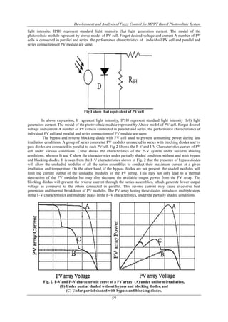
An equivalent circuit of PV cell is show in Fig 1. The below expression for current in the PV cell
equivalent circuit is given by
Wherer Vt is thermal voltage; IPH is light generated current; Is is saturation current of diodes. N is quality factor.
The value of light generated current is in proportion to light intensity(Ir) and
In above expression, Ir represent light intensity, IPH0 represent standard light intensity (Ir0) light
generation current. The model of the photovoltaic module represent by Above model of PV cell. Forget desired
voltage and current A number of PV cells is connected in parallel and series. In above expression, Ir represent](https://image.slidesharecdn.com/h10125864-150115035232-conversion-gate02/85/Development-and-Analysis-of-Fuzzy-Control-for-MPPT-Based-Photovoltaic-System-1-320.jpg)
![International Journal of Engineering Research and Development
e-ISSN: 2278-067X, p-ISSN: 2278-800X, www.ijerd.com
Volume 10, Issue 12 (December 2014), PP.58-64
58
Development and Analysis of Fuzzy Control for MPPT Based
Photovoltaic System
Rapuri Nagaraju 1
, S chandraprakasarao2
1
PG Student, Dept. of Electrical & Electronics Engineering, BVC Institute of Science & Technology
Amalapuram , India
2
Assistant Professor, Dept. of Electrical & Electronics Engineering, Amalapuram, India
Abstract:- In PV system control of Power electronics converters are very essential for the efficient utilization
of the solar System. This paper proposes modified Perturb & Observe Maximum power point tracking (MPPT)
with a fuzzy controller for DC-DC boost converter control in Photovoltaic system under shading and varying
atmospheric conditions. This paper proposes a different approach for MPPT of PV system so as to obtain
maximum power from PV system. In conventional methods, tracking power contains oscillation in the output
power. The Simulation and modeling of Photovoltaic system along with proposed algorithm are done using
MATLAB/SIMLINK software. Form Simulation results shows that P & O based fuzzy controller algorithm is
transient state is fast, less fluctuations and smooth in signal of generated power.
Keywords: Photovoltaic, Fuzzy, Maximum Power Point tracking, Boost converter, Capacitor.
I. INTRODUCTION
In photovoltaic system generates electrical energy from sunlight. At unique point on P-V or I-V curve
of PV system, The PV cell generates maximum power, called Maximum Power Point. Due change in radiation
and temperature the current generation from PV modules also changes [3]. Voltage current a curve of PV
modules shows nonlinearity for different temperature and radiation conditions an optimum load which extracts
the maximum energy from PV cells [3]. There are different approaches for PV module MPPT [4]. They are the
open circuit voltage method, constant current voltage method; short-circuit method, incremental conductance
method and Per-turb and Observe (P&O).
The constant voltage method is the essay method but in this method 80% of the available Maximum
power under different irradiance. By using constant voltage method used to find the output voltage of maximum
power. Like constant voltage method, Constant Current method is used to find short circuit current to maximum
power. P&O method [3] used for the maximum power by changing the Photovoltaic current or voltage and
estimate the change in PV output power. In this paper presents Fuzzy logic controlled maximum point tracking
algorithm is proposed based on P&O method. This fuzzy logic controller is fitted to Photovoltaic system and
Maximum power point under different irradiance conditions are estimated based on the fitted model. BY using
Fuzzy logic Based P&O method able to obtain very fast tracking point with very low steady state oscillations.
The purposed Photo voltaic System, Fuzzy control and P &O algorithm are designed using Matlab/Simulink and
Fuzzy Tool block.
This paper is organized as follows modeling of Photo Voltaic system presents Modeling and
Performance characteristics Section 2. Detail Description about PV System in section 3. The proposed P&O
method and fuzzy logic controller presents in section 4.The simulation results shows in section 5. In last section
conclusion presented.
II. MODELING OF PV CELL AND ITS CHARACTERISTICS
An equivalent circuit of PV cell is show in Fig 1. The below expression for current in the PV cell
equivalent circuit is given by
Wherer Vt is thermal voltage; IPH is light generated current; Is is saturation current of diodes. N is quality factor.
The value of light generated current is in proportion to light intensity(Ir) and
In above expression, Ir represent light intensity, IPH0 represent standard light intensity (Ir0) light
generation current. The model of the photovoltaic module represent by Above model of PV cell. Forget desired
voltage and current A number of PV cells is connected in parallel and series. In above expression, Ir represent](https://image.slidesharecdn.com/h10125864-150115035232-conversion-gate02/75/Development-and-Analysis-of-Fuzzy-Control-for-MPPT-Based-Photovoltaic-System-1-2048.jpg)
![Development and Analysis of Fuzzy Control for MPPT Based Photovoltaic System
63
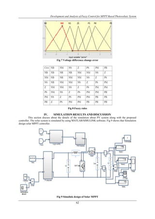
Fig 10 shows that Current, Voltage, power of Solar panel with P&O method and Modified Fuzzy controlled
P&O method. Form fig 10 shows the modified P&O method generates smooth and less ripples voltage currents.
(a) (b)
Fig 10 Current, Voltage, Power Values at different irradiations by (a) P&O method
(b) Modified fuzzy controlled P&O method
V. CONCLUSION
In this paper presented a Photovoltaic system under different irradiations and atmospheric conditions
has been investigated. The proposed tracking of Maximum power point with modified P&O method with fuzzy
logic controller is developed to generate PWM pulse for DC-DC boost converter. The proposed system has
been demonstrated through the results of the simulation in MATLAB/Simulink. Form result concludes that P&O
method generates some oscillations in generated electricity and modified fuzzy controlled P7O method gives
smooth output from the PV cells.
REFERENCES
[1]. N. Femia, G. Petrone, G. Spagnuolo, M. Vitelli, Optimization of perturb and observe maximum power
point tracking method, IEEE Transactions on Power Electronics 20 (2005) 963–973.
[2]. A. Safari, S. Mekhilef, Simulation and hardware implementation of incremental conductance MPPT
with direct control method using Cuk converter, IEEE Transactions on Industrial Electronics 58 (2011)
1154–1161.
[3]. H.H. Lee, The new maximum power point tracking algorithm using ANN-based solar PV systems,
IEEE Network Conference 3 (2010) 2179–2184.
[4]. A. Messai, A. Mellit, A.M. Pavan, A. Guessoum, H. Mekki, FPGA-based implementation of a fuzzy
controller (MPPT) for photovoltaic module, Energy Conversion and Management 52 (2011) 2695–
2704.
[5]. Y. Shaiek, M. Ben Smida, A. Sakly, M.F. Mimouni, Comparison between conventional methods and
GA approach for maximum power point tracking of shaded solar PV generators, Solar Energy 90 (2013)
107–122.
[6]. M. Miyatake, F. Toriumi, T. Endo, N. Fujii, A novel MPPT controlling several converters connected to
PV arrays with PSO technique, Proceedings of Power Electronics Applications in European
Conference 11 (2007) 1–10.
[7]. Y.-H. Ji, D.-Y. Jung, J.-G. Kim, J.-H. Kim, T.-W. Lee, C.-Y. Won, A real maximum power point
tracking method for mismatching compensation in PV array under partially shaded conditions, IEEE
Transactions on Power Electronics 26 (2011) 1001–1009.](https://image.slidesharecdn.com/h10125864-150115035232-conversion-gate02/85/Development-and-Analysis-of-Fuzzy-Control-for-MPPT-Based-Photovoltaic-System-6-320.jpg)
![Development and Analysis of Fuzzy Control for MPPT Based Photovoltaic System
64
[8]. M. Miyatake, M. Veerachary, F. Toriumi, N. Fujii, H. Ko, Maximum power point tracking of multiple
photovoltaic arrays: a PSO approach, IEEE Transactions on Aerospace and Electronic Systems 47
(2011) 367–380.
[9]. H. Patel, V. Agarwal, Maximum power point tracking scheme for PV systems operating under partially
shaded conditions, IEEE Transactions on Industrial Electronics 55 (2008) 1689–1698.
[10]. P. Rathika, D. Devaraj, Fuzzy logic-based approach for adaptive hysteresis band and DC voltage
control in shunt active filter, International Journal of Computer and Electrical Engineering 2 (2010)
1793–8163.
[11]. Giuseppe Fedele, Domenico Franscino, “Spectral analysis of a class of DC-AC PWM inverters by
Kepteyn Series” IEEE Transaction on power electronics, vol. 25,No. 4,April 2010, pg.839-849.](https://image.slidesharecdn.com/h10125864-150115035232-conversion-gate02/85/Development-and-Analysis-of-Fuzzy-Control-for-MPPT-Based-Photovoltaic-System-7-320.jpg)

This document presents a study on developing and analyzing a fuzzy control system for maximum power point tracking (MPPT) in a photovoltaic system. It proposes using a modified perturb and observe (P&O) MPPT algorithm with a fuzzy controller to track the maximum power point under varying conditions. The system is modeled and simulated in MATLAB/Simulink. Simulation results show that the fuzzy controlled P&O method produces smoother output power with less fluctuation compared to the conventional P&O method.