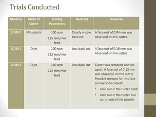
INTERNSHIP AT LMTG
Presented by:
Ashish Sethi
Indian Institute of Technology
(Banaras Hindu University),
Varanasi
(May-June 2013)
Steam Turbine
• Thermal energy from pressurized steam does mechanical
work on a rotating output shaft.
• Drives an electrical generator which produces power.
• Increase in thermodynamic efficiency by using multiple stages
in the expansion of steam.
Projects: Past and Present
Projects Undertaken
By LMTG

Power
Rating

APPDCL-1

800 MW

APPDCL-2

800 MW

JP-1

660 MW

MH-1

660 MW

Rajpura-1

700 MW

JP-2

660 MW

MH-2

660 MW

Rajpura-2

700 MW

MH-3

660 MW

USA

660 MW

Rabigh IWSPP

120 MW

RRVUNL-1

660 MW

RRVUNL-2

660 MW

• Supercritical range: 5001000 MW
• Refers to main steam
operating conditions
being above critical
pressure of water (221.5
bar)
• At a pressure of 242 bar,
main steam and reheat
steam temperatures are
565ºC and 593ºC
respectively.
The Process Flow
Fabrication

Heat
Treatment

Shot
Blasting

Assembly

Machining

Painting

Shot
Blasting

Painting
Layout of the Production Department
Machine Shop T3
• Planomillers: Gen 6 and ST 13

Planing

Milling

Planomilling

 Axes are X, Y, Z, W and C.
 Bed moves, columns are stationary.
 Attachments include right angle, universal, extension and surfacing.

• Horizontal Boring Machines (HBMs): UDM 1, UDM 2, UDM 5, ST 15
 Operations such as drilling, boring, facing, back spot facing, turning,
etc. can be performed.
 Possible axes include X, Y, Z, W, V, B.
 Attachments include right angle, universal, facing and profiling,
offset.
Machine Shop T3 (contd.)
• Vertical Turning Lathes (VTLs): Gen 7 and ST 9
 Facing, ID turning, OD turning, chamfering etc. performed using a
single point tool.
 Axes are X, Z and W.

• Electric Discharge Machine:
 Used for machining thin slits in blades and grooves for caulking.
 Used for machining hard materials like HSS.
 Copper electrode is used.
 Job is completely submerged in dielectric oil, which acts as a
capacitive medium.
 When voltage is sufficiently high, electric arc is generated which
jumps across dielectric medium and erodes metal.
Machining Tools and Operations
Operation

Purpose

Tool

Facing

Generation of a flat
surface

Face mill, Shoulder
mill

Turning

Generation of a
cylindrical surface

Single point
cutting tool

Drilling

Making holes

Drills

Boring

Enlarging holes, ID
machining

Boring tool

Tapping

Making internal
threads

Taps

Reaming

Finishing of holes

Reamer

Chamfering

Generation of
Chamfering tool
angled surfaces to
remove sharp edges

Slot Milling

Machining of slots

End mills
Cutting Parameters
•
where,
V is the cutting velocity
N is the required rpm
D, for turning – diameter of job
for facing – diameter of cutter
for drilling – diameter of drill bit
For tools with multiple inserts,

where,
Feed rate is in mm/min
fz is the feed/revolution/tooth
PROJECT I: TOOL DEVELOPMENT
Objective: Developing tool for back spot facing of
diameter 46 mm for “D4” detail in ash lock
Challenging Aspects of Ash
Lock Machining
• Ash lock has two openings (A1 and A2). The machine ram
cannot enter A2.
• Large spindle overhang makes it difficult to maintain
concentricity of various IDs.
• Vibrations arise as machining operations take place at very
large distances from the ram.
• Not possible to mount the ash lock at the centre of the table.
On rotating the rotary table, the centre of various IDs gets
displaced.
Common Back Spot Facing Tools
• Centric Tool:
 Rotates about its centre.
 Has a removable head.
 Suitable in situations where back spot diameter is much more than passing
diameter.

• Eccentric Tool:
 Insert is offset from the central axis of tool.
 Efficient as no manual intervention is required.
 Suitable when difference between spot face diameter and passing diameter
is less.

• Tool with HSS Bit:
 Boring bar with slot at its end to hold the HSS bit.
 Similar to centric tool, as bar is first passed through the bore and then the bit
is inserted.

• Butterfly Tool:
 Has a foldable wing.
 No manual interruption.
The D4 Detail
Problems Faced and Possible Solutions
• Unavailability of tool of sufficient length and required passing
diameter. Length of the tool should be more than
(1350 + 50 + 50 – 1000) = 450 mm

Maximum spindle travel
Clearance between ram and A2
Minimum thickness of the flange
Distance between A2 and D4

• Vibrations in the tool because:
 Spindle would be at close to its maximum extension.
 The length of the tool is large.
 The diameter of the bar is small.
Problems Faced and Possible Solutions (contd.)
Suggested solution:
• The bar of the tool to be in the form of a stepped shaft.
• The bar of the centric tool is internally threaded at its end, for
attaching the removable head.
• A short tool of this type with a large passing diameter could be
attached to another with a passing diameter less than 27 mm,
creating a stepped bar.
• External threads would have to be machined on the tool with
smaller diameter, to mesh with the internal threads present in
the first tool.
Problems Faced and Possible Solutions (contd.)
• Problem of chip evacuation because of large depth of back
spot.
Suggested solution:
 Using a tool with HSS bit. Proper angles can be provided to guide
chip flow.
 Machining of a helical path in the removable head of centric tool.

• If we use a tool with HSS bit, setting the bit to make the
required back spot diameter is time consuming.
Suggested solution:
 Step to be created on the bit at a pre-determined distance from
the cutting tip.
 Stepped part will not enter the slot.
Problems Faced and Possible Solutions (contd.)

Cutting
Force

• Large spindle overhang results in drooping
of machine spindle.
• Cutting forces on the bit tend to reduce the
diameter of the back spot.
• Difficult to accurately predict the diameter
formed for a particular length of tool bit
cutting edge.
Suggested solution:
 Preparation of tool bit for a slightly larger
diameter.
 Modification to length of cutting edge
depending on outcome of trials.
The Final Tool
• Boring bar of length 450 mm and passing
diameter 26 mm used.
• Longer adaptor not originally meant for
this boring bar used.
• Slot of 9.5 x 9.5 mm for housing HSS bit.
• Outer part of the bar is ground to
smaller diameter.
The HSS Bit
Diameter of the boring bar = 26 mm
Radial distance between the bore and the bar = 0.5 mm
Difference between spot face diameter and bore diameter = 19 mm
So, Radial distance between bore and OD of spot face = 9.5 mm
Allowance for cutting force problem = 0.5 mm
So, distance from step to tip of tool = 26 + 0.5 + 9.5 + 0.5 = 36.5 mm

• Three relief angles – rake angle, clearance angle, end cutting
edge angle
• Step was removed one side and pushed inwards.
Machining of HSS Bit
Step was created on VMC in T6

Required angles were given on Tool
and Cutter Grinder in T6

Required length (including the step)
was cut off from the bar on EDM in T3
Step was pushed inward on required
side on Tool and Cutter Grinder in T6
Trials Conducted
Distance
from step Spindle
to cutting extension
tip (mm)
(mm)

Diameter of back
spot formed

Remarks

0.7 mm material was subsequently
ground off from the end of the bit.
0.1 mm material was subsequently
ground off from the end of the bit.
Very long chips were formed and good
surface finish was obtained with
coolant.
Surface finish without coolant was not
very good.
Repeatability of the bit was confirmed.
Long chips and good surface finish was
obtained with a feed rate of 1 mm/min.
Increasing the feed rate to 1.5 and 2
mm/min degraded the surface finish.
Repeatability of the second bit was
confirmed.

36.9

500

48.4

36.2

500

46.8

36.1

500

46.4

36.1

1100

46.2

Bit II

36.1
36.2

1100
800

46.2
46.8

(for
clockwise
spindle
rotation)

36.2

800

46.8

Bit I
(for counter
clockwise
spindle
rotation)
PROJECT II: SURFACE FINISH ANALYSIS
Objective: Analyzing surface finish obtained using wiper
cutter on Horizontal Boring Machine (of Collet make) –
UDM 1
Wiper Cutter
• Used for finishing of plane surfaces.
• Not a single point cutting tool. Whole
cutting edge ‘wipes’ off the high points.
• Can be done using a single insert, or
more than one.
• If more than one insert is used, one
forms the roughing edge and the other
forms the finishing edge.
• The finishing edge is placed 10-20
microns below the roughing edge.
• The finishing edge is radially inward in
comparison to roughing edge.
• Mitsubishi wiper cutter can hold 2
inserts, Dijet can hold 4.
Operation of wiper cutters with single insert on UDM 1 is
generating extensive back cut marks on the surface.
Trials Conducted
Machine

Make of
Cutter

Cutting
Parameters

Back Cut

UDM 1

Mitsubishi

100 rpm

Clearly visible
back cut

A face out of 0.04 mm was
observed on the cutter.

Less back cut

A face out of 0.16 mm was
observed on the cutter.

Less back cut

Cutter was removed and set
again. A face out of 0.12 mm
was observed on the cutter.
Possible reasons for this face
out were discussed:

125 mm/min
feed
UDM 1

Dijet

100 rpm
125 mm/min
feed

UDM 1

Dijet

100 rpm
125 mm/min
feed

Remarks

•

Face out in the cutter itself

•

Face out in the cutter due
to run out of the spindle
Machine

Gen 6

Gen 6

Make of
Cutter
Mitsubishi

Cutting
Parameters
220 rpm

Mitsubishi

300 mm/min
feed
220 rpm
300 mm/min
feed

Gen 6

Mitsubishi

220 rpm
300 mm/min
feed

Gen 6

Mitsubishi

250 rpm
300 mm/min
feed

Back Cut

Remarks

Visible back
cut

Face out on the cutter observed.

Visible back
cut

A different Mitsubishi cutter was
used. Face out of 0.08 mm
observed. Insert was kept on the
lower end of the cutter.
Replaced insert. Other conditions
same as before.

Visible back
cut

Slightly less
back cut

Concluded that problem not with
the cutter.
Insert position changed from lower
end to upper end. Possible reason
for back cut could be spindle run
out.
•

Spindle run out of UDM 1 is 0.5
mm.

•
ST 13

Mitsubishi

300 rpm
350 mm/min
feed

No back cut

Spindle run out of Gen 6 is 0.25
mm.
No spindle run out on ST 13.
Reason for back cut found to be
spindle run out.
Suggestions for Improvement in Shop
Reasons for formation of such an irregularly shaped pit
were discussed:
• If the table of EDM is not locked, it can deviate
slightly if a jerk is encountered for any reason.
• There may be an error in initial setting of the
electrode by the operator.
Suggestion:
Job could be covered with an insulating material in
areas where no cutting is to take place.
Suggestions for Improvement
in Shop (contd.)
• Using ATC (Automatic Tool Change) in Gen 6 Planomiller
machine.
 Offset of tools needed for the next planned job can be taken and
their values stored in the ATC beforehand.
 Tools can be stored in the ATC.
 Time required for completion of job can be reduced.

• Leakage from the roof over Machine Shop T6.
 Machines such as Tool and Cutter Grinder can not be used at
times.
 Possibility of damage to the machine.
Internship at LMTG

Internship at LMTG

  • 1.
    INTERNSHIP AT LMTG Presentedby: Ashish Sethi Indian Institute of Technology (Banaras Hindu University), Varanasi (May-June 2013)
  • 2.
    Steam Turbine • Thermalenergy from pressurized steam does mechanical work on a rotating output shaft. • Drives an electrical generator which produces power. • Increase in thermodynamic efficiency by using multiple stages in the expansion of steam.
  • 3.
    Projects: Past andPresent Projects Undertaken By LMTG Power Rating APPDCL-1 800 MW APPDCL-2 800 MW JP-1 660 MW MH-1 660 MW Rajpura-1 700 MW JP-2 660 MW MH-2 660 MW Rajpura-2 700 MW MH-3 660 MW USA 660 MW Rabigh IWSPP 120 MW RRVUNL-1 660 MW RRVUNL-2 660 MW • Supercritical range: 5001000 MW • Refers to main steam operating conditions being above critical pressure of water (221.5 bar) • At a pressure of 242 bar, main steam and reheat steam temperatures are 565ºC and 593ºC respectively.
  • 4.
  • 5.
    Layout of theProduction Department
  • 6.
    Machine Shop T3 •Planomillers: Gen 6 and ST 13 Planing Milling Planomilling  Axes are X, Y, Z, W and C.  Bed moves, columns are stationary.  Attachments include right angle, universal, extension and surfacing. • Horizontal Boring Machines (HBMs): UDM 1, UDM 2, UDM 5, ST 15  Operations such as drilling, boring, facing, back spot facing, turning, etc. can be performed.  Possible axes include X, Y, Z, W, V, B.  Attachments include right angle, universal, facing and profiling, offset.
  • 7.
    Machine Shop T3(contd.) • Vertical Turning Lathes (VTLs): Gen 7 and ST 9  Facing, ID turning, OD turning, chamfering etc. performed using a single point tool.  Axes are X, Z and W. • Electric Discharge Machine:  Used for machining thin slits in blades and grooves for caulking.  Used for machining hard materials like HSS.  Copper electrode is used.  Job is completely submerged in dielectric oil, which acts as a capacitive medium.  When voltage is sufficiently high, electric arc is generated which jumps across dielectric medium and erodes metal.
  • 8.
    Machining Tools andOperations Operation Purpose Tool Facing Generation of a flat surface Face mill, Shoulder mill Turning Generation of a cylindrical surface Single point cutting tool Drilling Making holes Drills Boring Enlarging holes, ID machining Boring tool Tapping Making internal threads Taps Reaming Finishing of holes Reamer Chamfering Generation of Chamfering tool angled surfaces to remove sharp edges Slot Milling Machining of slots End mills
  • 9.
    Cutting Parameters • where, V isthe cutting velocity N is the required rpm D, for turning – diameter of job for facing – diameter of cutter for drilling – diameter of drill bit For tools with multiple inserts, where, Feed rate is in mm/min fz is the feed/revolution/tooth
  • 10.
    PROJECT I: TOOLDEVELOPMENT Objective: Developing tool for back spot facing of diameter 46 mm for “D4” detail in ash lock
  • 11.
    Challenging Aspects ofAsh Lock Machining • Ash lock has two openings (A1 and A2). The machine ram cannot enter A2. • Large spindle overhang makes it difficult to maintain concentricity of various IDs. • Vibrations arise as machining operations take place at very large distances from the ram. • Not possible to mount the ash lock at the centre of the table. On rotating the rotary table, the centre of various IDs gets displaced.
  • 12.
    Common Back SpotFacing Tools • Centric Tool:  Rotates about its centre.  Has a removable head.  Suitable in situations where back spot diameter is much more than passing diameter. • Eccentric Tool:  Insert is offset from the central axis of tool.  Efficient as no manual intervention is required.  Suitable when difference between spot face diameter and passing diameter is less. • Tool with HSS Bit:  Boring bar with slot at its end to hold the HSS bit.  Similar to centric tool, as bar is first passed through the bore and then the bit is inserted. • Butterfly Tool:  Has a foldable wing.  No manual interruption.
  • 13.
  • 14.
    Problems Faced andPossible Solutions • Unavailability of tool of sufficient length and required passing diameter. Length of the tool should be more than (1350 + 50 + 50 – 1000) = 450 mm Maximum spindle travel Clearance between ram and A2 Minimum thickness of the flange Distance between A2 and D4 • Vibrations in the tool because:  Spindle would be at close to its maximum extension.  The length of the tool is large.  The diameter of the bar is small.
  • 15.
    Problems Faced andPossible Solutions (contd.) Suggested solution: • The bar of the tool to be in the form of a stepped shaft. • The bar of the centric tool is internally threaded at its end, for attaching the removable head. • A short tool of this type with a large passing diameter could be attached to another with a passing diameter less than 27 mm, creating a stepped bar. • External threads would have to be machined on the tool with smaller diameter, to mesh with the internal threads present in the first tool.
  • 16.
    Problems Faced andPossible Solutions (contd.) • Problem of chip evacuation because of large depth of back spot. Suggested solution:  Using a tool with HSS bit. Proper angles can be provided to guide chip flow.  Machining of a helical path in the removable head of centric tool. • If we use a tool with HSS bit, setting the bit to make the required back spot diameter is time consuming. Suggested solution:  Step to be created on the bit at a pre-determined distance from the cutting tip.  Stepped part will not enter the slot.
  • 17.
    Problems Faced andPossible Solutions (contd.) Cutting Force • Large spindle overhang results in drooping of machine spindle. • Cutting forces on the bit tend to reduce the diameter of the back spot. • Difficult to accurately predict the diameter formed for a particular length of tool bit cutting edge. Suggested solution:  Preparation of tool bit for a slightly larger diameter.  Modification to length of cutting edge depending on outcome of trials.
  • 18.
    The Final Tool •Boring bar of length 450 mm and passing diameter 26 mm used. • Longer adaptor not originally meant for this boring bar used. • Slot of 9.5 x 9.5 mm for housing HSS bit. • Outer part of the bar is ground to smaller diameter.
  • 19.
    The HSS Bit Diameterof the boring bar = 26 mm Radial distance between the bore and the bar = 0.5 mm Difference between spot face diameter and bore diameter = 19 mm So, Radial distance between bore and OD of spot face = 9.5 mm Allowance for cutting force problem = 0.5 mm So, distance from step to tip of tool = 26 + 0.5 + 9.5 + 0.5 = 36.5 mm • Three relief angles – rake angle, clearance angle, end cutting edge angle • Step was removed one side and pushed inwards.
  • 20.
    Machining of HSSBit Step was created on VMC in T6 Required angles were given on Tool and Cutter Grinder in T6 Required length (including the step) was cut off from the bar on EDM in T3 Step was pushed inward on required side on Tool and Cutter Grinder in T6
  • 21.
    Trials Conducted Distance from stepSpindle to cutting extension tip (mm) (mm) Diameter of back spot formed Remarks 0.7 mm material was subsequently ground off from the end of the bit. 0.1 mm material was subsequently ground off from the end of the bit. Very long chips were formed and good surface finish was obtained with coolant. Surface finish without coolant was not very good. Repeatability of the bit was confirmed. Long chips and good surface finish was obtained with a feed rate of 1 mm/min. Increasing the feed rate to 1.5 and 2 mm/min degraded the surface finish. Repeatability of the second bit was confirmed. 36.9 500 48.4 36.2 500 46.8 36.1 500 46.4 36.1 1100 46.2 Bit II 36.1 36.2 1100 800 46.2 46.8 (for clockwise spindle rotation) 36.2 800 46.8 Bit I (for counter clockwise spindle rotation)
  • 22.
    PROJECT II: SURFACEFINISH ANALYSIS Objective: Analyzing surface finish obtained using wiper cutter on Horizontal Boring Machine (of Collet make) – UDM 1
  • 23.
    Wiper Cutter • Usedfor finishing of plane surfaces. • Not a single point cutting tool. Whole cutting edge ‘wipes’ off the high points. • Can be done using a single insert, or more than one. • If more than one insert is used, one forms the roughing edge and the other forms the finishing edge. • The finishing edge is placed 10-20 microns below the roughing edge. • The finishing edge is radially inward in comparison to roughing edge. • Mitsubishi wiper cutter can hold 2 inserts, Dijet can hold 4. Operation of wiper cutters with single insert on UDM 1 is generating extensive back cut marks on the surface.
  • 24.
    Trials Conducted Machine Make of Cutter Cutting Parameters BackCut UDM 1 Mitsubishi 100 rpm Clearly visible back cut A face out of 0.04 mm was observed on the cutter. Less back cut A face out of 0.16 mm was observed on the cutter. Less back cut Cutter was removed and set again. A face out of 0.12 mm was observed on the cutter. Possible reasons for this face out were discussed: 125 mm/min feed UDM 1 Dijet 100 rpm 125 mm/min feed UDM 1 Dijet 100 rpm 125 mm/min feed Remarks • Face out in the cutter itself • Face out in the cutter due to run out of the spindle
  • 25.
    Machine Gen 6 Gen 6 Makeof Cutter Mitsubishi Cutting Parameters 220 rpm Mitsubishi 300 mm/min feed 220 rpm 300 mm/min feed Gen 6 Mitsubishi 220 rpm 300 mm/min feed Gen 6 Mitsubishi 250 rpm 300 mm/min feed Back Cut Remarks Visible back cut Face out on the cutter observed. Visible back cut A different Mitsubishi cutter was used. Face out of 0.08 mm observed. Insert was kept on the lower end of the cutter. Replaced insert. Other conditions same as before. Visible back cut Slightly less back cut Concluded that problem not with the cutter. Insert position changed from lower end to upper end. Possible reason for back cut could be spindle run out. • Spindle run out of UDM 1 is 0.5 mm. • ST 13 Mitsubishi 300 rpm 350 mm/min feed No back cut Spindle run out of Gen 6 is 0.25 mm. No spindle run out on ST 13. Reason for back cut found to be spindle run out.
  • 26.
    Suggestions for Improvementin Shop Reasons for formation of such an irregularly shaped pit were discussed: • If the table of EDM is not locked, it can deviate slightly if a jerk is encountered for any reason. • There may be an error in initial setting of the electrode by the operator. Suggestion: Job could be covered with an insulating material in areas where no cutting is to take place.
  • 27.
    Suggestions for Improvement inShop (contd.) • Using ATC (Automatic Tool Change) in Gen 6 Planomiller machine.  Offset of tools needed for the next planned job can be taken and their values stored in the ATC beforehand.  Tools can be stored in the ATC.  Time required for completion of job can be reduced. • Leakage from the roof over Machine Shop T6.  Machines such as Tool and Cutter Grinder can not be used at times.  Possibility of damage to the machine.