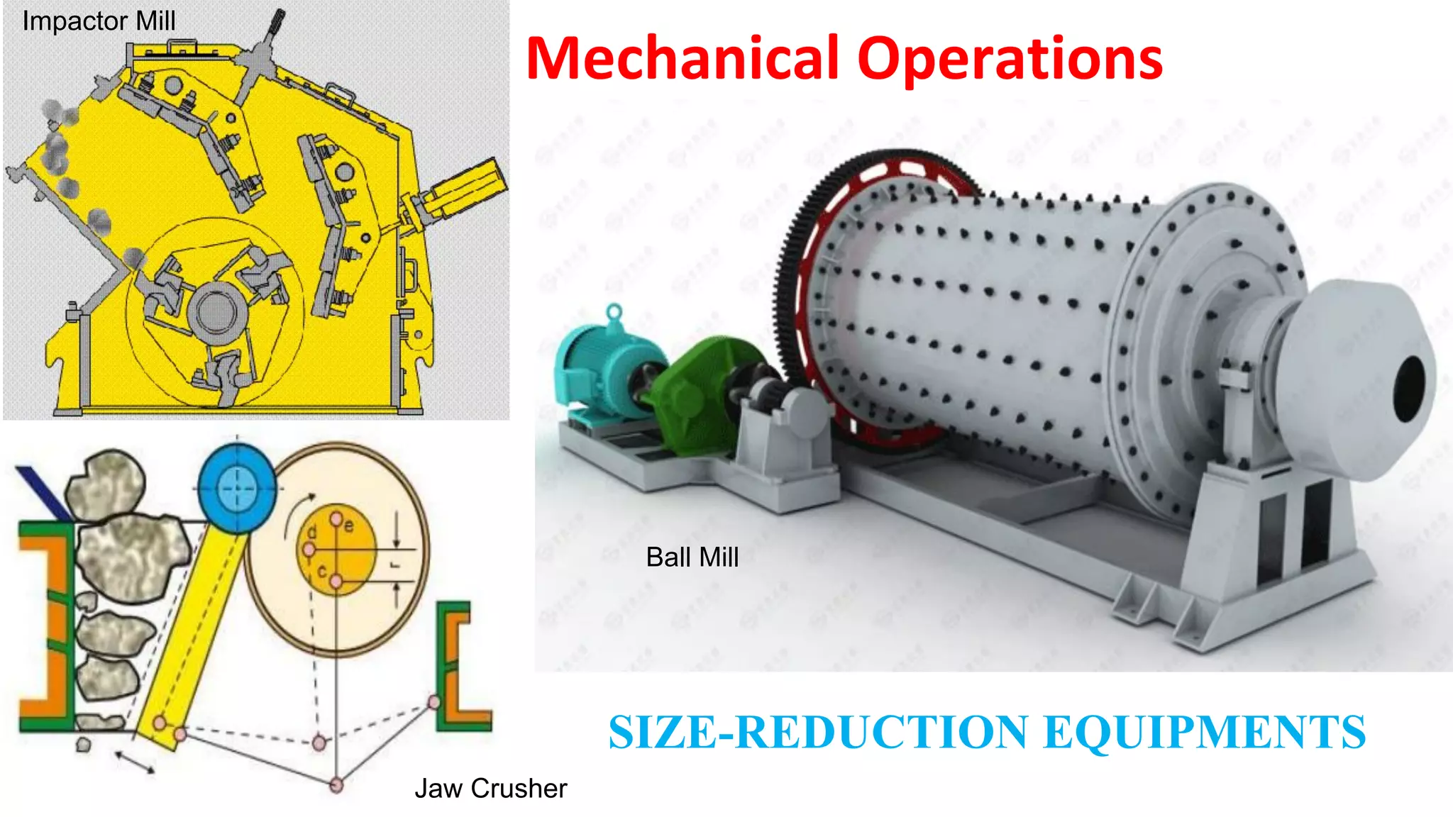
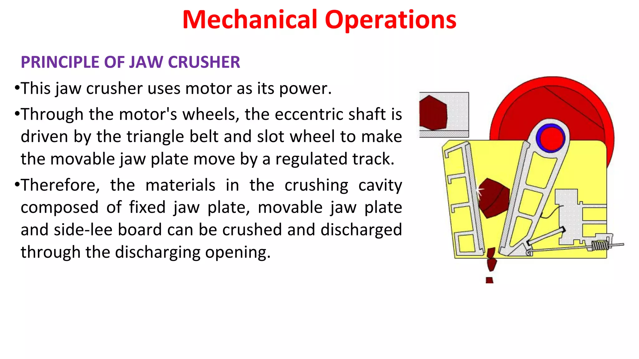
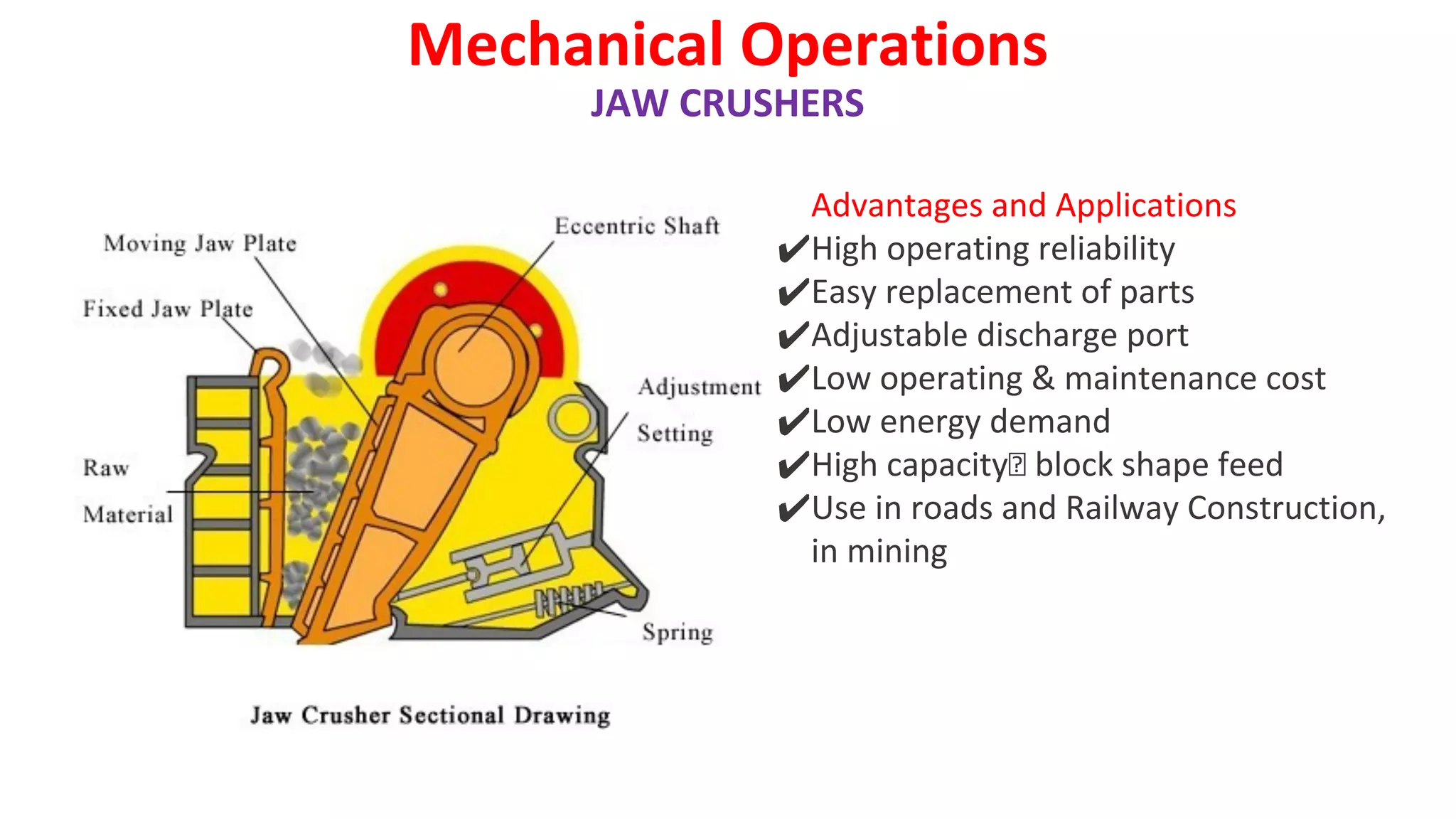
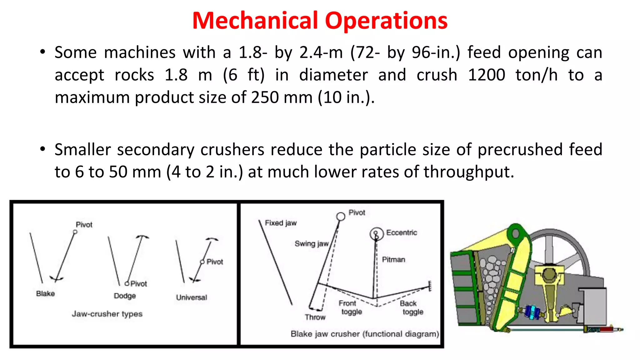
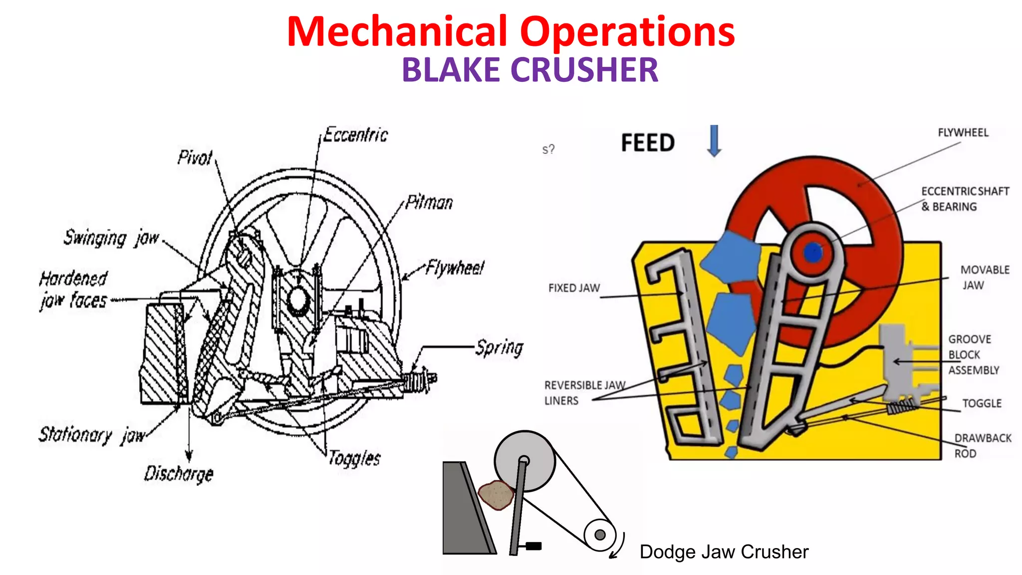
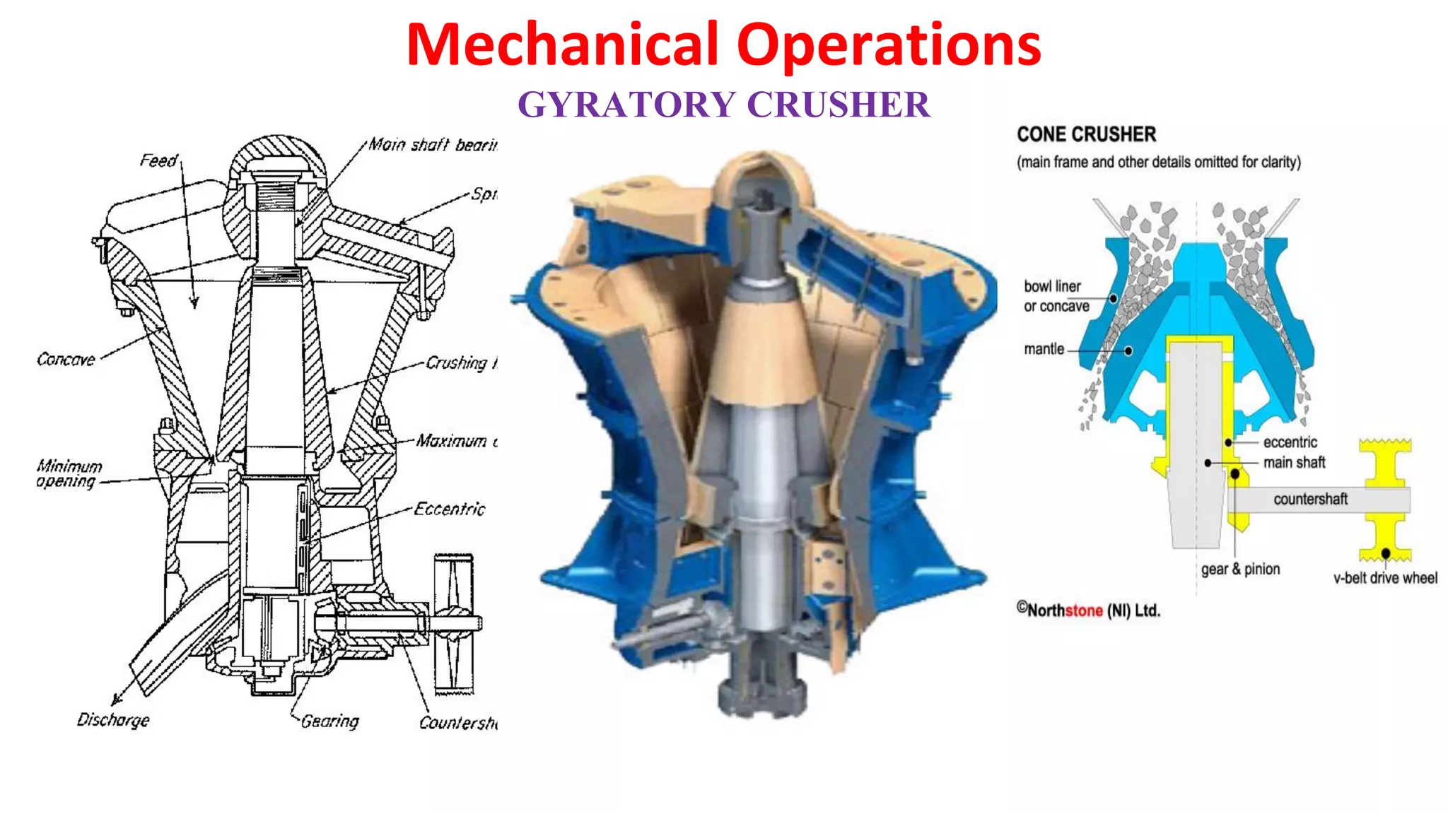
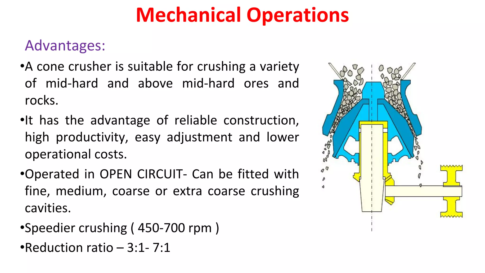
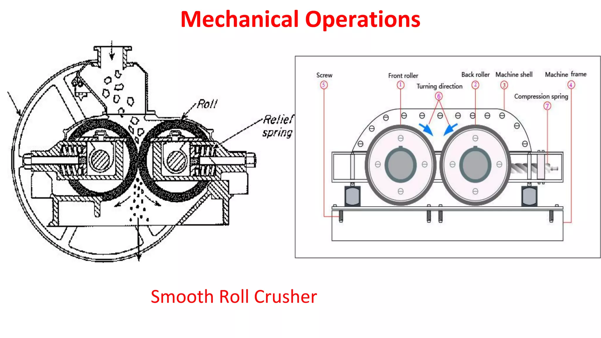
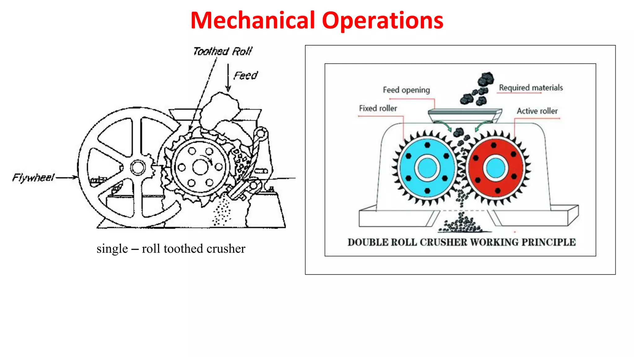
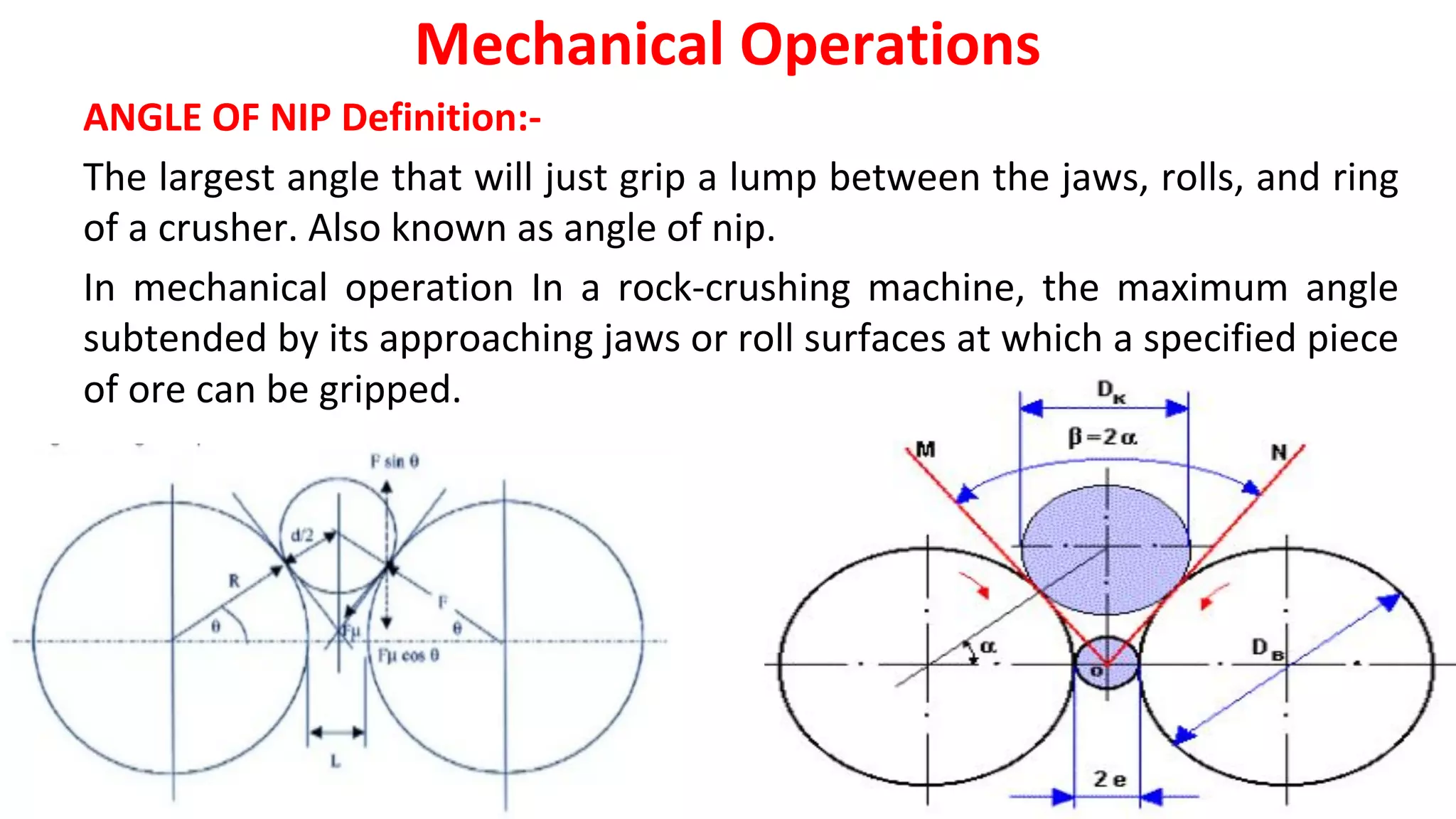
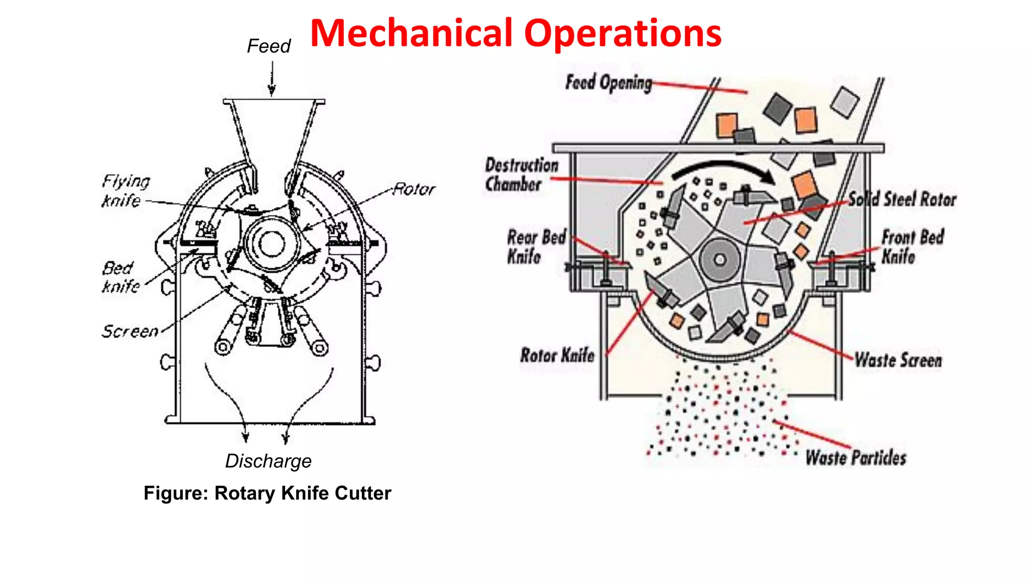
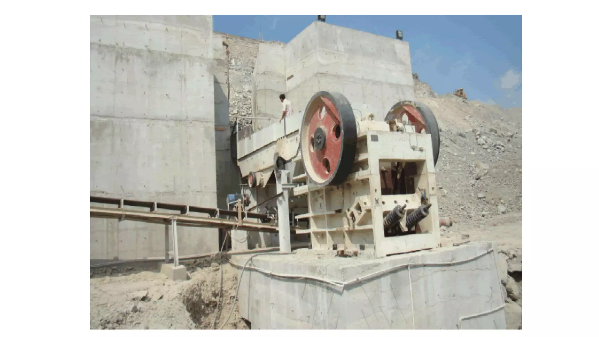
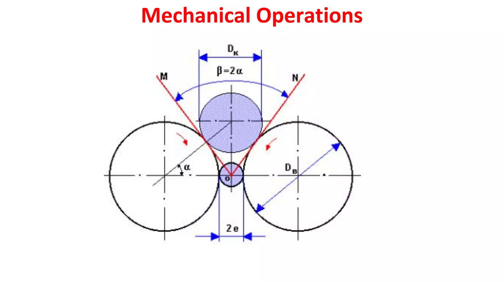
SIZE-REDUCTION EQUIPMENTS
Mechanical Operations
Ball Mill
Impactor Mill
Jaw Crusher
Size reduction equipment is divided into crushers, grinders, ultrafine grinders, and
cutting machines.
•Crusher does the heavy work of breaking large pieces of solid material into small
lumps.
•A primary crusher operates on run-of-mine material accepting anything that comes
from mine face and breaking it into 150 to 250 mm lumps.
•A secondary crusher reduces these lumps into particles maybe 6mm in size.
•Grinders reduce crushed feed to powder.
•The product from an intermediate grinder might pass a 40-mesh screen; most of the
product from a fine grinder would pass a 200-mesh screen with a 74micrometers
opening.
•An ultrafine grinder accepts feed particles no larger than 6mm and the product size is
typically 1 to 5 micrometers
•Cutters give particles of definite size and shape, 2 to 10mm in length.
Mechanical Operations
C. Ultrafine grinders
1. Hammer mills with internal classification
2. Fluid-energy mills
3. Agitated mills
D. Cutting machines
1. Knife cutters; slitters
Mechanical Operations
The principal types of size-reduction machines are as follows:
A. Crushers (coarse and fine)
1. Jaw crushers
2. Gyratory crushers
3. Crushing rolls
B. Grinders (intermediate and fine)
1. Hammer mills; impactors
2. Rolling-compression mills
✔ Bowl mills
✔ Roller mills
3. Attrition mills
4. Tumbling mills
1. Rod mills
✔ Ball mills; pebble mills
✔ Tube mills; compartment mills
No Process Size reduction
1 Explosive shattering Infinite size to 1 m
2 Primary crushing 1m – 100 mm
3 Secondary crushing 100 mm- 10 mm
4 Coarse grinding 10 mm- 1 mm
5 Fine grinding 1 mm- 100 microns
6 Very fine grinding 100 microns – 10 microns
7 Superfine grinding 10 microns- 1 micron
Mechanical Operations
These machines do their work in definitely different ways.
Compression is the characteristic action of crushers.
Grinders employ impact and attrition, sometimes combined with compression.
Ultrafine grinders operate principally by attrition.
A cutting action is of course characteristic of cutters, and slitters.
CRUSHERS
Crushers are slow-speed machines for coarse reduction of large quantities of solids.
The main types are jaw crushers, gyratory crushers, smooth-roll crushers, and
toothed-roll crushers.
The first three operate by compression and can break large lumps of very hard
materials, as in the primary and secondary reduction of rocks and ores.
Toothed-roll crushers tear the feed apart as well as crushing it; they handle softer feeds
like coal, bone, and soft shale.
Mechanical Operations
PRINCIPLE OF JAW CRUSHER
•This jaw crusher uses motor as its power.
•Through the motor's wheels, the eccentric shaft is
driven by the triangle belt and slot wheel to make
the movable jaw plate move by a regulated track.
•Therefore, the materials in the crushing cavity
composed of fixed jaw plate, movable jaw plate
and side-lee board can be crushed and discharged
through the discharging opening.
Mechanical Operations
JAW CRUSHERS
•In a jaw crusher feed is admitted between two jaws, set to form a V open at the top.
•One jaw is fixed, jaw is nearly vertical and does not move, the other, the swinging jaw,
reciprocates in a horizontal plane. It makes an angle of 200
to 30° with the fixed jaw.
•It is driven by an eccentric so that it applies great compressive force to lumps caught
between the jaws. The jaw faces are flat or slightly bulged; they may carry shallow
horizontal grooves.
•Large lumps caught between the upper parts of the jaws are broken, drop into the narrow
space below, and are re-crushed the next time the jaws close.
•After sufficient reduction they drop out the bottom of the machine. The jaws open and
close 250 to 400 times per minute.
Mechanical Operations
JAW CRUSHERS
Mechanical Operations
Advantages and Applications
✔High operating reliability
✔Easy replacement of parts
✔Adjustable discharge port
✔Low operating & maintenance cost
✔Low energy demand
✔High capacity block shape feed
✔Use in roads and Railway Construction,
in mining
• Jaw crushers of various models are widely used in the crushing operation in mining,
metallurgy, construction, highway, railway, irrigation and Chemical industries.
• Jaw crushers have the features of high reduction ratio, even powder-sizes, low power
consumption and easy maintenance.
• The crushing strength of the jaw crusher material is up to 350 Mpa.
• Jaw crusher reduces large size rocks or ore by compressing, a fixed jaw, mounted in a V”
arrangement is the stationary breaking surface, while the moveable jaw plate uses force
on the rock by compressing it against the fixed jaw plate.
• The space at bottom of the “V”, associated jaw plate, is the output size gap, or the
maximum size of the crushed product.
• Due to the features of simple structure, reliable performance, convenient maintenance
and safe use.
Mechanical Operations
BLAKE CRUSHER:
•The most common type of jaw crusher is the Blake crusher, in Fig.
•In this machine an eccentric drives a pitman connected to two toggle plates,
one of which is pinned to the frame and the other to the swinging jaw.
•The pivot point is at the top of the movable jaw or above the top of the jaws
on the centerline of the jaw opening.
•The greatest amount of motion is at the bottom of the V, which means that
there is little tendency for a crusher of this kind to choke.
Mechanical Operations
• Some machines with a 1.8- by 2.4-m (72- by 96-in.) feed opening can
accept rocks 1.8 m (6 ft) in diameter and crush 1200 ton/h to a
maximum product size of 250 mm (10 in.).
• Smaller secondary crushers reduce the particle size of precrushed feed
to 6 to 50 mm (4 to 2 in.) at much lower rates of throughput.
Mechanical Operations
BLAKE CRUSHER
Mechanical Operations
Dodge Jaw Crusher
GYRATORY CRUSHERS
• A gyratory crusher may be looked upon as a jaw crusher with circular jaws, between
which material is being crushed at some point at all times.
• A conical crushing head gyrates inside a funnel-shaped casing, open at the top. As
shown in Fig., the crushing head is carried on a heavy shaft pivoted at the top of the
machine.
• An eccentric drives the bottom end of the shaft. At any point on the periphery of the
casing, therefore, the bottom of the crushing head moves toward, and then away from,
the stationary wall.
• Solids caught in the V-shaped space between the head and the casing are broken and
re-broken until they pass out the bottom. The crushing head is free to rotate on the
shaft and turns slowly because of friction with the material being crushed.
Mechanical Operations
• The speed of the crushing head is typically 125 to 425 gyrations per minute. Because
some part of the crushing head is working at all times, the discharge from a gyratory is
continuous instead of intermittent as in a jaw crusher.
• The load on the motor is nearly uniform; less maintenance is required than with a jaw
crusher; and the power requirement per ton of material crushed is smaller.
• The biggest gyrators handle up to 4500 ton/h.
• The capacity of a gyratory crusher varies with the jaw setting, the impact strength of the
feed, and the speed of gyration of the machine.
• The capacity is almost independent of the compressive strength of the material being
crushed.
Mechanical Operations
GYRATORY CRUSHERS
GYRATORY CRUSHER
Mechanical Operations
Advantages:
•A cone crusher is suitable for crushing a variety
of mid-hard and above mid-hard ores and
rocks.
•It has the advantage of reliable construction,
high productivity, easy adjustment and lower
operational costs.
•Operated in OPEN CIRCUIT- Can be fitted with
fine, medium, coarse or extra coarse crushing
cavities.
•Speedier crushing ( 450-700 rpm )
•Reduction ratio – 3:1- 7:1
Mechanical Operations
Roll crushers
•Roll crushers are used for producing additional reductions in the sizes of stone after the
output of a quarry has been subjected to one or more stages of prior crushing.
•Roll crushers have a theoretical MAXIMUM reduction ratio of 4:1.
•If a 2 inch particle is fed to the roll crusher the absolute smallest size one could expect
from the crusher is 1/2 inch.
•Roll crushers will only crush material down to a minimum particle size of about 10 Mesh
(2 mm).
•A roll crusher crushes using compression, with two rolls rotating about a shaft, towards
the gap between the rolls
Mechanical Operations
SMOOTH-ROLL CRUSHERS
• Two heavy smooth-faced metal rolls turning on parallel horizontal axes are
the working elements of the smooth-roll crusher in Fig.
• Particles of feed caught between the rolls are broken in compression and
drop out below.
• The rolls turn toward each other at the same speed.
• They have relatively narrow faces and are large in diameter so that they can
"nip" moderately large lumps.
Mechanical Operations
SMOOTH-ROLL CRUSHERS
• Two heavy smooth-faced metal rolls turning on parallel horizontal axes are the
working elements of the smooth-roll crusher in Fig. 29.4.
• Particles of feed caught between the rolls are broken in compression and drop out
below. The rolls turn toward each other at the same speed.
• They have relatively narrow faces and are large in diameter so that they can "nip"
moderately large lumps.
• Typical rolls are 600 mm (24 in.) in diameter with a 300-mm (12-in.) face to 2000 mm
(78 in.) in diameter with a 914-mm (36-in.) face.
Mechanical Operations
Smooth Roll Crusher
Mechanical Operations
• Roll speeds range from 50 to 300 r/min. Smooth-roll crushers are secondary
crushers, with feeds 12 to 75 mm (1/2 to 3 in.) in size and products 12 mm (1/2
in.) to about 1 mm.
• The limiting size DP
, max
of particles that can be nipped by the rolls depends on
the coefficient of friction between the particle and the roll surface, but in most
cases it can be estimated from the simple relation.
D p
max = 0.04R + d
Where R = roll radius
d = half the width of the gap between the rolls
Mechanical Operations
The maximum size of the product is approximately equal to 2d.
• The particle size of the product depends on the spacing between the rolls, as does the
capacity of a given machine. Smooth-roll crushers give few fines and virtually no
oversize.
• They operate most effectively when set to give a reduction ratio of 3 or 4 to 1; that is,
the maximum particle diameter of the product is one-third or one-fourth that of the
feed.
• The forces exerted by the roll are very great, from 8700 to 70,000 N/cm (5000 to 40,000
lbf
/in.) of roll width.
• To allow unbreakable material to pass through without damaging the machine, at least
one roll must be spring mounted.
Mechanical Operations
ADVANTAGES OF ROLL CRUSHERS
✔Some major advantages of roll crushers are they give a very fine product size distribution
and they produce very little dust or fines.
✔Rolls crushers are effectively used in minerals crushing where the ores are not too
abrasive and they are also used in smaller scale production mining of more abrasive
metal ores, such as gold.
✔Coal is probably the largest user of roll crushers, currently, though. Coal plants will use
roll crushers, either single roll or double roll, as primary crushers.
Mechanical Operations
Application of Double Roller Crusher:
✔The double roll crusher is applied in the industry of cement, chemical, electric power,
metallurgy, building materials, refractories and other sectors for crushing medium hard
materials such as medium and fine crushing of limestone, slag, coke, coal and other
materials.
TOOTHED-ROLL CRUSHERS
• In many roll crushers the roll faces carry grooved, breaker bars, or teeth.
• Such crushers may contain two rolls, as in smooth-roll crushers, or only one roll
working against a stationary curved breaker plate.
• A single-roll toothed crusher is shown in Fig.
• Machines known as disintegrators contain two grooved rolls turning at different
speeds, which tear the feed apart, or a small high-speed roll with transverse
breaker bars on its face turning toward a large slow-speed smooth roll.
• Some crushing rolls for coarse feeds carry heavy pyramidal teeth.
.
Mechanical Operations
• Toothed-roll crushers are much more versatile than smooth-roll crushers, within the
limitation that they cannot handle very hard solids.
• They operate by compression, impact, and shear, not by compression alone, as do
smooth-roll machines.
• They are not limited by the problem of nip inherent with smooth rolls and can
therefore reduce much larger particles.
• Some heavy-duty toothed double-roll crushers are used for the primary reduction of
coal and similar materials.
• he particle size of the feed to these machines may be as great as 500 mm (20 in.); their
capacity ranges up to 500 tons/h.
Mechanical Operations
single – roll toothed crusher
Mechanical Operations
MAJOR ADVANTAGES:
✔high and constant capacity
✔low weakness to breakdowns
✔long lifetime
✔easy replacement of wear and
spare parts
✔wide range of application
✔with a minimum of fine grains
✔gentle crushing
✔high reduction ratio
SCOPE OF APPLICATION
✔feed size: up to approx. 800 mm
✔product size: 15–150mm
✔depending on the feed material and its
size
✔capacity: up to 1000 t/h
✔reduction ratio: up to 1 : 6
✔required power: up to 200 kW
Mechanical Operations
ANGLE OF NIP Definition:-
The largest angle that will just grip a lump between the jaws, rolls, and ring
of a crusher. Also known as angle of nip.
In mechanical operation In a rock-crushing machine, the maximum angle
subtended by its approaching jaws or roll surfaces at which a specified piece
of ore can be gripped.
Mechanical Operations
• Spherical particle of dia ‘d’ is located for crushing between two rolls of dia ‘D’.
Gravity is not considered.
• Forces acting on the particle – at the point of contact with rolls
1) normal force Fn,
2) tangential force Ft,
Resultant of the two - Fr
If Fr is negative w.r.t the horizontal ( directed downward)- particle is nipped & crushed.
If Fr is positive, particle will ride in the trough formed by the rolls & will not be
crushed.
‘2α’ Angle of Nip - Above this the particle is seized. Above this the particle skids.
2b- ‘set’ – distance apart of the roll faces at the point of their nearest approach..
Coefficient of friction Ft/Fn.
✔ Vertical component of Ft – Ft cos (α).
✔ Vertical component of Fn – Fn sin (α).
Mechanical Operations
•
Mechanical Operations
CAPACITY
•The capacity of the rolls depends upon their speed, the width of their faces
,their diameter, and their set.
•The theoretical capacity in tons per hours is
C= N*D*W*s*G
Where N= no of revolutions per min
D= diameter of the rolls
W=width of face
s= The set
G=specific gravity of rock crushed (All in inches).
Actual capacity varies from 10-30% of the theoretical
Mechanical Operations
GRINDERS
• The term grinder describes a variety of size-reduction machines for intermediate duty.
• The product from a crusher is often fed to a grinder, in which it is reduced to powder.
• The types of commercial grinders described in this section are hammer mills and
impactors, rolling-compression machines, attrition mills, and tumbling mills.
HAMMER MILLS AND IMPACTORS
• These mills all contain a high-speed rotor turning inside a cylindrical casing.
• The shaft is usually horizontal. Feed dropped into the top of the casing is broken and
falls out through a bottom opening.
• In a hammer mill the particles are broken by sets of swing hammers pinned to a rotor
disk.
• A particle of feed entering the grinding zone cannot escape being struck by the
hammers.
Mechanical Operations
• It shatters into pieces, which fly against a stationary anvil plate inside the casing and
break into still smaller fragments.
• These in turn are rubbed into powder by the hammers and pushed through a grate or
screen that covers the discharge opening.
• Several rotor disks, 150 to 450 mm (6 to 18 in.) in diameter and each carrying four to
eight swing hammers, are often mounted on the same shaft.
• The hammers may be straight bars of metal with plain or enlarged ends or with ends
sharpened to a cutting edge.
Mechanical Operations
HAMMER MILLS
• Intermediate hammer mills yield a product 25 mm (1 in.) to 20-mesh in particle size.
• In hammer mills for fine reduction the peripheral speed of the hammer tips may
reach 110 m/s (360 ft/s); they reduce 0.1 to 15 ton/h to sizes finer than 200-mesh.
• Hammer mills grind almost anything—tough fibrous solids like bark or leather, steel
turnings, soft wet pastes, sticky clay, hard rock. For fine reduction they are limited
to the softer materials.
Mechanical Operations
Advantages
•It is rapid in action, and is capable of grinding many different types of
materials.
•The product can be controlled by variation of rotor speed, hammer type, and
size and shape of mesh. Operation is continuous.
•No surfaces move against each other, so that there is little contamination of
the product with metal scraped from the mill.
Disadvantages
•The high speed of operation causes generation of heat that may affect
thermolabile materials or drugs containing gum, fat or resin.
•The mill may be water-cooled, if necessary, to reduce this heat damage.
Mechanical Operations
• The rate of feed must be controlled carefully, other wise the mill may be
choked, resulting in decreased efficiency or even damage.
• Because of the high speed of operation, the hammer mill is susceptible to
damage by foreign objects such as stones or metal in the feed.
• Magnets may be used to remove iron, but the feed must be checked
visually for any other contamination.
Application:
• Applications include the powdering of leaves, roots, and crystals.
• With cutting edges to the hammers, the method is useful for granulation of
damp masses to produce greater uniformity than is obtained by sieve
granulation.
• The hammer mill can’t used for sticky materials that choke the screen.
Mechanical Operations
Impactors:
•An impactor, illustrated in Fig., resembles a heavy-duty hammer mill except that it
contains no grate or screen. Particles are broken by impact alone, without the rubbing
action characteristic of a hammer mill.
•Impactors are often primary-reduction machines for rock and ore, processing up to 600
ton/h.
•They give particles that are more nearly equidimensional (more "cubical") than the
slab-shaped particles from a jaw crusher or gyratory crusher.
•The rotor in an impactor, as in many hammer mills, may be run in either direction to
prolong the life of the hammers.
Mechanical Operations
Mechanical Operations Feed
Discharge
Impactors:
ULTRAFINE GRINDERS
• Many commercial powders must contain particles averaging 1 to 20 micron in size,
with considerably all particles passing a standard 325-mesh screen that has
openings 44 micron wide.
• Mills that reduce solids to such fine particles are called ultrafine grinders.
• Ultrafine grinding of dry powder is done by grinders, such as high-speed hammer
mills, provided with internal or external classification, and by fluid-energy or jet
mills.
• Ultrafine wet grinding is done in agitated mills.
Mechanical Operations
The principle of operation: Fluid Energy Mill
✔The fluid energy mill is consist of a loop of pipe.
✔A fluid, usually air, is injected at high pressure
through nozzles at the bottom of the loop, giving
rise to a high velocity circulation in a very
turbulent condition.
✔Fluid Energy Mill Solids are introduced into the
stream and, as a result of the high degree of
turbulence, impacts and attritional forces occur
between the particles.
Mechanical Operations
FLUID ENERGY MILLS
• In these mills the particles are suspended in a high- velocity gas stream.
• In some designs the gas flows in a circular or elliptical path; in others there are jets
that oppose one another or vigorously agitate a fluidized bed.
• Some reduction occurs when the particles strike or rub against the walls of the
restraining chamber, but most of the reduction is said to be caused by inter particle
attrition.
• Internal classification keeps the larger particles in the mill until they are reduced to the
desired size.
Mechanical Operations
Fluid – Energy Mill
Mechanical Operations
• The suspending gas is usually compressed air or superheated steam, admitted at a
pressure of 7 atm (100 lbf
/in.2
) through energizing nozzles.
• In the mill shown in Fig. the grinding chamber is an oval loop of pipe 25 to 200 mm (1
to 8 in.) in diameter and 1.2 to 2.4 m (4 to 8 ft) high.
• Feed enters near the bottom of the loop through a venturi injector. Classification of
the ground particles takes place at the upper bend of the loop.
• As the gas stream flows around this bend at high speed, the coarser particles are
thrown outward against the outer wall while the fines collect at the inner wall.
Mechanical Operations
• A discharge opening in the inner wall at this point leads to a cyclone separator
and a bag collector for the product.
• The classification is aided by the complex pattern of eddy generated in the gas
stream at the bend in the loop of pipe.'
• Fluid-energy mills can accept feed particles as large as 12 mm in.) but are more
effective when the feed particles are no larger than 100-mesh (0.147mm).
• They reduce up to 1 ton/h of non-sticky solid to particles averaging to 10 micron
in diameter, using 1 to 4 kg of steam or 6 to 9 kg of air per kilogram of product.
• Loop mills can process up to 6000 kg/h.
Mechanical Operations
Advantages
•The particle size of the product is smaller than that produced by any other
method of size reduction.
•Increase of gases at the nozzles leads to cooling, counteracting the usual frictional
heat which can affect heat-sensitive materials.
•Since the size reduction is by inter-particulate attrition there is little or no
abrasion of the mill and so virtually no contamination of the product.
Uses:
•Fluid energy mill is used to reduce the particle size(10-325mesh) of most of the
drugs such as antibiotics and vitamins.
•Ultrafine grinding can be achieved moderately hard material can be processed for
size reduction.
Mechanical Operations
CUTTING MACHINES
Mechanical Operations
• In some size-reduction problems the feed stocks are too tight or too
flexible to be broken by compression, impact, or attrition.
• In other problems the feed must be reduced to particles of fixed
dimensions.
• These requirements are met by devices that cut, chop, the feed into a
product with the desired characteristics.
• True cutting machines include rotary knife cutters and granulators.
ROTARY CUTTER MILL Principle:
•In the cutter mill, size reduction involves successive cutting or shearing the feed
materials with the help of sharp knives.
•These devices find application in a variety of processes but are especially well adapted
to size-reduction problems in the manufacture of rubber and plastics.
•They are finding important applications in recycling paper and plastic materials.
•A rotary knife cutter, as shown in Fig., contains a horizontal rotor turning at 200 to 900
r/min in a cylindrical chamber.
Mechanical Operations
KNIFE CUTTERS
• On the rotor are 2 to 12 flying knives with edges of tempered steel passing with close
clearance over 1 to 7 stationary bed knives.
• Feed particles entering the chamber from above are cut several hundred times per
minute and emerge at the bottom through a screen with 5 to 8 mm openings.
• Sometimes the flying knives are parallel with the bed knives; sometimes, depending
on the properties of the feed, they cut at an angle.
• Rotary cutters and granulators are similar in design. A granulator yields more or less
irregular pieces; a cutter may yield cubes, thin squares, or diamonds.
Mechanical Operations
Uses:
•Size reduction (finer than 80-100 mesh) of tough and fibrous material.
•Ex. Medicinal plant, plant parts
•It also used in manufacture of rubber, plastics, recycling of paper waste and
plastic material.
Mechanical Operations
Discharge
Feed
Figure: Rotary Knife Cutter
Mechanical Operations

CRUSHERS.pdf

  • 1.
  • 2.
    Size reduction equipmentis divided into crushers, grinders, ultrafine grinders, and cutting machines. •Crusher does the heavy work of breaking large pieces of solid material into small lumps. •A primary crusher operates on run-of-mine material accepting anything that comes from mine face and breaking it into 150 to 250 mm lumps. •A secondary crusher reduces these lumps into particles maybe 6mm in size. •Grinders reduce crushed feed to powder. •The product from an intermediate grinder might pass a 40-mesh screen; most of the product from a fine grinder would pass a 200-mesh screen with a 74micrometers opening. •An ultrafine grinder accepts feed particles no larger than 6mm and the product size is typically 1 to 5 micrometers •Cutters give particles of definite size and shape, 2 to 10mm in length. Mechanical Operations
  • 3.
    C. Ultrafine grinders 1.Hammer mills with internal classification 2. Fluid-energy mills 3. Agitated mills D. Cutting machines 1. Knife cutters; slitters Mechanical Operations The principal types of size-reduction machines are as follows: A. Crushers (coarse and fine) 1. Jaw crushers 2. Gyratory crushers 3. Crushing rolls B. Grinders (intermediate and fine) 1. Hammer mills; impactors 2. Rolling-compression mills ✔ Bowl mills ✔ Roller mills 3. Attrition mills 4. Tumbling mills 1. Rod mills ✔ Ball mills; pebble mills ✔ Tube mills; compartment mills
  • 4.
    No Process Sizereduction 1 Explosive shattering Infinite size to 1 m 2 Primary crushing 1m – 100 mm 3 Secondary crushing 100 mm- 10 mm 4 Coarse grinding 10 mm- 1 mm 5 Fine grinding 1 mm- 100 microns 6 Very fine grinding 100 microns – 10 microns 7 Superfine grinding 10 microns- 1 micron Mechanical Operations
  • 5.
    These machines dotheir work in definitely different ways. Compression is the characteristic action of crushers. Grinders employ impact and attrition, sometimes combined with compression. Ultrafine grinders operate principally by attrition. A cutting action is of course characteristic of cutters, and slitters. CRUSHERS Crushers are slow-speed machines for coarse reduction of large quantities of solids. The main types are jaw crushers, gyratory crushers, smooth-roll crushers, and toothed-roll crushers. The first three operate by compression and can break large lumps of very hard materials, as in the primary and secondary reduction of rocks and ores. Toothed-roll crushers tear the feed apart as well as crushing it; they handle softer feeds like coal, bone, and soft shale. Mechanical Operations
  • 6.
    PRINCIPLE OF JAWCRUSHER •This jaw crusher uses motor as its power. •Through the motor's wheels, the eccentric shaft is driven by the triangle belt and slot wheel to make the movable jaw plate move by a regulated track. •Therefore, the materials in the crushing cavity composed of fixed jaw plate, movable jaw plate and side-lee board can be crushed and discharged through the discharging opening. Mechanical Operations
  • 7.
    JAW CRUSHERS •In ajaw crusher feed is admitted between two jaws, set to form a V open at the top. •One jaw is fixed, jaw is nearly vertical and does not move, the other, the swinging jaw, reciprocates in a horizontal plane. It makes an angle of 200 to 30° with the fixed jaw. •It is driven by an eccentric so that it applies great compressive force to lumps caught between the jaws. The jaw faces are flat or slightly bulged; they may carry shallow horizontal grooves. •Large lumps caught between the upper parts of the jaws are broken, drop into the narrow space below, and are re-crushed the next time the jaws close. •After sufficient reduction they drop out the bottom of the machine. The jaws open and close 250 to 400 times per minute. Mechanical Operations
  • 8.
    JAW CRUSHERS Mechanical Operations Advantagesand Applications ✔High operating reliability ✔Easy replacement of parts ✔Adjustable discharge port ✔Low operating & maintenance cost ✔Low energy demand ✔High capacity block shape feed ✔Use in roads and Railway Construction, in mining
  • 9.
    • Jaw crushersof various models are widely used in the crushing operation in mining, metallurgy, construction, highway, railway, irrigation and Chemical industries. • Jaw crushers have the features of high reduction ratio, even powder-sizes, low power consumption and easy maintenance. • The crushing strength of the jaw crusher material is up to 350 Mpa. • Jaw crusher reduces large size rocks or ore by compressing, a fixed jaw, mounted in a V” arrangement is the stationary breaking surface, while the moveable jaw plate uses force on the rock by compressing it against the fixed jaw plate. • The space at bottom of the “V”, associated jaw plate, is the output size gap, or the maximum size of the crushed product. • Due to the features of simple structure, reliable performance, convenient maintenance and safe use. Mechanical Operations
  • 10.
    BLAKE CRUSHER: •The mostcommon type of jaw crusher is the Blake crusher, in Fig. •In this machine an eccentric drives a pitman connected to two toggle plates, one of which is pinned to the frame and the other to the swinging jaw. •The pivot point is at the top of the movable jaw or above the top of the jaws on the centerline of the jaw opening. •The greatest amount of motion is at the bottom of the V, which means that there is little tendency for a crusher of this kind to choke. Mechanical Operations
  • 11.
    • Some machineswith a 1.8- by 2.4-m (72- by 96-in.) feed opening can accept rocks 1.8 m (6 ft) in diameter and crush 1200 ton/h to a maximum product size of 250 mm (10 in.). • Smaller secondary crushers reduce the particle size of precrushed feed to 6 to 50 mm (4 to 2 in.) at much lower rates of throughput. Mechanical Operations
  • 12.
  • 13.
    GYRATORY CRUSHERS • Agyratory crusher may be looked upon as a jaw crusher with circular jaws, between which material is being crushed at some point at all times. • A conical crushing head gyrates inside a funnel-shaped casing, open at the top. As shown in Fig., the crushing head is carried on a heavy shaft pivoted at the top of the machine. • An eccentric drives the bottom end of the shaft. At any point on the periphery of the casing, therefore, the bottom of the crushing head moves toward, and then away from, the stationary wall. • Solids caught in the V-shaped space between the head and the casing are broken and re-broken until they pass out the bottom. The crushing head is free to rotate on the shaft and turns slowly because of friction with the material being crushed. Mechanical Operations
  • 14.
    • The speedof the crushing head is typically 125 to 425 gyrations per minute. Because some part of the crushing head is working at all times, the discharge from a gyratory is continuous instead of intermittent as in a jaw crusher. • The load on the motor is nearly uniform; less maintenance is required than with a jaw crusher; and the power requirement per ton of material crushed is smaller. • The biggest gyrators handle up to 4500 ton/h. • The capacity of a gyratory crusher varies with the jaw setting, the impact strength of the feed, and the speed of gyration of the machine. • The capacity is almost independent of the compressive strength of the material being crushed. Mechanical Operations GYRATORY CRUSHERS
  • 15.
  • 16.
    Advantages: •A cone crusheris suitable for crushing a variety of mid-hard and above mid-hard ores and rocks. •It has the advantage of reliable construction, high productivity, easy adjustment and lower operational costs. •Operated in OPEN CIRCUIT- Can be fitted with fine, medium, coarse or extra coarse crushing cavities. •Speedier crushing ( 450-700 rpm ) •Reduction ratio – 3:1- 7:1 Mechanical Operations
  • 17.
    Roll crushers •Roll crushersare used for producing additional reductions in the sizes of stone after the output of a quarry has been subjected to one or more stages of prior crushing. •Roll crushers have a theoretical MAXIMUM reduction ratio of 4:1. •If a 2 inch particle is fed to the roll crusher the absolute smallest size one could expect from the crusher is 1/2 inch. •Roll crushers will only crush material down to a minimum particle size of about 10 Mesh (2 mm). •A roll crusher crushes using compression, with two rolls rotating about a shaft, towards the gap between the rolls Mechanical Operations
  • 18.
    SMOOTH-ROLL CRUSHERS • Twoheavy smooth-faced metal rolls turning on parallel horizontal axes are the working elements of the smooth-roll crusher in Fig. • Particles of feed caught between the rolls are broken in compression and drop out below. • The rolls turn toward each other at the same speed. • They have relatively narrow faces and are large in diameter so that they can "nip" moderately large lumps. Mechanical Operations
  • 19.
    SMOOTH-ROLL CRUSHERS • Twoheavy smooth-faced metal rolls turning on parallel horizontal axes are the working elements of the smooth-roll crusher in Fig. 29.4. • Particles of feed caught between the rolls are broken in compression and drop out below. The rolls turn toward each other at the same speed. • They have relatively narrow faces and are large in diameter so that they can "nip" moderately large lumps. • Typical rolls are 600 mm (24 in.) in diameter with a 300-mm (12-in.) face to 2000 mm (78 in.) in diameter with a 914-mm (36-in.) face. Mechanical Operations
  • 20.
  • 21.
    • Roll speedsrange from 50 to 300 r/min. Smooth-roll crushers are secondary crushers, with feeds 12 to 75 mm (1/2 to 3 in.) in size and products 12 mm (1/2 in.) to about 1 mm. • The limiting size DP , max of particles that can be nipped by the rolls depends on the coefficient of friction between the particle and the roll surface, but in most cases it can be estimated from the simple relation. D p max = 0.04R + d Where R = roll radius d = half the width of the gap between the rolls Mechanical Operations
  • 22.
    The maximum sizeof the product is approximately equal to 2d. • The particle size of the product depends on the spacing between the rolls, as does the capacity of a given machine. Smooth-roll crushers give few fines and virtually no oversize. • They operate most effectively when set to give a reduction ratio of 3 or 4 to 1; that is, the maximum particle diameter of the product is one-third or one-fourth that of the feed. • The forces exerted by the roll are very great, from 8700 to 70,000 N/cm (5000 to 40,000 lbf /in.) of roll width. • To allow unbreakable material to pass through without damaging the machine, at least one roll must be spring mounted. Mechanical Operations
  • 23.
    ADVANTAGES OF ROLLCRUSHERS ✔Some major advantages of roll crushers are they give a very fine product size distribution and they produce very little dust or fines. ✔Rolls crushers are effectively used in minerals crushing where the ores are not too abrasive and they are also used in smaller scale production mining of more abrasive metal ores, such as gold. ✔Coal is probably the largest user of roll crushers, currently, though. Coal plants will use roll crushers, either single roll or double roll, as primary crushers. Mechanical Operations Application of Double Roller Crusher: ✔The double roll crusher is applied in the industry of cement, chemical, electric power, metallurgy, building materials, refractories and other sectors for crushing medium hard materials such as medium and fine crushing of limestone, slag, coke, coal and other materials.
  • 24.
    TOOTHED-ROLL CRUSHERS • Inmany roll crushers the roll faces carry grooved, breaker bars, or teeth. • Such crushers may contain two rolls, as in smooth-roll crushers, or only one roll working against a stationary curved breaker plate. • A single-roll toothed crusher is shown in Fig. • Machines known as disintegrators contain two grooved rolls turning at different speeds, which tear the feed apart, or a small high-speed roll with transverse breaker bars on its face turning toward a large slow-speed smooth roll. • Some crushing rolls for coarse feeds carry heavy pyramidal teeth. . Mechanical Operations
  • 25.
    • Toothed-roll crushersare much more versatile than smooth-roll crushers, within the limitation that they cannot handle very hard solids. • They operate by compression, impact, and shear, not by compression alone, as do smooth-roll machines. • They are not limited by the problem of nip inherent with smooth rolls and can therefore reduce much larger particles. • Some heavy-duty toothed double-roll crushers are used for the primary reduction of coal and similar materials. • he particle size of the feed to these machines may be as great as 500 mm (20 in.); their capacity ranges up to 500 tons/h. Mechanical Operations
  • 26.
    single – rolltoothed crusher Mechanical Operations
  • 27.
    MAJOR ADVANTAGES: ✔high andconstant capacity ✔low weakness to breakdowns ✔long lifetime ✔easy replacement of wear and spare parts ✔wide range of application ✔with a minimum of fine grains ✔gentle crushing ✔high reduction ratio SCOPE OF APPLICATION ✔feed size: up to approx. 800 mm ✔product size: 15–150mm ✔depending on the feed material and its size ✔capacity: up to 1000 t/h ✔reduction ratio: up to 1 : 6 ✔required power: up to 200 kW Mechanical Operations
  • 28.
    ANGLE OF NIPDefinition:- The largest angle that will just grip a lump between the jaws, rolls, and ring of a crusher. Also known as angle of nip. In mechanical operation In a rock-crushing machine, the maximum angle subtended by its approaching jaws or roll surfaces at which a specified piece of ore can be gripped. Mechanical Operations
  • 29.
    • Spherical particleof dia ‘d’ is located for crushing between two rolls of dia ‘D’. Gravity is not considered. • Forces acting on the particle – at the point of contact with rolls 1) normal force Fn, 2) tangential force Ft, Resultant of the two - Fr If Fr is negative w.r.t the horizontal ( directed downward)- particle is nipped & crushed. If Fr is positive, particle will ride in the trough formed by the rolls & will not be crushed. ‘2α’ Angle of Nip - Above this the particle is seized. Above this the particle skids. 2b- ‘set’ – distance apart of the roll faces at the point of their nearest approach.. Coefficient of friction Ft/Fn. ✔ Vertical component of Ft – Ft cos (α). ✔ Vertical component of Fn – Fn sin (α). Mechanical Operations
  • 30.
  • 31.
    CAPACITY •The capacity ofthe rolls depends upon their speed, the width of their faces ,their diameter, and their set. •The theoretical capacity in tons per hours is C= N*D*W*s*G Where N= no of revolutions per min D= diameter of the rolls W=width of face s= The set G=specific gravity of rock crushed (All in inches). Actual capacity varies from 10-30% of the theoretical Mechanical Operations
  • 32.
    GRINDERS • The termgrinder describes a variety of size-reduction machines for intermediate duty. • The product from a crusher is often fed to a grinder, in which it is reduced to powder. • The types of commercial grinders described in this section are hammer mills and impactors, rolling-compression machines, attrition mills, and tumbling mills. HAMMER MILLS AND IMPACTORS • These mills all contain a high-speed rotor turning inside a cylindrical casing. • The shaft is usually horizontal. Feed dropped into the top of the casing is broken and falls out through a bottom opening. • In a hammer mill the particles are broken by sets of swing hammers pinned to a rotor disk. • A particle of feed entering the grinding zone cannot escape being struck by the hammers. Mechanical Operations
  • 33.
    • It shattersinto pieces, which fly against a stationary anvil plate inside the casing and break into still smaller fragments. • These in turn are rubbed into powder by the hammers and pushed through a grate or screen that covers the discharge opening. • Several rotor disks, 150 to 450 mm (6 to 18 in.) in diameter and each carrying four to eight swing hammers, are often mounted on the same shaft. • The hammers may be straight bars of metal with plain or enlarged ends or with ends sharpened to a cutting edge. Mechanical Operations HAMMER MILLS
  • 34.
    • Intermediate hammermills yield a product 25 mm (1 in.) to 20-mesh in particle size. • In hammer mills for fine reduction the peripheral speed of the hammer tips may reach 110 m/s (360 ft/s); they reduce 0.1 to 15 ton/h to sizes finer than 200-mesh. • Hammer mills grind almost anything—tough fibrous solids like bark or leather, steel turnings, soft wet pastes, sticky clay, hard rock. For fine reduction they are limited to the softer materials. Mechanical Operations
  • 35.
    Advantages •It is rapidin action, and is capable of grinding many different types of materials. •The product can be controlled by variation of rotor speed, hammer type, and size and shape of mesh. Operation is continuous. •No surfaces move against each other, so that there is little contamination of the product with metal scraped from the mill. Disadvantages •The high speed of operation causes generation of heat that may affect thermolabile materials or drugs containing gum, fat or resin. •The mill may be water-cooled, if necessary, to reduce this heat damage. Mechanical Operations
  • 36.
    • The rateof feed must be controlled carefully, other wise the mill may be choked, resulting in decreased efficiency or even damage. • Because of the high speed of operation, the hammer mill is susceptible to damage by foreign objects such as stones or metal in the feed. • Magnets may be used to remove iron, but the feed must be checked visually for any other contamination. Application: • Applications include the powdering of leaves, roots, and crystals. • With cutting edges to the hammers, the method is useful for granulation of damp masses to produce greater uniformity than is obtained by sieve granulation. • The hammer mill can’t used for sticky materials that choke the screen. Mechanical Operations
  • 37.
    Impactors: •An impactor, illustratedin Fig., resembles a heavy-duty hammer mill except that it contains no grate or screen. Particles are broken by impact alone, without the rubbing action characteristic of a hammer mill. •Impactors are often primary-reduction machines for rock and ore, processing up to 600 ton/h. •They give particles that are more nearly equidimensional (more "cubical") than the slab-shaped particles from a jaw crusher or gyratory crusher. •The rotor in an impactor, as in many hammer mills, may be run in either direction to prolong the life of the hammers. Mechanical Operations
  • 38.
  • 39.
    ULTRAFINE GRINDERS • Manycommercial powders must contain particles averaging 1 to 20 micron in size, with considerably all particles passing a standard 325-mesh screen that has openings 44 micron wide. • Mills that reduce solids to such fine particles are called ultrafine grinders. • Ultrafine grinding of dry powder is done by grinders, such as high-speed hammer mills, provided with internal or external classification, and by fluid-energy or jet mills. • Ultrafine wet grinding is done in agitated mills. Mechanical Operations
  • 40.
    The principle ofoperation: Fluid Energy Mill ✔The fluid energy mill is consist of a loop of pipe. ✔A fluid, usually air, is injected at high pressure through nozzles at the bottom of the loop, giving rise to a high velocity circulation in a very turbulent condition. ✔Fluid Energy Mill Solids are introduced into the stream and, as a result of the high degree of turbulence, impacts and attritional forces occur between the particles. Mechanical Operations
  • 42.
    FLUID ENERGY MILLS •In these mills the particles are suspended in a high- velocity gas stream. • In some designs the gas flows in a circular or elliptical path; in others there are jets that oppose one another or vigorously agitate a fluidized bed. • Some reduction occurs when the particles strike or rub against the walls of the restraining chamber, but most of the reduction is said to be caused by inter particle attrition. • Internal classification keeps the larger particles in the mill until they are reduced to the desired size. Mechanical Operations
  • 43.
    Fluid – EnergyMill Mechanical Operations
  • 44.
    • The suspendinggas is usually compressed air or superheated steam, admitted at a pressure of 7 atm (100 lbf /in.2 ) through energizing nozzles. • In the mill shown in Fig. the grinding chamber is an oval loop of pipe 25 to 200 mm (1 to 8 in.) in diameter and 1.2 to 2.4 m (4 to 8 ft) high. • Feed enters near the bottom of the loop through a venturi injector. Classification of the ground particles takes place at the upper bend of the loop. • As the gas stream flows around this bend at high speed, the coarser particles are thrown outward against the outer wall while the fines collect at the inner wall. Mechanical Operations
  • 45.
    • A dischargeopening in the inner wall at this point leads to a cyclone separator and a bag collector for the product. • The classification is aided by the complex pattern of eddy generated in the gas stream at the bend in the loop of pipe.' • Fluid-energy mills can accept feed particles as large as 12 mm in.) but are more effective when the feed particles are no larger than 100-mesh (0.147mm). • They reduce up to 1 ton/h of non-sticky solid to particles averaging to 10 micron in diameter, using 1 to 4 kg of steam or 6 to 9 kg of air per kilogram of product. • Loop mills can process up to 6000 kg/h. Mechanical Operations
  • 46.
    Advantages •The particle sizeof the product is smaller than that produced by any other method of size reduction. •Increase of gases at the nozzles leads to cooling, counteracting the usual frictional heat which can affect heat-sensitive materials. •Since the size reduction is by inter-particulate attrition there is little or no abrasion of the mill and so virtually no contamination of the product. Uses: •Fluid energy mill is used to reduce the particle size(10-325mesh) of most of the drugs such as antibiotics and vitamins. •Ultrafine grinding can be achieved moderately hard material can be processed for size reduction. Mechanical Operations
  • 47.
    CUTTING MACHINES Mechanical Operations •In some size-reduction problems the feed stocks are too tight or too flexible to be broken by compression, impact, or attrition. • In other problems the feed must be reduced to particles of fixed dimensions. • These requirements are met by devices that cut, chop, the feed into a product with the desired characteristics. • True cutting machines include rotary knife cutters and granulators.
  • 48.
    ROTARY CUTTER MILLPrinciple: •In the cutter mill, size reduction involves successive cutting or shearing the feed materials with the help of sharp knives. •These devices find application in a variety of processes but are especially well adapted to size-reduction problems in the manufacture of rubber and plastics. •They are finding important applications in recycling paper and plastic materials. •A rotary knife cutter, as shown in Fig., contains a horizontal rotor turning at 200 to 900 r/min in a cylindrical chamber. Mechanical Operations
  • 49.
    KNIFE CUTTERS • Onthe rotor are 2 to 12 flying knives with edges of tempered steel passing with close clearance over 1 to 7 stationary bed knives. • Feed particles entering the chamber from above are cut several hundred times per minute and emerge at the bottom through a screen with 5 to 8 mm openings. • Sometimes the flying knives are parallel with the bed knives; sometimes, depending on the properties of the feed, they cut at an angle. • Rotary cutters and granulators are similar in design. A granulator yields more or less irregular pieces; a cutter may yield cubes, thin squares, or diamonds. Mechanical Operations
  • 50.
    Uses: •Size reduction (finerthan 80-100 mesh) of tough and fibrous material. •Ex. Medicinal plant, plant parts •It also used in manufacture of rubber, plastics, recycling of paper waste and plastic material. Mechanical Operations
  • 51.
    Discharge Feed Figure: Rotary KnifeCutter Mechanical Operations
  • 53.