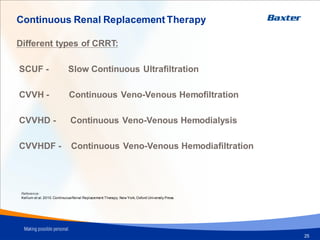
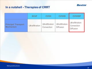
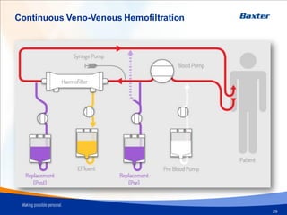
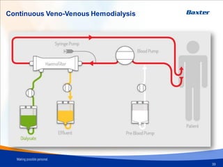
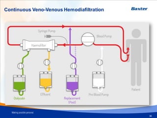
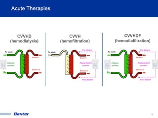
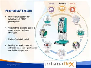
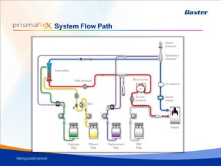
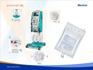
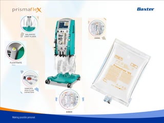
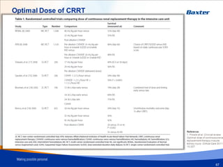
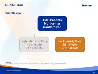
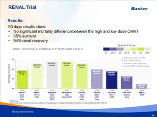
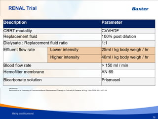
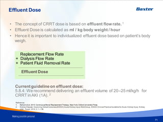
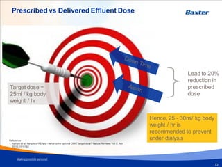
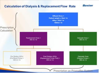
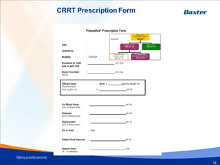
4. Continuous Renal Replacement Therapy
Different types of CRRT:
SCUF - Slow Continuous Ultrafiltration
CVVH - Continuous Veno-Venous Hemofiltration
CVVHD - Continuous Veno-Venous Hemodialysis
CVVHDF - Continuous Veno-Venous Hemodiafiltration
Reference:
Kellum et al. 2010.ContinuousRenal Replacement Therapy. New York, Oxford University Press.
25
5. In a nutshell - Therapies of CRRT
SCUF CVVH CVVHD CVVHDF
Principal Transport
Mechanism
Ultrafiltration
Ultrafiltration
Convection
Ultrafiltration
Diffusion
Ultrafiltration
Convection
Diffusion
26
7. Ultrafiltration
Ultrafiltration is the movement of fluid
through a semi-permeable membrane drive
by a pressure gradient
Ultrafiltration is the movement of fluid through a semi-
permeable membrane driven by a pressure gradient
Reference:
Kellum et al. 2010.
Continuous Renal
Replacement
Therapy. New
York, Oxford
University Press.
Ultrafiltration
28
9. Convection
Reference:
Kellum et al. 2010.
Continuous Renal
Replacement Therapy. New
York, Oxford University
Press.
Convection is the movement of solutes with fluid flow, also
known as solute drag. This movement of fluid is consequence
of transmembrane pressure (TMP) gradient.
Convection
30
10. Pre vs. Post Filter Dilution
Pre Dilution
Reduces risk of filter clotting
May prolonged filter life
Reduces effective clearance
Reference:
Kellum et al. 2010.
Continuous Renal
Replacement Therapy. New
York, Oxford University
Press.
11. Pre vs. Post Filter Dilution
Post Dilution
Increases risk of filter clotting.
Increased need of anticoagulant
No reduction of effective clearance
Reference:
Kellum et al. 2010.
Continuous Renal
Replacement Therapy. New
York, Oxford University
Press.
32
13. Diffusion
Reference:
Kellum et al. 2010.
Continuous Renal
Replacement Therapy. New
York, Oxford University
Press. Diffusion is the movement of solutes
from higher to lower concentration
Diffusion
34
16. Diffusion vs. Convection
CVVHD CVVH
The AN 69 membrane cut
off point is 30 kDaltons 1
Reference:
1. Vriese et al. Cytokine Removal during
Continuous Hemofiltration in Septic Patients.
J Am Soc Nephrol 10: 846–853, 1999
37
19. Prismaflex® System
• User friendly system for
individualized CRRT
prescriptions
• Versatility to facilitate use of a
wide range of treatment
strategies
• Patients’ safety in mind
• Leading in development of
extracorporeal blood purification
and fluid management
20. Why choose Prismaflex® system?
1. Slow, gentle and continuous
– Well tolerated by hemodynamically unstable patient
– Prevent further damage to kidney tissue
2. Removes small molecules (urea and creatinine) and larger molecules
(beta 2 microglobulin & inflammatory mediators)
3. More control of electrolytes & acid-base balance
4. Removes large amounts of fluid and waste products over time
– Allow other supportive measures, i.e. nutrition
Reference:
1. Bellomo, Ronco. Continoushemofiltration in theintensive care unit. Crit Care, 2000; 4(6) ): 339–345.
2. Schneider, et al. Choice of renal replacementtherapy modality and dialysisdependence after acute kidney injury: a systemati c review and meta-analysis.
Intensive Care Medicine. Published online: 27 February 2013
24. High-flow kidney-shaped
lumen design with 18% larger
arterial lumen, may ease
arterial pressure
Staggered double lumen tip
configuration free of side holes
may reduce risk of clotting1,2
Reference:
1. Huriaux L, et al. Hemodialysiscathetersin the intensive care unit, Anaesth Crit Care Pain Med. 2017;36:313-319.
2. Twardowski ZJ, et al. Side holesat the tip of chronic hemodialysiscathetersare harmful,J Vasc Access. 2001;2:8–16.
The optimal dialysis
catheter in ICU is the
Cycle C design with a
shotgun tip1
25.
26. Purpose
The main functional unit of the CRRT circuit, where blood is
processed for solute and/or fluid removal
49
27. Haemofilter
50
AN69 Membrane
Microporous asymmetric membranes, ie
Polysufone / PAES.
Symmetrical hydrogel structure. ie. AN69
Reference:
J. Chanard, et al. New insightsin dialysismembranebiocompatibility: relevance of adsorptionpropertiesand heparin binding.Nephrol Dial Transplant, 2003
PAES Membrane
CRRT (especiallyCVVH) with theAN 69 membrane, provide more adsorptive
capabilityas compared to other microporous asymmetric membranes; because
the entire breadth of the membrane is in contact with the blood compartment and
thus more accessible for adsorption.
Adsorption enables the removal of inflammatorycytokines.
CRRT Therapy Set – Prismaflex M Sets
28. Transport Mechanism - Adsorption
51
Adsorption is molecular adhering to surface or interior of a semi
permeable membrane
Reference:
Kellum et al. 2010.ContinuousRenal Replacement Therapy. New York, Oxford University Press.
30. 53
Heparin coating reduces membrane
thrombogenicity
PEI surface treatmentadsorbs
endotoxin
AN 69 base membrane adsorbs
cytokine and toxins whilst providing
continuous renal support. Cytokine
adsorption occurs throughout the
entire membrane thickness
oXiris The only set for 3-in-1 CRRT-Sepsis Management
33. Bicarbonate solution
57
CRRT Bicarbonate Solution
• Two-compartment bag in polyolefin material (PVC-free)
• Bicarbonate is separatedfrom calcium and magnesium
to prevent carbonate precipitation during storage
• 5 Litres per bag, 18-month shelf life
• Self-sealing Luer lock connector with valve and spike
connector
• Overwrap is made of severallayers of different materials
which are gas and water barriers
36. Regional Citrate Anticoagulation
Calcium ion will be chelated by
citrate – initialing anti
coagulation effect.
CRRT – Regional Citrate Anticoagulation
60
Citrate Calcium complexed will
be metabolized – ceasing anti
coagulation effect.
38. 62
Renal Replacement Therapy 1
(excretory function only)
Renal Support Therapy 2
Life threatening changes
Initiate emergently
• Immune modulation in sepsis
• Fluid balance • Volume balance in multi organ dysfunction / failure
• Electrolyte control • Nutritional support
• Acid–base regulation • Volume removal in refractory Congestive Heart Failure
Patient medical condition
Preference to initiate with
CRRT
• Alleviate ARDS induces respiratory acidosis
• Hemodynamically unstable
• Acute brain injury
• Generalized brain edema
• Increased intracranial pressure
Reference:
1. Kidney Disease: Improving Global Outcomes(KDIGO) Acute Kidney Injury WorkGroup. KDIGO Clinical PracticeGuidelinefor Acute Kidney Injury. Kidney
inter., Suppl. 2012; 2: 1–138.
2. Kellum et al. 2010.ContinuousRenal Replacement Therapy. New York, Oxford University Press.
Indications for Renal Replacement Therapy
39. Criteria for CRRT initiation
RENAL Trial
Reference:
BellomoR et al. Intensity of ContinuousRenal-Replacement Therapy in Critically Ill Patients. N Engl J Me 2009;361:1627-38
65
41. Optimal Dose of CRRT
Reference:
1. Prowle et al. Clinical review:
Optimal dose of continuousrena
replacement therapy inacute
kidney injury. Critical Care 2011,
15:207
67
42. RENAL Trial
68
Study Design
1508 Patients
Multicenter
Randomized
High Intensity Group
40 ml/kg/hr
747 patients
Low Intensity Group
25 ml/kg/hr
761 patients
Reference:
BellomoR et al. Intensity of ContinuousRenal-Replacement Therapy in Critically Ill Patients. N Engl J Me 2009;361:1627-38
Primary End Point: 90 days mortality
43. RENAL Trial
90 days results show:
• No significant mortality differencebetween the high and low dose CRRT
• 55% survival
• 94% renal recovery
Results:
Reference:
Bellomo R et al. Intensity of ContinuousRenal-Replacement Therapy in Critically Ill Patients. N Engl J Me 2009;361:1627-38
69
44. RENAL Trial
Description Parameter
CRRT modality CVVHDF
Replacement fluid 100% post dilution
Dialysate : Replacement fluid ratio 1:1
Effluent flow rate Lower intensity 25ml / kg body weigh / hr
Higher intensity 40ml / kg body weigh / hr
Blood flow rate > 150 ml / min
Hemofilter membrane AN 69
Bicarbonate solution Prismasol
Reference:
BellomoR et al. Intensity of ContinuousRenal-Replacement Therapy in Critically Ill Patients. N Engl J Me 2009;361:1627-38
70
45. Effluent Dose
71
• The concept of CRRT dose is based on effluent flow rate. 1
• Effluent Dose is calculated as ml / kg body weight / hour
• Hence it is important to individualized effluent dose based on patient’s body
weigh.
Replacement Flow Rate
+ Dialysis Flow Rate
+ Patient Fluid Removal Rate
Effluent Dose
Currentguidelineon effluent dose:
5.8.4: We recommend delivering an effluent volume of 20–25 ml/kg/h for
CRRT inAKI (1A). 2
Reference:
1. Kellum et al. 2010.ContinuousRenal Replacement Therapy. New York, Oxford University Press.
2. Kidney Disease: Improving Global Outcomes(KDIGO) Acute Kidney Injury WorkGroup. KDIGO Clinical PracticeGuidelinefor Acute Kidney Injury. Kidney
inter., Suppl. 2012; 2: 1–138.
46. Prescribed vs Delivered Effluent Dose
Target dose =
25ml / kg body
weight / hr
Hence, 25 - 30ml/ kg body
weight / hr is
recommended to prevent
under dialysis
Lead to 20%
reduction in
prescribed
dose
Reference:
1. Kellum et al. Resultsof RENAL—what isthe optimal CRRT target dose? Nature Reviews. Vol.6. Apr
2010: 191-192
72
47. Calculation of Dialysis & Replacement Flow Rate
73
Effluent Dose =
Patient weight x 30ml / hr
60kg x 30ml / hr
1800ml / hr
Replacement Dose =
900 ml / hr
Pre Dilution (50%)
(Pre Blood Pump) =
450 ml / hr
Post Dilution (50%)
(Replacement Pump Post) =
450 ml / hr
Dialysate Dose =
900 ml / hr
Dialysate Dose
(Dialysis Pump) =
900 ml / hr
Prescription
Calculation
Prescriptionon Prismaflex System