![Contactless Prox imity Smartcard s Classification based on Operating distance Close Coupling 0 – 1 cm [ISO 10536] Proximity 0 – 10 cm [ISO 14443] Type A Type B Type C Vicinity 0 – 1 m [ISO 15693] Type X Type Y 08/22/11 Anshuman Sinha <anshuman.sinha2@gmail.com>](https://image.slidesharecdn.com/typeavstypeb-1214860681717054-9/85/Contactless-Proximity-Smartcards-2-320.jpg)


![Type B - Anti-collision Packet Transmission and collision detection Method 1 - Slotted Aloha Method Method 2 – Probabilistic Slotted Aloha Method [Method 1] Time is divided into unit time for sending one packet. Packets will collide when multiple cards are in field until slots are allocated Transmit the packet, backoff and wait for the acknowledge If collision occurs wait for next slot marker to send the packet Packets involved in collision are lost, packet collision detected by CRC error(s) or timeouts 08/22/11 Anshuman Sinha <anshuman.sinha2@gmail.com>](https://image.slidesharecdn.com/typeavstypeb-1214860681717054-9/85/Contactless-Proximity-Smartcards-9-320.jpg)
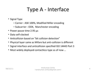
![Slotted Aloha [Method 1] Poisson distribution with number of channels in the field Throughput is underutilized when only one card is in the field Theoretical throughput maximum is 36.8% at 1 Requires queueing buffer for retransmission of packets 08/22/11 Anshuman Sinha <anshuman.sinha2@gmail.com> Offered Traffic Throughput 1](https://image.slidesharecdn.com/typeavstypeb-1214860681717054-9/85/Contactless-Proximity-Smartcards-10-320.jpg)
![Slotted Aloha [Method 1] REQB contains information on number of slots PCD selectively assigns a slot to the card Two levels of selection and rejection First level -> based on AFI and/or random number Second level -> based on CID in a slot Card agrees to speak on an assigned slot SLOT MARKER and ATTRIB command along with HLTB and ATQB assign the right slot to the card Once the card is in Active State the card responds only to the requests that are directed PUPI (Unique Card Identifier) is used as address of card while in Anti-collision process 08/22/11 Anshuman Sinha <anshuman.sinha2@gmail.com>](https://image.slidesharecdn.com/typeavstypeb-1214860681717054-9/85/Contactless-Proximity-Smartcards-11-320.jpg)
![Probabilistic [Method 2] First Level Selection by AFI Second Level Selection using R (Pseudo Random Number) IFD chooses AFI and N which are sent to card as part of REQB from the reader Only cards with matching AFI respond to the reader Tag or Card randomly generates R which is between 1 .. N (both inclusive) If R == 1, tag is selected to be in Active state (Probability of tag to generate R == 1 is 1/N) If R <> 1, tag doesn ’ t respond to the REQB During anti-collision process the card is identified by PUPI The reader will nominate a CID [0..16] to the tags that are Active. Reader can talk to 16 cards simultaneously if cards support CID 08/22/11 Anshuman Sinha <anshuman.sinha2@gmail.com>](https://image.slidesharecdn.com/typeavstypeb-1214860681717054-9/85/Contactless-Proximity-Smartcards-12-320.jpg)
![Type B Coding NRZ Code 08/22/11 Anshuman Sinha <anshuman.sinha2@gmail.com> 1 0 NRZ-L: [Non-Return-to-Zero-Level]: In NRZ-L encoding, the polarity of the signal changes only when the incoming signal changes from a one to a zero or from a zero to a one. NRZ-L method looks just like the NRZ method, except for the first input one data bit. This is because NRZ does not consider the first data bit to be a polarity change, where NRZ-L does.](https://image.slidesharecdn.com/typeavstypeb-1214860681717054-9/85/Contactless-Proximity-Smartcards-13-320.jpg)


The document details contactless proximity technology, specifically comparing Type A and Type B smart cards, focusing on their operational distances, data transfer rates, and anti-collision techniques. Type A uses a carrier frequency of 13.56 MHz with modified Miller encoding, while Type B employs NRZ-L encoding and requires a random number generator for its anti-collision process. The document also covers various standards and methods related to these technologies, including operational protocols and coding techniques.