
Recommended
More Related Content
What's hot
What's hot (20)
Similar to Construction of Steel Driven Pile for PMBP.pdf
Similar to Construction of Steel Driven Pile for PMBP.pdf (20)
Recently uploaded
Recently uploaded (20)
Construction of Steel Driven Pile for PMBP.pdf
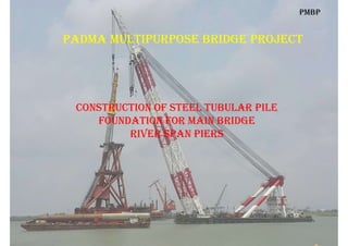
- 1. Padma multiPurPose Bridge Project construction of steel tuBular Pile foundation for main Bridge riVer sPan Piers PmBP
- 2. contents of Presentation PmBP 1. Bridge Alignment – Overview 2. Overview of Substructure Component 3. Feature of Steel Tubular Pile 4. Equipment for Steel Tubular Pile Driving 5. Fabrication of Steel Pile 6. Setting of Pile Position in River 7. Driving of Steel Tubular Pile 8. Installation of Cofferdam for Pile Cap 9. Concrete plugging , Base Grouting etc.
- 3. 1. Bridge alignment - oVerVieW PmBP
- 4. PmBP .
- 5. PmBP Bridge alignment Janjira End Mawa End Down Stream
- 6. 2. feature of main Bridge suBstructure PmBP
- 7. 1. Main Bridge Length : 6.15 Km 2. Nos. of Span and Span Length : 41 Nos.; 150m 3. Nos. of River Span Pier : 40 (P2 to P41) 4. Nos. of Transition Pier (Bank) : 2 (P1 & P42) 5. Nos. of Pile per Pier (River) : 6 for 18 & 7 for 22 Piers (Driven Steel Tubular Pile) 6. Total Nos. of Piles for River Span Pier : 6x18+7x22 = 262 7. Nos. of Piles per Transition Pier : 16 (Bored CIP Pile) 8. Total Nos. of Pile for Transition Piers : 2x16 = 32 PmBP salient feature of suBstructure/foundation
- 8. PmBP River Span Pier (40 Nos.) Pile Cap on 6 Nos. Steel Piles IN BRIDGE SUBSTRUCTURE- RIVER SPAN
- 9. PmBP Transition Pier- 2 Nos. Viaduct Piers TRANSITION PIER- END SPAN
- 10. riVer sPan Pier suBstructure PmBP Pier Shape : Rectangular-Hollow Pier Column Size : 8m x 4.8m Pile Cap Shape : Hexagonal Pile Cap Top : +6.5m PWD Pile Cap Bottom : +1.0m PWD Pile Cap Depth : 5.5m Max. Pier Ht. : 17.38m SHWL : 6.3m PWD
- 11. PmBP Plan VieW of Pile caP – riVer sPan Pile Cap Size : 18.66mx 16.16m Pile Cap Depth : 5.5m Pile Cap Bottom : +1.0m PWD Pile Spacing : 5.0m (at soffit)
- 12. PmBP 3d VieW of Pile grouP – riVer sPan Pier Pile Cap Size : 18.66mx 16.16m Pile Cap Depth : 5.5m Pile Spacing : 5.0m (at soffit)
- 13. PmBP 3d VieW of Pile grouP – riVer sPan Pier Pile Cap Size : 18.66mx 16.16m Pile Cap Depth : 5.5m Pile Spacing : 5.0m (at soffit)
- 14. 3. steel tuBular Pile for riVer sPan Pier PmBP
- 15. PmBP feature of steel tuBular Pile- riVer sPan Pier 1. Pile Type : Steel Tubular Rake Driven Pile 2. Pile Diameter : 3.0m ( OD) 3. Pile Wall Thickness : 60mm (Gen.); 80mm at Pile Shoe 4. Cut-off Level : +1.75m PWD (inside the pile cap) 5. Pile Toe Level : -122m;-114m PWD; -106m;-104m; -98m PWD 6. Pile Rake : 1 in 6 7. Pile Length (Rake) : Max. 125.45m; Min. 101.125m 8. Max. Design Axial Load : 87.6MN; 84.5 MN 9. Design Scour Level : -62m & -47m PWD (100 Year RP)
- 16. steel tuBular Pile – riVer sPan Pier PmBP • Conc. Plug Top : 15m • Comp. Sand Fill : Middle • Conc. Plug Bott. : 10m • Soil Plug : 5m Soil Plug Bott. Conc. Plug
- 17. PmBP 4. eQuiPments for steel Pile driVing
- 18. list of some Pile driVing eQuiPment PmBP 1. Hydraulic Hammer : MENCK –MHU 3500s; MHU2400s 2. Hydraulic Hammer : IHC- 3000; IHC-2000 3. Hydraulic Hammer : MHU – 550s 4. Vibrating Hammer : APE-600B 5. Floating Crane Barge : 1000 Ton 6. Floating Crane Barge : 500 ton 7. Floating Crane Barge : 200 Ton 8. Positioning Platform : Setting of Pier/Pile Position 9. Guide Frame : Setting of Pile Rake for Driving
- 19. Pile driVing Hammer : mHu 2400 PmBP MENCK HAMMER UNIT
- 20. Pile driVing Hammer : mHu 2400 PmBP 1. Max. Rated Energy : 2400 KJ 2. Min. Energy : 240 KJ 3. RAM Weight : 120 Ton 4. Hammer Weight : 244 Ton 5. Hammer Length : 16.20m 6. Origin : Germany
- 21. Pile driVing Hammer : mHu 2400 PmBP
- 22. Pile driVing Hammer : iHc 2000 PmBP 1. Max. Rated Energy : 2000 KJ 2. Min. Energy : 200 KJ 3. RAM Weight : 120 Ton 4. Hammer Weight : 310 Ton 5. Hammer Length : 22.26m 6. Origin : Netherland
- 23. Pile driVing Hammer : iHc 2000 PmBP
- 24. Hammer lifting crane: 1000 ton PmBP lifting crane : 500 ton
- 25. Hammer lifting crane: 1000 ton PmBP
- 26. construction seQuence of steel tuBular driVen Pile 1. Pile Fabrication/Manufacture at Workshop 2. Setting of Positioning Platform and Guide Frame in the River 3. Lifting & Setting of Pile (Bottom Section) on Guide Frame 4. Setting of Driving Hammer on Pile and complete the Driving of Bottom Sec 5. Partial Soil Removal from Bottom Section 6. Placing of Top Section on Driven Part and Splicing with FCAW (Welding) 7. Driving of Pile Top Section to Design Level and Repeat for Remaining Piles 8. Installation of Suspended Cofferdam on Pile Group and Sealing Bottom 9. Carryout Soil Removal, BG Hardware Installation, Concrete Plug, Base Grouting 10. Sand Filling, Rebar Installation and top Concrete Plugging. PmBP
- 27. PmBP 5. faBrication of steel tuBular Pile
- 28. Pile faBrication/manufacture from steel Plate Plate Origin : China Plate Size : 9.27mx3.22m Thickness : 60mm Grade : BS EN 10025 S355 PmBP Pre-Bending of Plate
- 29. Pile faBrication/manufacture from steel Plate PmBP
- 30. Pile faBrication/manufacture : Video PmBP
- 31. Pile faBrication/manufacture : Video PmBP
- 32. Pile faBrication/manufacture from steel Plate PmBP
- 34. Pile faBrication/manufacture : Welding PmBP
- 35. Pile faBrication/manufacture from steel Plate PmBP NDT(UT) for Welding Quality RE-Rolling of Pile Segment
- 36. Pile faBrication/manufacture : PmBP Straightness Check Diameter Check
- 38. Pile faBrication/manufacture : transPortation & storage PmBP Pile Storage in River Bottom Section : 71m Top Section : 48m
- 39. PmBP 6. setting of Pile Position in tHe riVer
- 40. Positioning Platform – Plan VieW PmBP
- 41. installation of Positioning Platform PmBP
- 44. comPlete Positioning Platform PmBP Positioning Pile Positioning Platform
- 46. guide frame on Barge PmBP Guide Frame Transporting
- 47. lifting of guide frame on Platform PmBP
- 48. setting of guide frame on Platform PmBP
- 49. setting of guide frame on Platform PmBP
- 50. lifting of Pile from Barge PmBP
- 51. Positioning of Pile on guide frame PmBP
- 52. setting of Pile to guide frame PmBP
- 53. 7. driVing of Pile By Hydraulic Hammer PmBP
- 55. PreParation of Hammer lifting PmBP
- 57. Placing of Hammer on Pile
- 58. setting of Hammer on Pile toP PmBP
- 59. driVing of steel Pile : Video PmBP
- 60. driVing of steel Pile : Video PmBP
- 61. driVing of steel Pile : Video PmBP
- 62. driVing of steel Pile : Video PmBP
- 63. sPlicing of Pile toP section PmBP
- 64. sPlicing of Pile toP section PmBP
- 65. driVing of Pile toP section PmBP
- 66. comPletion of driVing PmBP 1. Total Avg. Blow Count : 20000 Nos. 2. Blow Count for Top Sec. : 15000 Nos. 3. Max. Energy per Blow : 2400 KJ 4. Avg. Penetration/Blow : 1.75 mm 5. Driving Resistance (Blow/0.25m) : 150 6. Avg. Time for Full Driving : 20 hours 7. Bottom Sec. Driving Time : 6 hours 8. Top Section Driving Time : 14 hours nominal driVing record:
- 67. Pda test after driVing of steel Pile : Video PmBP
- 68. monitoring of Pile driVing: Video PmBP
- 69. monitoring of Pile driVing: Video PmBP
- 70. record sHeet of Pile driVing: PmBP
- 71. record sHeet of Pile driVing: PmBP
- 72. 8. susPended cofferdam for Pile caP PmBP
- 73. susPended cofferdam for Pile caP PmBP
- 75. cofferdam installation on Pile grouP PmBP
- 76. cofferdam Bottom sealing concrete PmBP
- 77. cofferdam Bottom after sealing PmBP
- 78. 9. soil remoVal and Bottom concrete Plug PmBP
- 79. arrangement for soil remoVal PmBP
- 80. drilling Bit for soil remoVal PmBP
- 81. rcd rig for soil remoVal PmBP
- 82. soil remoVal from Pile after driVing PmBP
- 83. soil remoVal from Pile after driVing PmBP
- 84. installation of Base grouting HardWare PmBP
- 85. casting of concrete Plug at Pile Bottom PmBP
- 86. Base grouting /Base Preloading of Pile PmBP
- 87. Base grouting /Base Preloading of Pile PmBP
- 88. monitoring of Base grouting Pressure at circuits PmBP
- 89. sand filling and comPaction inside Pile PmBP
- 90. concreting for toP Plug PmBP
- 91. PmBP making of Padma Bridge : sHort Video By mBec
- 92. PmBP making of Padma Bridge : sHort Video By kec
- 93. PmBP tHank you for attention