This document discusses prestressed concrete anchorages for large tainter gates used in dams. It provides background on the evolution of anchorage designs, from early steel designs to more modern prestressed concrete designs. It then describes the major design considerations for a prestressed concrete anchorage system, including prestressing the concrete girder transversely and longitudinally into the pier. Design of the longitudinal prestressing into the pier and transverse prestressing of the girder are discussed.
Various types of gates, their important componentsIEI GSC
Presentation on Various types of gates, their important components was done by Shri D.K.Mehta, Retired Chief Engineer, CWC, during One Day Seminar on Safety Inspection and O & M of gates for dams, canals etc conducted by Gujarat State Center of The Institution of Engineers (India) at Ahmedabad on July 3, 2015.
Video of this presentation can be seen on facebook as well as Youtube page of IEIGSC.
A water distribution system is a part of water supply network with components that carry potable water from a centralized treatment plant or wells to consumers to satisfy residential.
Concrete Gravity Dam Components
A gallery is a small passage in a dam for providing an access to the interior of the dam.
The gallery is usually rectangular in shape with its top and bottom either flat or semi circular.
For a gallery with its top and bottom flat, it is necessary that all the corners should be rounded. The width of gallery generally varies from 1.5 to 1.8 m. The height of the gallery in between 2.2 to 2.4 m, so that a person can easily walk inside it.
To provide drainage of the dam section.
2. To provide space for equipment required for drilling holes and grouting the hole to form a grout curtain in the foundation.
3. To provide space for header and return pipes for post cooling of concrete.
4. A gallery provide an access to the interior of the dam for inspection ard maintenance.
5. A Gallery also provides space for installing various instruments in the dam to study its structural behaviour.
6. A gallery can provide space for the mechanical and electrical equipment required for the operation of gates for spillways and outlets.
A shaft is a vertical opening provided in a dam. Shafts are required for locating headers of the post cooling system and for locating measuring devices.
Shafts are also required for the movement of elevators and the hoisting equipment. Sometimes shafts are constructed inclined to connect two galleries or the same gallery at two different elevations by a staircase or a lift arrangement.
A plumb line shaft is constructed at the maximum section of the dam to make observations of the deflection of the dam under loads.
A plumb bob is suspended by a wire fixed at the top of the shaft. As the dam deflects relative to the base, the plumb bob also moves by the same amount.
A stilling well shaft is a special shaft used to record fluctuations of the water level in the reservoir. The shaft is connected to the reservoir at a point below the minimum reservoir level.
There is a floating mechanism in the stilling well shaft which records fluctuations in the water level.
The spillway in a gravity dam is called overflow section. Spillway is provided to dispose of surplus water from the reservoir to the downstream.
Spillways are provided for all dams as a safety measure against overtopping and the consequent damages, and failure. spillway may be located either in the middle of the dam or at the end of the dam near abutment.
It must have adequate discharge capacity.
It must be hydraulically and structurally safe.
The surface of the spillway must be erosion resistant.
It should be provided with some device for the dissipation of excess energy
The portion of the gravity dam other than the spillway is a non-overflow section, a road is located on the non-overflow section of the dam.
At the one end of a gravity dam a power house is located. Water from the reservoir passes tnrough penstock and rotates the turbine provided at power elevations to produce electricity.
Water flowing over a spillway has a ver
This presentation includes introduction to run off river (ROR) plant and pumped storage plants, comparison between traditional and run off river plant, Classification of ROR Plants, Advantages and disadvantages of ROR Plants, Introduction to Pumped Storage Power (PSP) Plants, Classification of PSP, and Advantages and disadvantages of PSP
It contains detailed information about a Gravity Dam........it also conataims the information in brief & pictures giving a clear view of the Gravity Dams...........It also contains formulas with details of their terms.........
This is a presentation on various hydraulic structures and their uses and cross sections which will help a person to get acquainted with the most important hydraulic structures that are in use in this current world.
The SlideShare 101 is a quick start guide if you want to walk through the main features that the platform offers. This will keep getting updated as new features are launched.
The SlideShare 101 replaces the earlier "SlideShare Quick Tour".
Influence line diagram for model arch bridgekunalsahu9883
It mainly deals with the graphical representation of the influence line daigram of the reaction forces, Bending moment and displacement. The material and section properties are used as mention in design and modeling of the bridge. The modeling and analysis was of the “Lupu bridge” in the MIDAS Civil2014 software. This presentation provides a critical analysis of The Lupu Bridge in Shanghai.
In this ppt you will get all information regarding shaft sinking. Like what is permanent lining and temporary lining. How to decide shape of shaft, drilling blasting, support, lighting in shaft. Use of shaft and skips.
I was Visited a Site of Bajaj Engineers Project. We have seen their many problems arise in pile foundation and we think how this Problem Should Be Solved?
We Have Visited This Site And Decided To Do Project To Solve This Problem. Our Problem is pile foundation. According To Our Survey This Problem should be reduced by taking such steps towards this problem. We Make Survey On Whole Site And Find Out Problems And We Should Work On To Find Out Solution To Solve Problems
A bridge is the key element in a transportation system; it controls both the volume and weight of the traffic. Balance must be achieved between handling future traffic volume and loads and the cost of heavier and wider bridge structure. Economic Analysis and comparisons against competing alternatives is required as Bridges are the most expensive part of a road transportation network. Monetized & Non-Monetized Benefits that will accrue like time savings to road users, benefits to business activities (and to the economy in general) and salvage value benefits like Right-of-Way and substructure use need to be assessed as well.
7 Alternatives to Bullet Points in PowerPointAlvis Oh
So you tried all the ways to beautify your bullet points on your pitch deck but it just got way uglier. These points are supposed to be memorable and leave a lasting impression on your audience. With these tips, you'll no longer have to spend so much time thinking how you should present your pointers.
You could be a professional graphic designer and still make mistakes. There is always the possibility of human error. On the other hand if you’re not a designer, the chances of making some common graphic design mistakes are even higher. Because you don’t know what you don’t know. That’s where this blog comes in. To make your job easier and help you create better designs, we have put together a list of common graphic design mistakes that you need to avoid.
Transforming Brand Perception and Boosting Profitabilityaaryangarg12
In today's digital era, the dynamics of brand perception, consumer behavior, and profitability have been profoundly reshaped by the synergy of branding, social media, and website design. This research paper investigates the transformative power of these elements in influencing how individuals perceive brands and products and how this transformation can be harnessed to drive sales and profitability for businesses.
Through an exploration of brand psychology and consumer behavior, this study sheds light on the intricate ways in which effective branding strategies, strategic social media engagement, and user-centric website design contribute to altering consumers' perceptions. We delve into the principles that underlie successful brand transformations, examining how visual identity, messaging, and storytelling can captivate and resonate with target audiences.
Methodologically, this research employs a comprehensive approach, combining qualitative and quantitative analyses. Real-world case studies illustrate the impact of branding, social media campaigns, and website redesigns on consumer perception, sales figures, and profitability. We assess the various metrics, including brand awareness, customer engagement, conversion rates, and revenue growth, to measure the effectiveness of these strategies.
The results underscore the pivotal role of cohesive branding, social media influence, and website usability in shaping positive brand perceptions, influencing consumer decisions, and ultimately bolstering sales and profitability. This paper provides actionable insights and strategic recommendations for businesses seeking to leverage branding, social media, and website design as potent tools to enhance their market position and financial success.
Expert Accessory Dwelling Unit (ADU) Drafting ServicesResDraft
Whether you’re looking to create a guest house, a rental unit, or a private retreat, our experienced team will design a space that complements your existing home and maximizes your investment. We provide personalized, comprehensive expert accessory dwelling unit (ADU)drafting solutions tailored to your needs, ensuring a seamless process from concept to completion.
White wonder, Work developed by Eva TschoppMansi Shah
White Wonder by Eva Tschopp
A tale about our culture around the use of fertilizers and pesticides visiting small farms around Ahmedabad in Matar and Shilaj.
vernacular architecture in response to climate.pdf
Radial gates psc ancho
1. PROCEEDINGS PAPER
Prestressed Concrete Anchorages
for Large Tainter Gates
by Keith O. O'Donnell*
INTRODUCTION
The radial or tainter gate is the
most common type of spillway crest
gate used on large dam projects.
Because of the simplicity, light
weight, and low hoist requirements
of a tainter gate, economy has been
the basic reason for the trend to-
ward its increased usage. However,
this type of gate offers additional
advantages over other types, such
as permitting a very favorable
design from the standpoint of hy-
draulics, ease of service, and main-
tenance.
During the past decade, the Corps
of Engineers has designed tainter
gates for approximately 70 projects
including over 600 gates. Most of
these gates have been constructed
or are presently under construction.
Prior to that time, it was somewhat
unusual to design tainter gates in
excess of 40 ft. in height. It is now
not unusual to design 50-ft. wide
tainter gates subjected to a hydrau-
lic head of 60 ft. or more. For gates
of this size, the direct thrust from
hydraulic loading delivered to each
spillway pier is approximately six
million pounds. This load is trans-
mitted from the trunnion yokes to
*Structural Engineer
Office, Chief of Engineers
Washington, D.C.
52
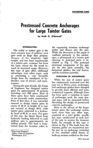
the supporting trunnion anchorage
girder and thence into the pier.
While the discussion in this paper is
confined primarily to the anchor-
ages, a photograph of a tainter gate
showing its principal parts is in-
cluded as Fig. I. The principal
structural components of the gate
are the skin plate assembly, the
horizontal girders, the end frames,
and the trunnion assembly.
EVOLUTION OF ANCHORAGES
While the size of tainter gates
has continuously increased over the
past ten or fifteen years, anchorages
and anchorage girders have changed
to provide more efficient and more
economical supports. Although there
has been quite a variation in types
of anchorages used, the more gen-
eral types will be presented before
discussing the design of prestressed
concrete anchorages.
Prior to the advent of the larger
tainter gates, the anchorage system
used, more than any other type,
consisted of a steel girder, usually
box type, cantilevered at each face
of the pier to receive the trunnion
loads. An example of this type is
shown in Fig. 2. The loads from the
trunnion girder are transmitted into
the pier by an anchorage consisting
of two standard rolled beams or
built-up sections welded to the trun-
PCI Journal
2. Fig. 1—Tainter Gate
BUTT WELDS FACE OF PIER
OF PIN
SLOT DOWNSTREAM FACE OF PIER e
FLANGE OF CROSS GIRDER
FOR TIE BEAM FLANGES
PLAN
UNBONDED OUTLINE OF PIER
OF PIN
Nf BEAM ._,•. ;e e' °•'. `^:
"' K
'°'`
APPR. CONSTR. JOINT
e
FOR ERECTION ONLY
TIE BEAM-ROLLED
OR BUILT-UP SECTION
SIDE ELEVATION
Fig. 2—Horizontal Tension Tie Anchorage
June 1965 53
3. nion girder and to an embedded
girder or grillage at the upstream
end. These tie beams are placed
with at least eight inches of con-
crete cover at the pier faces. The
embedded girder is designed to re-
ceive the entire load from the tie
beams in bearing. To allow free
movement or deformation of the tie
beams and prevent tension in the
pier concrete, the beams are un-
bonded or mechanically isolated
from the concrete for the entire
length by 1/2 inch of cork mastic.
For an intermediate pier with one
gate loaded and the adjacent gate
unloaded, the anchorage frame
formed by the trunnion girder and
the tie beams is subjected to severe
racking. In addition to the direct
tension in the tie beam nearest the
loaded gate, there are bending
stresses induced into the frame. This
type of anchorage has short vertical
beams embedded at the inner faces
of the tie beams to transmit both
the side thrust from the inclined
end frames and the vertical compo-
nent of trunnion reactions into the
pier. Sliding at the downstream
ends of the tie beams is allowed by
use of bronze plates.
Another type of anchorage that
had widespread use on the smaller
to the moderately sized gates is one
in which the trunnion loads are
E OF PIN
e ^°°,° STE EL PLATES BEAM
t
;TOP AND BOTTOM
_._ _
PLAN
€ OF PIN
^_ __^__ __ _ BACK OF
PIER°:OF PIN
OFTRU NNION
TAINTER GATE
vv '}
^, . ° Std'/O^,P Q^p1^' If
SPILLWAY CREST,°° ;°. S1E^^ W BEAM I I
• °8^ °° .:APPROXIMATE CONSTRUCTION JOINT STEEL PLATE .-
*' ANCHOR BOLTS ANCHOR BOLTS 1
SIDE ELEVATION
Fig. 3—Inclined Tension Tie Anchorage
54 PCI Journal
4. SYMMETRICAL ABOUT ( PIER
ii
l
FACE OF PIER
PLAN
II
II
p
j,.:.... A^ • ° ate.
a • IPRESTRESSING STEEL,
• a-:a
a
^p .p a ' 4 ELEVATION
•a
Fig. 4—Verticle Cantilevered Anchorage
transmitted to the concrete below
the pier rather than to the pier it-
self. This is shown in Fig. 3. In this
type, the anchor ties are inclined at
an angle with the horizontal large
enough to place the embedded
girder well below the level of the
spillway crest. Columns are pro-
vided under the trunnion girder to
take the vertical components of the
trunnion loads. The cork mastic is
also used in this case to isolate the
anchorage members from the con-
crete except at the embedded
girder and the column footings.
While this anchorage requires great-
er amount of structural steel than
the previous one, the reduction in
the amount of pier reinforcing steel
somewhat compensates for this.
While the above anchorages are
quite satisfactory structurally for
smaller gates, they are not suitable
for large gates. As the size of tainter
gates is increased, the problem of
providing an anchorage system be-
comes more complex. It is generally
economical to utilize the higher
strength structural steels in the de-
sign of larger tainter gates. How-
ever, their use is not feasible for the
anchorages because of the increase
in elastic deformation due to the
higher stresses, and because of in-
June 1965 55
5. crease in length of embedment re-
quired. Resulting elongations of the
tie beams would be excessive. The
natural solution is to prestress the
anchorage system into the pier. Pre-
stressing is preferred since it will
eliminate the relative movement
between the pier concrete and the
anchorage structure. A prestressed
anchorage system appears most es-
sential for large gates spanning be-
tween relatively narrow spillway
piers.
Two types of prestressed anchor-
age systems that have received
general usage consist of steel trun-
nion girders and post-tensioning
into the piers. The system shown in
Fig. 4 is one in which the trunnion
loads are taken by separate vertical
cantilever girders. While this type
of anchorage is not considered
economical, there is a construction
advantage in that each anchorage
can be aligned independently with-
out affecting adjacent gates. A more
conventional type consists of a
welded structural steel box girder,
similar to those used without pre-
stressing, cantilevered out on each
side of the pier to receive the
trunnion loads. The first designs in
the Corps of Engineers to incorpo-
rate post-tensioned anchorages were
for Markland and Greenup projects
on the Ohio River and were pre-
pared by the Seattle District.
For very large tainter gates in
which the total thrust anchored into
the pier amounts to more than, say
6,000,000 pounds, the amount of
structural steel involved in a trun-
nion girder becomes excessive. In
1961 a prestressed concrete anchor-
age was conceived and developed
for the spillway tainter gates on
Lower Monumental Lock and Dam
on the Snake River. The design of
Lower Monumental spillway gates
was also prepared by the Seattle
District. The gates on this project
are 50 ft. wide by 61 ft. high. The
girders are of high strength con-
crete, cast-in-place, post-tensioned,
square in cross-section, and abut
the downstream face of the pier.
Prestressing into the pier is similar
to that previously used for structural
steel girders.
MAJOR DESIGN CONSIDERATIONS
The prestressed concrete anchor-
age consists of two systems of post-
tensioned tendons; one for prestress-
ing the girder itself, and one for
prestressing into the pier. For dis-
cussion in this paper, the system of
prestressing of the girder will be
referred to as the "transverse" pre-
stressing and the prestressing into
the pier as "longitudinal." This
anchorage system is depicted in
Fig. 5.
A compressible filler is installed
over the central portion of the verti-
cal contact surface between the pier
and the girder. This gives a more
efficient arrangement by providing
a larger moment couple for the pre-
stressing forces and reducing the
bending in the girder. After pre-
stressing is completed, the prestress-
ing tendons are grouted and con-
crete caps are placed over the
exposed ends of both the transverse
and longitudinal tendons.
There are usually two major de-
sign conditions for the intermediate
piers: one in which both gates are
closed, and the other condition in
which one gate is closed with the
adjacent gate open. The latter con-
dition governs the design of the
longitudinal prestressing.
The longitudinal prestressing ele-
ments are arranged in two groups,
each group being placed as near the
pier face as practicable, allowing
about 9 inches of cover for the out-
side rows of tendons so that con-
56 PCI Journal
6. ADD GROUT CAP AFTER PRESTRESSING
IS COMPLETE. (TRANSVERSE
PRESTRESSING STEEL NOT SHOWN)
t PIER
TRUNNIONv YOKE NOT SHOWN THIS VIEW : GROATCAP ANCHOR PLATE
H___-- i
:';'ANCHOR PLATE
ELEVATION DOWNSTREAM ELEVATION
TRANSVERSE PRESTRESSING
STEEL
LONGITUDINAL.'•°,, • =1/2" COMPRESSIBLE°FILLER GROUT COVER
PRESTRESSING STEEL ,° `•, QPIER; ;°^,• _ NOTE: CONVENTIONAL REINFORCING°y
=I+ STEEL IN GIRDER AND PIER NOT
Yt SHOWN.
TRUNNION YOKE
PLAN GROUT COVER
Fig. 5—Prestressed Concrete Anchorage
ventional pier reinforcing steel may
be placed outside the prestressing
steel. The amount of prestressing
steel is determined assuming the
unbalanced condition of one gate
loaded with the adjacent gate un-
loaded.
While the bearing stress distribu-
tion is not exactly known, longitu-
dinal prestressing that will provide
an average residual bearing stress
between the girder and the pier
on the loaded side of about 20 per-
cent of the final prestress will gen-
erally be satisfactory. However, it
may be necessary to investigate the
interface pressures to assure that no
tension exists under unbalanced
loads.
The girder is considered a rigid
member with a straight-line varia-
tion in the stress distribution. How-
ever, for the girder design, the uni-
form stress distribution assumption
will be conservative.
Another consideration in the de-
sign of the longitudinal prestressing
into the pier is to unload the pre-
stressing load at the embedded end
gradually rather than abruptly on a
single vertical plane. This is ac-
complished by staggering the cutoffs
of tendons and will alleviate the
objectionable concentration of large
quantities of reinforcing steel that
would otherwise be required to con-
trol vertical tension cracks in the
pier concrete. Where practicable,
the gate trunnion assembly is posi-
tioned so that the vertical compo-
nent of thrust is negligible with the
gate closed and full pool. Theoreti-
cally, this places the trunnion at
about one-third the height of the
gate above the sill which permits
placing the pier prestressing ele-
ments horizontally.
A zone of high strength concrete
is incorporated into the pier for the
entire length and height of the pre-
stressing elements. Placing the pre-
stressing elements horizontally is a
construction convenience in that
fewer lifts of the high strength con-
June 1965 57
7. crete are required and also high
steel support frames for the down-
stream portion of the prestressing
elements are eliminated.
The design of the post-tensioning
elements into the pier can be ac-
complished without regard to the
trunnion girder design requirement.
After the longitudinal prestress has
been determined, all external loads
on the trunnion girder are known.
Design of the girder actually in-
volves two steps: (1) choice of the
geometry of the girder and (2)
the analysis of the trunnion girder
to determine the unit stresses and
establish the amount and arrange-
ment of transverse prestressing.
The facility of selecting a mem-
ber of proper section comes with
experience. Usually a concrete of
5,000 psi strength is required except
for larger gates which may require
higher strength concrete. The size
of the girder required is determined
by the magnitude of the bending,
shear (diagonal tension) and tor-
sion. Generally, the minimum width
of girder (vertical height) will be
established by the space required to
accommodate the longitudinal pre-
stress tendons. Maximum torsion
usually will occur in the girder when
the gate is partially raised and the
pool is at maximum level. When it
is practicable to position the trun-
nion yoke on the girder to minimize
the effects of torsion under the
maximum loading condition, the
combined shear, including torsion,
will not generally be critical for
other loading conditions. The flex-
ural stresses in most cases will be
considerably below those permitted
by specifications.
The ordinary beam theory or
straight-line distribution of flexural
stresses does not consider the effects
of the normal pressures from the
external loads and reactions at the
top and bottom edges of the beam.
For deep beams', however, these
effects are substantial and cause a
non-linear distribution of bending
stresses and the shear stress distribu-
tion is not considered parabolic.
Also, it has been shown in ordinary
shear investigation that even in
shallow beams the maximum princi-
paI tensile stress is exaggerated,
and that the critical section for in-
clined tension is not at the reaction
but some distance from the support.
The reason for this is that, near the
reaction, the values of the vertical
compressive stresses are large. An
analysis by the finite element meth-
od in plane stress analysis indicates
that the effects of the trunnion load
reduce the principal tension sub-
stantially.
For the reasons expressed in the
above paragraph, it is assumed that
the critical section for principal
tension is near the upstream edge
of the girder. This appears to be the
logical area for any cracks to de-
velop. With this assumption, the
principal stress obtained from com-
bining average shearing stress with
one normal stress is considered con-
servative, i.e., neglecting any com-
pressive stress caused by the trun-
nion reaction.
Limiting values for principal ten-
sile stress vary considerably. Based
upon working load, the limiting val-
ues of principal tension, as given in
T. Y. Lin's Design of Prestressed
Concrete Structures2 range from
about 0.015 f to 0.033 f , for beams
without web reinforcement. Consid-
ering ultimate load, the range is
from 0.045 f, to 0.08 f, without web
reinforcement, and to about 0.11 f
with web reinforcement. The codes
for prestressed concrete in the
United States make no reference to
58 PCI Journal
8. limiting values of working load prin-
cipal tension and generally the shear
design is based on ultimate strength.
A limiting principal tensile stress of
2 under working load is consid-
ered reasonable when no web rein-
forcement is provided. This is quite
comparable to the British Standard
Code of Practice. When web rein-
forcement is provided, a limiting
value of 3i is conservative. This
may serve as a guide; however, the
design should in the end be investi-
gated for ultimate strength and re-
inforcement provided accordingly.
For the small to moderate size
gates, it is practicable to limit the
computed principal tension to a val-
ue for which theoretically no web
reinforcement is necessary. However,
for the larger gates, the principal
tension, as computed often governs
the design, and it may not be prac-
ticable to limit the principal tension
to that in which no shear reinforce-
ment is required. While this method
of determining principal tension is
admittedly conservative, it is con-
sidered reasonable for design until
more is known on this subject. In
any case, it is considered prudent to
provide a nominal amount of web
reinforcement and this may be com-
puted by rule of thumb. The mini-
mum percent of web reinforcement
desirable is about 0.003 bs, in which
b is the width of girder and s the
spacing of web reinforcement.
The ultimate strength of girders
should be investigated both for
flexure and shear. The ultimate load
on the girder, based upon 1.8 times
the normal trunnion working load,
should not exceed the ultimate
flexural strength produced by the
following formula given in the ACI
Code:
Mu = 0 [A3 tau d (1-0.59 q)]
The principal tension in a pre-
stressed concrete member may in-
crease quite rapidly compared to the
unit shearing stress for an increase
in the external loading. For this rea-
son, it becomes necessary to inves-
tigate the principal tension under
ultimate shear load conditions. This
is accomplished by computing the
unit shear stress resulting from a
principal tension of 4V which is
considered the diagonal cracking
stress. The difference between the
shear value required for ultimate
strength and that for the shear crack-
ing load should be taken care of by
providing web reinforcement. This
is computed by the formula:
Av= T.-OV^)s0dt,
The areas of concrete beneath the
prestressing loads in both the girder
and the pier end anchorage zones
or end blocks are subject to tensile
stresses. The stress distribution is
rather complicated in the end an-
chorage zone of the pier with two
general areas of tension: (1) the
center of the section which is termed
the "bursting zone", (2) on the
sides and end surface called the
"tensile spalling zone". Guidance
for this type of behavior is dis-
cussed in Guyon's Prestressed Con-
crete. While there remains consider-
able latitude for the designer's
judgment, it is considered that gen-
erally conventional grid reinforce-
ment placed as near the surface as
practicable to take about 4 percent
of the total prestressing force will be
adequate in the spalling zone. To
prevent spalling of the concrete at
the corners of the pier, the outer
layer of reinforcement is welded to
angles embedded along the vertical
edges of the pier. Tensile stresses in
the bursting zone are evaluated by
Guyon and the ratio of the bursting
June 1965 59
9. tension to the prestressing force is
shown to be a maximum of about
0.18 for the typical pier load ar-
rangement. Reinforcement for these
stresses should be provided for a
distance in from the downstream
pier face of approximately one-half
the width of the pier. The theoreti-
cal stress pattern for these zones is
included in the above reference.
The actual final load on the pre-
stressing steel should not exceed 60
percent of the minimum ultimate
strength of the steel. The initial
tension on the steel, immediately
after seating of the anchorages,
should not exceed 70 percent of the
ultimate strength of the steel. The
computed losses in steel stress due
to elastic shortening of the concrete,
shrinkage, creep, and plastic flow
will be less for gate anchorage sys-
tems in massive piers than with
normal beam or slab prestressing.
Therefore, the initial prestress will
generally be somewhat below 70
percent of the ultimate strength to
assure that the final stress does not
exceed 60 percent.
To minimize integral action be-
tween the girder and the pier, the
girder is prestressed prior to longi-
tudinal prestressing.
ANALYSIS OF DESIGN
The steps in design procedure are:
1. Determine magnitude of the
longitudinal prestressing (into the
pier) required for the different
loading conditions which will com-
plete the applied loads for the
girder.
2. Determine the shear and mo-
ment diagrams for the appropriate
loading conditions.
3. Assume a girder cross section
and compute its properties.
4. Determine the magnitude and
arrangement of prestressing force to
provide compressive stresses to off-
60
set tensile stresses caused by bend-
ing moments and to limit the
principal tensile stresses.
5. Investigate stresses at both the
critical section for moment and the
critical section for shear with two
combinations of conditions, namely,
final prestress plus full design load
and initial prestress plus dead load
only.
6. Compute ultimate strength of
girder to see if it meets the require-
ments.
7. Design shear steel by ultimate
strength method.
8. Determine end block require-
ments.
Design of the longitudinal pre-
stressing is based upon an unbal-
anced loading condition of one gate
closed with the adjacent gate open,
see Fig. 6. To maintain a residual
bearing stress of 20 percent of the
final prestress, the prestress after
losses is
F=TXAX1.25
and the number of tendons required
in each prestress group is
F
N=
Its
where f t8 is the final prestress per
tendon (maximum value of 60 per-
cent of the ultimate strength). The
prestress force is then corrected for
the actual number of prestressing
tendons selected. The loading condi-
tions for the girder are now known
and the shear and moment diagrams
may be computed as indicated in
Fig. 6. Based on a trial section, the
girder can now be analyzed. The
width (vertical height) of the girder
is somewhat governed by the re-
quirement of the longitudinal pre-
stress force.
The girder prestressing arrange-
ment should be such that the down-
stream fibers of the girder under an
PC'I Journal
10. PRESTRESS FORCE
fflllUUth
d
dJ _____ _________
H
'no-
N
d
v ^
x 11
xW
3
W
°`
u
W oc
t,
a
N
a. 0 owe
eel w x >
INTERFACE BEARING
RTRUNNION THRUSTSTRESESS
I
T B/2 % (HORIZ.
^i 1 COMPONENT)F
1. A
SHEAR
MOMENT
Fig. 6—Load, Shear, and Moment in Girder
unloaded condition will not be in
tension due to prestressing and
dead load. It is suggested that a
minimum compression stress of 0 to
100 psi be maintained for the un-
loaded condition to insure compres-
sion across the entire section even
when the pool is below the level
of the gates. Fig. 7 indicates the
normal stress distribution on the
section of maximum shear due to
prestressing and moment at that
section. At the section of maximum
moment, no tension should result in
the upstream fibers under maximum
working load condition. At the sec-
tion of maximum shear, a fairly uni-
form distribution of normal stresses
across the section usually results
from bending and prestressing when
the prestressing is based on principal
stress limitations.
For the conditions in which tor-
sion is a consideration, the torsional
shear stress should be combined
with the direct shear stress. Where
it is required that torsional stress be
calculated, Bach's method may be
used as presented in Advanced
Mechanics of Materials4 by Seely
and Smith:
_9Mt
Sb 2 b d2
Sd = d Sb
b
June 1965 61
11. 100 psi f2 f4= f 2 + 100
HORIZ.
3 e
U t+—DEPTH
O PJ
LL
d
fl f2 f3= f 1 —f2
(a) (b) (c)
Fig. 7—Girder Stress Diagram
The principal tension may be ex-
pressed by:
ft=f2
/3— (f I2 +v2
V `
v bd
with a limitation of f t = 2 i/7 when
no design web reinforcement is pro-
vided and f t = 3 V7 with web rein-
forcement. The above equation is
solved for f 3 which is then expressed
by:
P Pec Mc
f3 = A — I--- I
where e<d/6
and finally the required girder pre-
stress force, P. is determined.
The above computations theoreti-
cally represent the condition at the
section of maximum shear stress. It
is now necessary to investigate the
stress conditions at the section of
maximum moment as indicated in
step 5 of the design procedure to
insure that allowable stresses are not
exceeded.
The ultimate flexural strength is
determined by the formula for M.
as previously stated. However, the
ratio of prestressing steel used should
be such that p f8;` does not exceed
fel
0.30. If this factor exceeds 0.3, then
the M. is computed by a different
formula and is given in the ACI
Code (Formula 26-8). The load fac-
tor of 1.8, as stated earlier in this
paper, is considered adequate for
this type of prestressed member
where the working loads are quite
definite. The shear steel, A, is then
determined based upon ultimate
shear strength. Maximum shear rein-
forcement should be provided as
previously discussed.
RESULTS OF MODEL TESTING
Because of its configuration, the
trunnion girder is beyond the range
of the usual beam or girder design.
Since the trunnion girder is canti-
levered at each side of the pier and
62 PCI Journal
12. the span is short, the behavior is
similar to that of a deep beam.
Stress distribution is quite complex
as a result of transverse prestressing
of the girder, longitudinal prestress-
ing into the pier, and gate loadings
which may be either symmetrical
or unsymmetrical. The interaction
between the girder and pier and
the compression in the beam be-
tween the yoke and the longitudinal
downstream anchor plate further
complicate the pattern of stress dis-
tribution and is quite indeterminate.
The applicability of the assump-
tions for conventional beam flexure
and shear to this type of structural
member was questioned. As a re-
sult, structural model tests were
performed to determine the struc-
tural strength and behavior, verify
the original design, and to provide
information for future designs. It is
beyond the scope of this paper to
discuss the model tests in detail,
and only a brief resume of the re-
sults is included.
The test program was performed
under the direction of Dr. Arthur R.
Anderson of Anderson, Birkeland,
Anderson & Mast of Tacoma for
the Seattle District of the Corps of
Engineers. The model tests included
nine beams which were tested to
failure. The prototype girders for
Lower Monumental tainter gate an-
chorages are 8 ft. by 8 ft. in cross
section by 23 ft. 2 in. long. A special
facility for testing one-fourth scale
models of the trunnion girders was
constructed with a block of concrete
to simulate the spillway pier. The
girder models were fastened to the
pier by post-tensioned high-tensile
strength steel rods. The girder
models were cast-in-place concrete
of 6,000 psi strength. A cross head
was built into the pier to jack
against for applying thrust (trun-
nion load) to the girder. The test
facility is shown in Fig. 8.
Various prestress combinations
were employed in the model testing.
The width of girder for the model
also was varied to determine the
effect of girder width on strain dis-
tribution in the concrete. Twenty-
four SR-4 type A-12 electric strain
gages were attached to the upper
surface of each model. Model No. 1
was cast on the pier which had the
surfaces of both the vertical face
Fig. 8—Model and Test Facility
June 1965 63
13. and the horizontal face sandblasted.
While this model was able to resist
up to 2.2 times the design load, it
was not possible to interpret the
strains measured because of the un-
known conditions resulting from
shear action between the model and
the pier. The other models tested
were cast by preventing bond on
the horizontal surface between the
girder and pier with the idea that
the model was free to deflect under
horizontal loads and that a stress
distribution conforming to that of a
beam subjected to bending could
be achieved.
The model tests revealed a very
complex behavior of the prestressed
concrete girder due to the interac-
tion of the trunnion girder and the
pier. As a result of this interaction,
the strains measured were not al-
ways linear with applied load which
made the interpretation of the data
difficult, Before the trunnion loads
are applied, the interface between
the girder and pier is under high
compression from the longitudinal
prestress, and as the load approaches
the prestress value, the pressure on
this face approaches zero. The
change in local concentrated stress
along the upstream face of the
girder is rather severe and a very
steep stress gradient results. Despite
the limitations of the strain meas-
urements in the girder model, they
are instructive in presenting the
behavior under load of a structure of
this type. The torsional effect from
vertical loads on the trunnion was
not serious. The crack patterns run
parallel to the hoop reinforcement
near the zone of maximum moment,
demonstrating that this reinforce-
ment contributes very little to the
ultimate shear strength of the gird-
ers. This was verified by one model
in which nearly all of the web rein-
forcement was omitted.
The model tests confirm that the
Lower Monumental girder design is
adequate and that the prestress in
the girder could be reduced some-
what and yet resist cracking at 1.5
design loads. In the model tests,
when a load 1.5 times the design
load was applied, the transverse
prestressing was reduced until crack-
ing occurred. At this point, the ten-
sion in the concrete on the upstream
face was approximately 1,000 psi,
computed by the straight-line meth-
od. With this reduced prestress force
applied for the design loads, a ten-
sion of 500 psi will exist based upon
a straight-line assumption.
Figs. 9 and 10 represent the results
of a computer program performed
by the Seattle District for the mod-
els. These theoretical analyses of
principal stresses are based on the
finite difference method and the fi-
nite element method. Fig. 11 gives a
comparison of flexural stresses based
upon theoretical analyses and
straight-line beam theory.
SUMMARY
Since the idea of prestressed an-
chorage systems was introduced, it
has been possible to utilize larger
tainter gates, in which the trunnion
Ioads on a single pier exceed six
million pounds, with far less em-
bedded anchorage metal than pre-
viously required and without a
substantial increase in pier size. The
use of the prestressed concrete trun-
nion girders has proven to be
economical. For the anchorage sys-
tem of the Lower Monumental
gates, the bid price indicates about
a 40 percent saving over a preced-
ing project having gates of similar
size but utilizing structural steel
trunnion girders. Studies and bids
on subsequent projects, including
smaller gates, also reflect a sub-
stantial saving though not generally
64 PCI Journal
14. sr
CD
I-
2" 11 s/4 113/4 '
2"
184 k I21" 21 184k
+653 I I x+653
F+980PSI+980PS1
PSI I.HOIE^ I PSI
F=310 k ►^5 y o ni"^' ^0 i 0 ^c ♦ $ F=310k
E=3.25"
t q5 45
E=3.25
X
GIRDER ,, so ^►o
R
l
so
o
^o
o '^i s y
R?SO lzso I ^000
+100PSI +100PSI
+1302PSI I +1302PSI
1 9" 10'/2 , 10'Y2^ 19"
280 kLY69'/s" 280k
MAXIMUM PRINCIPAL STRESS IMINIMUM PRINCIPAL STRESS
Fig. 9—Stress Countours•Finite Difference Method
C:,
Ut
15. 2" 11 3/4" 11 3/4" 2"
0
184 K+ o 184K
00
+653PSI 100 +653PSI
+980 PSI /,,_1E
+980 PSI
1000 ^{100 2$o 600
j / SOp ^`c y ^i X00 R tiho -ter ^R SOO R pt
c-F310 t ^R ^R ^ R >^ SCR y^ i R ^R R ^1R?SO ^IR F=310k
E=3.25" _^ pp x x dc) E=3.25"
GIRDER yR ^ ^R sow ^r ; } }^o „ 100 x ¢ GIRDER
'^ R1000 1^ + +^ I 4 ' y 11
R 750 DSO 0
?SO 1500 1000
100 PSI 100 PSI
+1302 PSI I I M+1302PSI
I
9" 10 1/2" 10 1/2"
280 K 1=69.1/2" 280K
MAXIMUM PRINCIPAL STRESS MINIMUM PRINCIPAL STRESS
rn
C)
0
Fig. 10—Stress Countours-Finite Element Method
16. 35 psi
29 psi
t!'? - 109 psi
O
// COMPRESSION
— TENSION
/ / • FINITE DIFFERENCE METHOD
i 0 FINITE ELEMENT METHOD
/ x STRAIGHT LINE METHOD
FINITE /
DIFFERENCE I ^/— STRAIGHT LINE
METHOD / METHOD
^ ^ 3
O
LL
FINITE ELEMENT METHOD
+1069/
pfd
+ 634 psi
+ 780 psi
COMPRESSION TENSION
^--TRANS. t GIRDER
Fig. 1 1—Comparison of Flexural Stress
June 1965 67
17. of this degree. The prestressed con-
crete anchorage is proposed for
several Corps of Engineers' projects.
Comparison of the results of
structural model tests, as well as
theoretical analyses by the finite ele-
ment method and finite difference
method confirm that the straight-
line theory for these structural mem-
bers is reasonable. While the model
tests demonstrate that a fairly high
flexural tensile stress, say about 400
psi, appears reasonable under work-
ing load conditions and would also
provide adequate ultimate strength,
it is not recommended that tension
be allowed in the design. This is in
accordance with the codes. While it
is recognized that the maximum
computed principal tension will be
somewhat greater than actually
exists, conservative design assump-
tions for this type of structural mem-
ber are recommended.
REFERENCES
1. Chow, L., Conway, H. D., and Winter,
George, "Stress in Deep Beams", Trans-
actions, ASCE Vol. 118, 1953.
2. Lin, T.Y., Design of Prestressed Con-
crete Structures, John Wiley and Sons,
Inc., New York.
3. Guyon, Y., Prestressed Concrete, Con-
tractors Record, Ltd., London and John
Wiley and Sons, Inc., New York.
4. Seely, F. B. and Smith, J. 0., Advanced
Mechanics of Materials, John Wiley
and Sons, Inc., New York.
Presented at the Tenth Annual Convention of the Pre-
stressed Concrete Institute, Washington, D.C. September 1964
68 PCI Journal