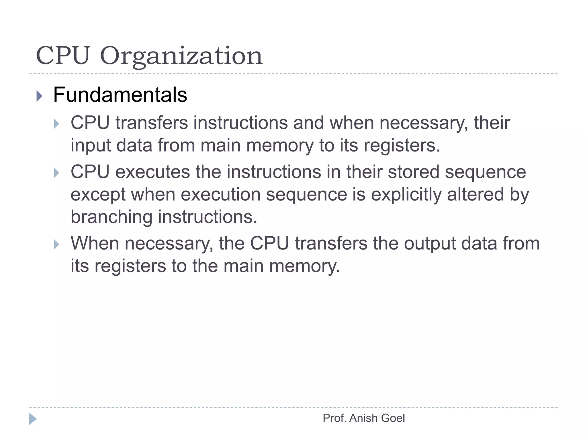
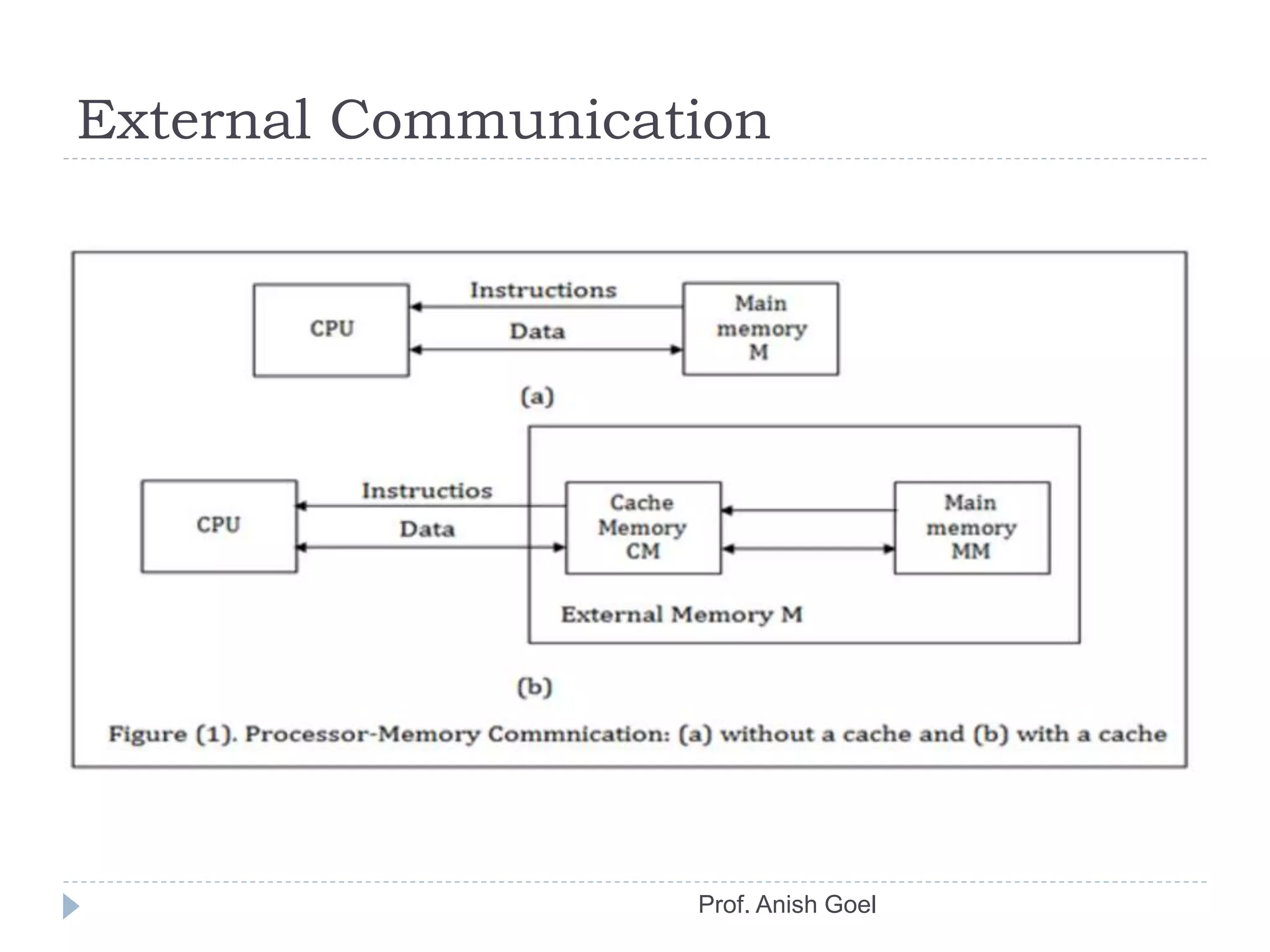
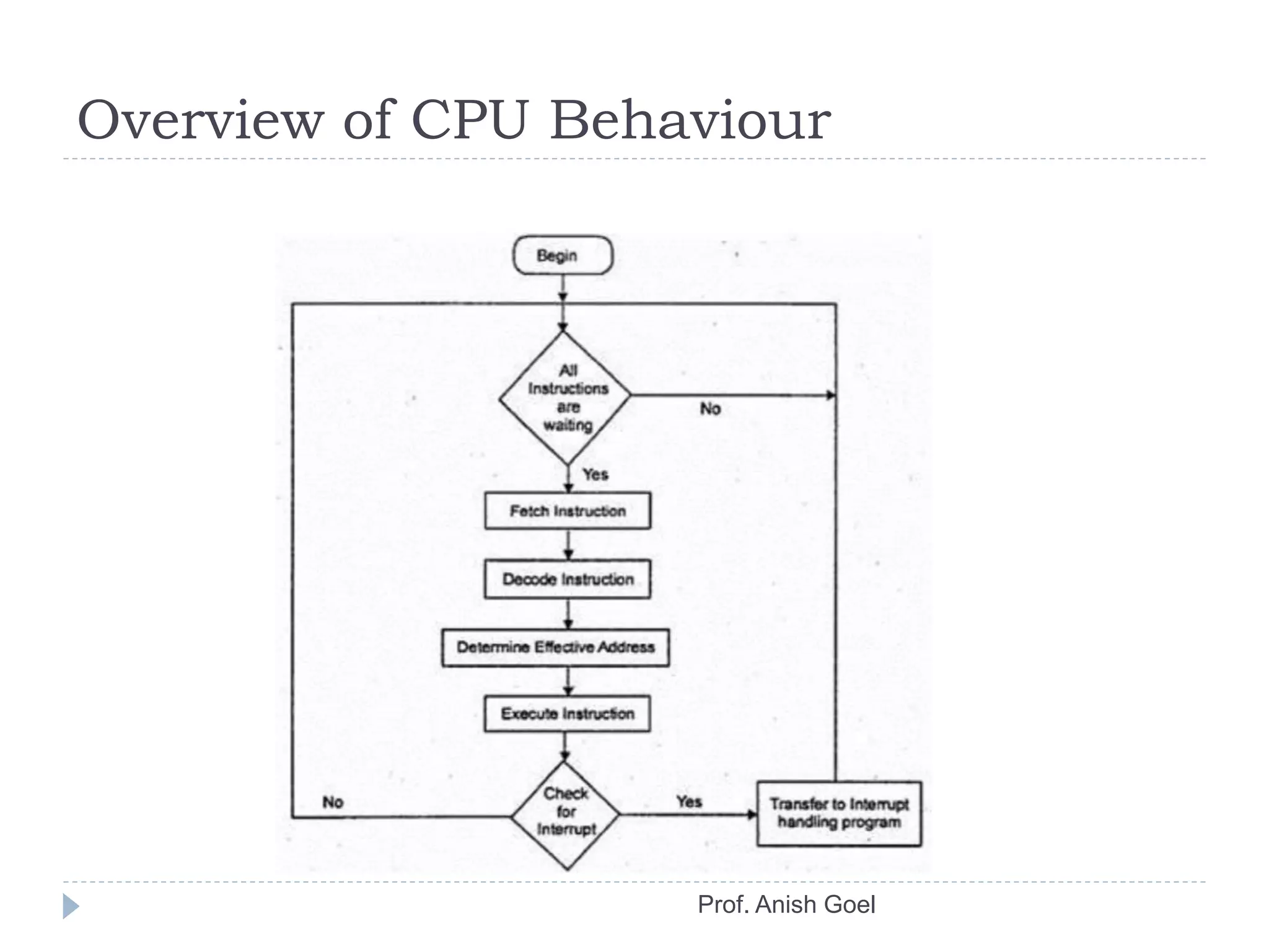
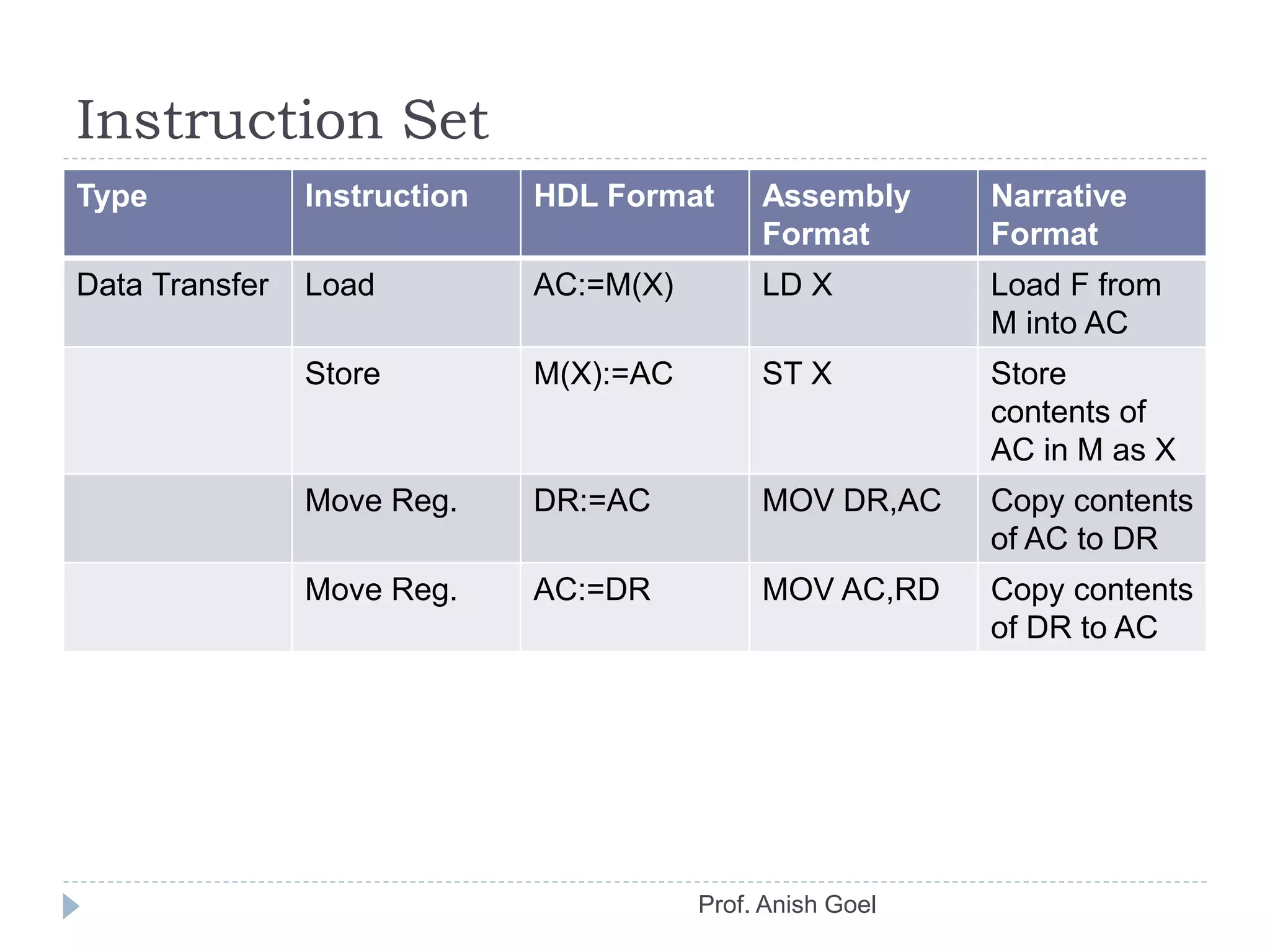
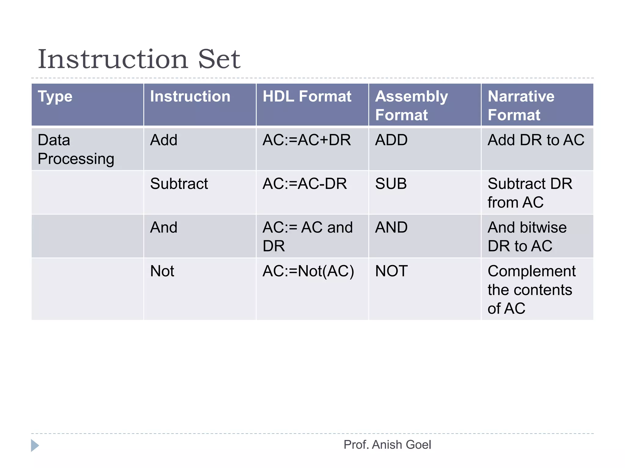
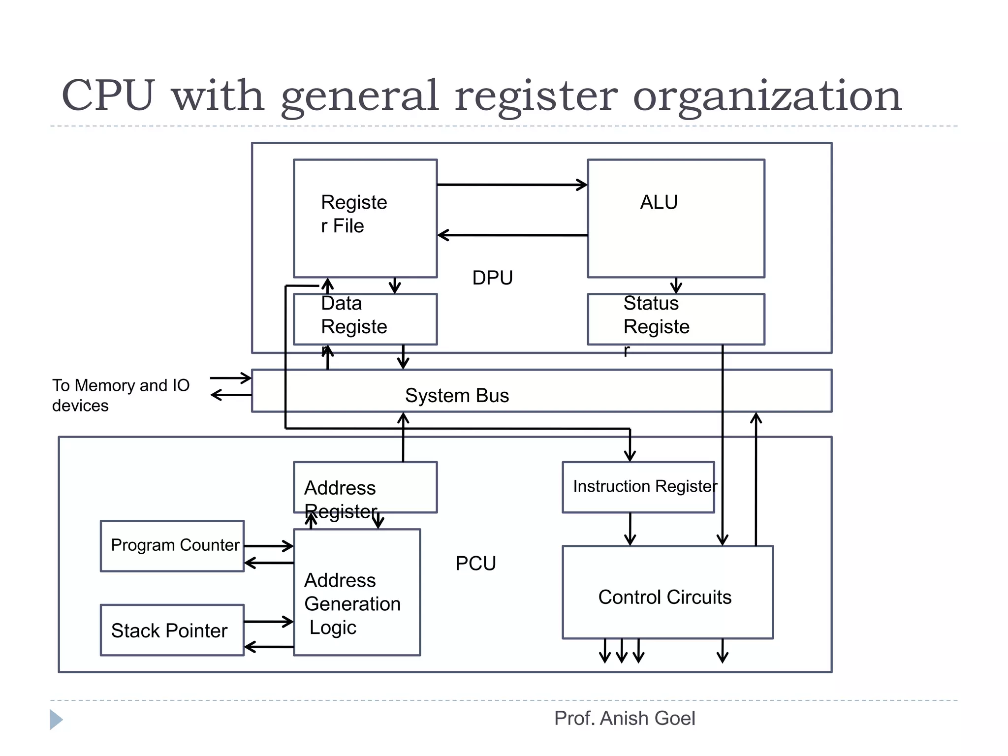
Processor Basics
Prof. Anish Goel
CPU Organization
 Fundamentals
 CPU transfers instructions and when necessary, their
input data from main memory to its registers.
 CPU executes the instructions in their stored sequence
except when execution sequence is explicitly altered by
branching instructions.
 When necessary, the CPU transfers the output data from
its registers to the main memory.
Prof. Anish Goel
External Communication
Prof. Anish Goel
User and Supervisor Modes
 The programs executed by GP computer falls into
two broad groups:
 User Programs
 Supervisor Programs.
 A user program is an application program.
 A supervisor program manages the various routine
aspects of the computer system on behalf of its
users.
 It’s a part of computers operating system.
 The CPU continuously switches between a user
program and a supervisor program.
 Interrupt is one such factor causing the switching
from one mode to another.
Prof. Anish Goel
Overview of CPU Behaviour
Prof. Anish Goel
Accumulator Based CPU
Instruction Decoder
IR AR PC
DR AC
System Bus
Arithmetic and Logic Unit
Data Processing
Unit
Program
control
unit
Control Signals
To Memory and IO
devices
Prof. Anish Goel
Instruction Set
Prof. Anish Goel
Type Instruction HDL Format Assembly
Format
Narrative
Format
Data Transfer Load AC:=M(X) LD X Load F from
M into AC
Store M(X):=AC ST X Store
contents of
AC in M as X
Move Reg. DR:=AC MOV DR,AC Copy contents
of AC to DR
Move Reg. AC:=DR MOV AC,RD Copy contents
of DR to AC
Instruction Set
Prof. Anish Goel
Type Instruction HDL Format Assembly
Format
Narrative
Format
Data
Processing
Add AC:=AC+DR ADD Add DR to AC
Subtract AC:=AC-DR SUB Subtract DR
from AC
And AC:= AC and
DR
AND And bitwise
DR to AC
Not AC:=Not(AC) NOT Complement
the contents
of AC
Instruction Set
Prof. Anish Goel
Type Instruction HDL Format Assembly
Format
Narrative
Format
Program
Control
Branch PC:=M(adr) BRA Adr Jump to
Instruction
with address
adr
Branch Zero If AC = 0 then
PC:= M(adr)
BZ adr Jump to
instruction
address adr if
AC = 0
Instructions
 X1 : = fi(X1,X2);
 X1 and X2 denotes CPU registers (AC, DR or PC)
 IR.AR := M(PC);
 IR := op, AR := adr
 Load store instructions
 AC := M(adr);
 M(adr) := AC;
Prof. Anish Goel
Additional Features
 Architecture extensions
 Multipurpose register set for storing data and addresses.
 Additional data, instruction, and address types.
 Register to indicate computation status.
 Program control stack.
 Pipelining.
Prof. Anish Goel
CPU with general register organization
Data
Registe
r
ALU
DPU
PCU
Registe
r File
Status
Registe
r
System Bus
Address
Register
Instruction Register
Address
Generation
Logic
Control Circuits
Program Counter
Stack Pointer
To Memory and IO
devices
Prof. Anish Goel
Instruction Pipeline
Prof. Anish Goel
ALU Design
Prof. Anish Goel
 The various circuits used to execute data-processing
instructions are usually combined in a single circuit
called ALU.
 The complexity of an ALU is determined by the way
in which its arithmetic instructions are realized.
 Simple ALUs that perform fixed-point addition and
subtraction as well as word-based logic operation
can be realized by combinational circuits.
 More extensive data processing and control logic is
necessary to implement floating point arithmetic in
hardware.
Combinational ALU: basic n-bit ALU
Prof. Anish Goel
N-bit
logic unit
N-bit
Adder-
Subtracte
r
2 way n-bit
multiplexer
X
Y
Data in
Data OutZ
Mode MCarry InSelect S
Flags

Computer Organization

  • 1.
  • 2.
    CPU Organization  Fundamentals CPU transfers instructions and when necessary, their input data from main memory to its registers.  CPU executes the instructions in their stored sequence except when execution sequence is explicitly altered by branching instructions.  When necessary, the CPU transfers the output data from its registers to the main memory. Prof. Anish Goel
  • 3.
  • 4.
    User and SupervisorModes  The programs executed by GP computer falls into two broad groups:  User Programs  Supervisor Programs.  A user program is an application program.  A supervisor program manages the various routine aspects of the computer system on behalf of its users.  It’s a part of computers operating system.  The CPU continuously switches between a user program and a supervisor program.  Interrupt is one such factor causing the switching from one mode to another. Prof. Anish Goel
  • 5.
    Overview of CPUBehaviour Prof. Anish Goel
  • 6.
    Accumulator Based CPU InstructionDecoder IR AR PC DR AC System Bus Arithmetic and Logic Unit Data Processing Unit Program control unit Control Signals To Memory and IO devices Prof. Anish Goel
  • 7.
    Instruction Set Prof. AnishGoel Type Instruction HDL Format Assembly Format Narrative Format Data Transfer Load AC:=M(X) LD X Load F from M into AC Store M(X):=AC ST X Store contents of AC in M as X Move Reg. DR:=AC MOV DR,AC Copy contents of AC to DR Move Reg. AC:=DR MOV AC,RD Copy contents of DR to AC
  • 8.
    Instruction Set Prof. AnishGoel Type Instruction HDL Format Assembly Format Narrative Format Data Processing Add AC:=AC+DR ADD Add DR to AC Subtract AC:=AC-DR SUB Subtract DR from AC And AC:= AC and DR AND And bitwise DR to AC Not AC:=Not(AC) NOT Complement the contents of AC
  • 9.
    Instruction Set Prof. AnishGoel Type Instruction HDL Format Assembly Format Narrative Format Program Control Branch PC:=M(adr) BRA Adr Jump to Instruction with address adr Branch Zero If AC = 0 then PC:= M(adr) BZ adr Jump to instruction address adr if AC = 0
  • 10.
    Instructions  X1 := fi(X1,X2);  X1 and X2 denotes CPU registers (AC, DR or PC)  IR.AR := M(PC);  IR := op, AR := adr  Load store instructions  AC := M(adr);  M(adr) := AC; Prof. Anish Goel
  • 11.
    Additional Features  Architectureextensions  Multipurpose register set for storing data and addresses.  Additional data, instruction, and address types.  Register to indicate computation status.  Program control stack.  Pipelining. Prof. Anish Goel
  • 12.
    CPU with generalregister organization Data Registe r ALU DPU PCU Registe r File Status Registe r System Bus Address Register Instruction Register Address Generation Logic Control Circuits Program Counter Stack Pointer To Memory and IO devices Prof. Anish Goel
  • 13.
  • 14.
    ALU Design Prof. AnishGoel  The various circuits used to execute data-processing instructions are usually combined in a single circuit called ALU.  The complexity of an ALU is determined by the way in which its arithmetic instructions are realized.  Simple ALUs that perform fixed-point addition and subtraction as well as word-based logic operation can be realized by combinational circuits.  More extensive data processing and control logic is necessary to implement floating point arithmetic in hardware.
  • 15.
    Combinational ALU: basicn-bit ALU Prof. Anish Goel N-bit logic unit N-bit Adder- Subtracte r 2 way n-bit multiplexer X Y Data in Data OutZ Mode MCarry InSelect S Flags