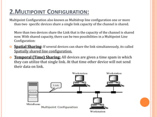
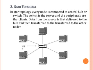
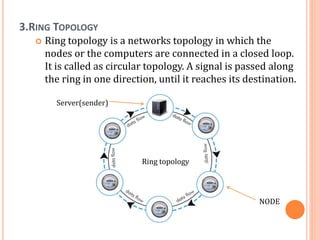
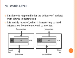
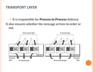
The document outlines fundamental concepts of computer networks, including data communication components, network types, and transmission modes. It highlights the distinctions between various network architectures like LANs, WANs, and MANs, as well as the significance of data processing methods. Key aspects such as performance, recovery, security, and the role of standards organizations in networking are also discussed.
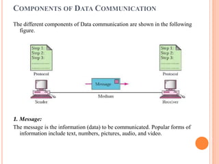


![How Big Brands are Taking Your Traffic in Alberta [Data Inside].pptx](https://cdn.slidesharecdn.com/ss_thumbnails/howbigbrandsaretakingyourtrafficinalbertadatainside-260123180142-42d276f3-thumbnail.jpg?width=640&height=640&fit=bounds)


