Components of Drip Irrigation System
•Download as PPTX, PDF•
0 likes•87 views

Water Delivery System. The bulk of all drip irrigation systems is comprised of a water delivery pathway made from either PVC pipe for underground delivery or polyethylene tubing for above ground delivery
Report
Share
Report
Share

Recommended
Ii air control valves
This document discusses pneumatic control systems and air control valves. It describes the main components of a pneumatic control system and categories of air control valves, including directional control valves, non-return valves, flow control valves, pressure control valves, and shut-off valves. It also covers the construction, operation, and sizing of directional control valves.
Control valve-sizing
This document provides information and equations for calculating the flow capacity (Cv) of control valves for liquid, gas, and two-phase flow. It defines Cv as the flow in gallons per minute through a valve with a one psi pressure drop. It describes how to calculate Cv for liquids and gases using factors like pressure recovery, critical pressure ratio, Reynolds number, and piping geometry. Guidelines are given for maximum recommended flow velocities depending on the type of fluid.
Valves used in industry
This document describes different types of valves and their functions, including:
- On-off valves like gate valves, plug valves, ball valves which are used to fully open or close flow.
- Throttling valves like globe valves and butterfly valves which are used to control the rate of flow.
- Check valves which allow flow in only one direction to prevent backflow.
- Pressure relief valves which open at a set pressure to release excess pressure and protect systems.
- Control valves and the components that are used in pneumatic pressure control systems.
High integrity pressure protection system ( HIPPS)
A high integrity pressure protection system is designed to prevent over-pressurization of a plant, such as a chemical plant or oil refinery
What is a control valve?
Control valves are instruments that control the flow of fluids through passages by varying the size of the passageway. They have a body, actuator, and positioner. The actuator directly controls the opening and closing of the valve body in response to signals from the positioner. Common actuator types include pneumatic, hydraulic, and electric. Pneumatic actuators typically use compressed air and a diaphragm to move the valve stem and vary the flow opening. Positioners receive control signals and ensure the actuator moves the valve to the desired position.
Basics of valves
This document describes different types of valves and their functions, including:
- On-off valves like gate valves, plug valves, ball valves which are used to fully open or close flow.
- Throttling valves like globe valves and butterfly valves which are used to control the rate of flow.
- Check valves which allow flow in only one direction to prevent backflow.
- Pressure relief valves which open at a set pressure to relieve excess pressure and protect systems.
- Control valves and the components that are used in pneumatic pressure control systems.
Control valve tutorials
The document contains a list of 91 topics related to control valves and instrumentation along with their respective website links. The topics cover various aspects of control valves including accessories, principles, types, parts, sizing, selection, installation, maintenance, failure modes, actuators, positioners and more. They provide information on control valves, control valve accessories, principles, types of valves like ball, butterfly, globe valves and their working. The topics also cover valve actuators, positioners, sizing, selection, installation, common problems and their solutions.
Axial regulator overview
This document describes axial flow regulators, which are compact inline pressure regulators. They use an external pilot regulator to control the opening and closing of a rubber sleeve, which acts as both a diaphragm and valve. The main components are the axial flow valve, inspirator block, and ZSC100 pilot. The axial flow valve uses a simple rubber sleeve that opens and closes based on pressure differences. The inspirator block contains a Venturi that reduces control pressure as flow increases to open the sleeve. The ZSC100 pilot maintains a spring-loaded control pressure. Axial flow regulators are versatile and can be used for pressure reduction, flow control, and relief applications.
Meeting w13 chapter 4 part 3
This document discusses various process control measurement techniques and final control elements. It describes common methods for measuring temperature, level, pressure, flow, and chemical analysis including thermocouples, RTDs, float systems, differential pressure, capacitive devices, ultrasonics, turbines, electromagnetic and Coriolis flow meters. Final control elements convert control signals into actions on process variables through signal conversion, actuators and control elements like valves.
pnuematic valve symbols
This document provides an overview of pneumatic symbols used in system diagrams and component identification. It includes standards for the symbols, basic shapes used to construct the symbols, common functional elements, flowlines and connections, conditioning components, pressure control devices, actuators including cylinders and valves, and details on valve symbol structure. The document is intended as a reference for understanding pneumatic circuit diagrams and component schematics.
CONTROL VALVES: CHARACTERISTICS, GAIN & TRANSFER FUNCTION
In this presentation are shown the main characteristics of control valves, with the descriptions of gain and transfer function.
Control valve Working and Types with Parts. Terms use in Control Valve
This document discusses control valves, including their classification, basic parts, types, and how they work. Control valves can regulate fluid flow and control process variables under controller commands. There are two main types: linear and rotary. The basic parts include a valve body, bonnet, plug, trim, and actuator. Actuators are either pneumatic or electric and convert control signals into valve stem movement. Positioners translate control signals into standardized signals for the actuator. Trim parts like the stem, seat and plug are exposed to the process flow.
Valve sizing reference
This document provides an overview of valve sizing and selection. It defines key terms like CV, FL, rangeability, cavitation, flashing, and compressible flow. It describes the sizing process which involves determining the required CV based on operating conditions and fluid properties, then selecting a valve with a rated CV that meets or exceeds the required CV. It also discusses how to address issues like cavitation, flashing, high velocities, and noise that may impact valve selection. Formulas are provided for calculating CV for liquid, gas, vapor and two-phase flow. Guidelines are given for selecting valves for applications involving cavitation, flashing, compressible flow or high velocities.
Monthly cheklist inspection
The monthly inspection checklist provides instructions for competent persons to complete a monthly inspection of any open excavations. It includes over 30 items across various building maintenance systems to check, including interior/exterior walls, windows, doors, floors, roofs, climate systems, heating systems, hydraulic systems, barriers, fences, and drinking water supply. Inspectors indicate for each item whether it is satisfactory or unsatisfactory and can include comments. The completed checklist must be signed by the inspector and supervisor and kept on record for the duration of the excavation.
Control valve
What Is A Control Valve
Process Control Terminology
Sliding-Stem Control Valve Terminology
Rotary-Shaft Control Valve Terminology
Control Valve Functions and Characteristics Terminology
Other Process Control Terminology
sliding stem control valve
ความรู้พื้นฐานระบบนิวเมติก
ความรู้พื้นฐานระบบนิวเมติก
สำหรับผู้เริ่มต้นศึกษาด้วยตัวเอง
และผู้ที่สนใจเกี่ยวกับระบบนิวเมติก
จัดทำโดย บริษัท Norgren (ผู้ผลิตและจำหน่ายอุปกรณ์นิวเมติก)
เผยแพร่โดย บริษัท นิวเมติก ดอทคอม จำกัด
http://xn--12c3bl6a3a1fd7g.com/category/products/%e0%b8%99%e0%b8%b4%e0%b8%a7%e0%b9%80%e0%b8%a1%e0%b8%95%e0%b8%b4%e0%b8%81%e0%b8%a2%e0%b8%b8%e0%b9%82%e0%b8%a3%e0%b8%9b/norgren%e2%84%a2/
Ease Control Valve Selection
While flow control is simple, selecting the right control valve is often complex due to the many types and options available. The key factors to consider when selecting a control valve are the process fluid, service requirements, and how the various valve types function. Control valves play a major role in process plant profitability and energy efficiency. Properly selecting a control valve based on its flow coefficient, trim, bonnet, and fail-safe position can significantly impact a project's costs and process control.
Twin Anti surge system
The document describes a twin antisurge protection system that uses two surge relief valves - a hot cycle valve and cool cycle valve. Each valve uses two surge relief plugs and a pilot to rapidly release overpressure within 100-150 milliseconds without overshoot or undershoot. This makes it the fastest, most efficient, and reliable surge protection system. It integrates all parts seamlessly and overcomes reliability, speed, and efficiency shortcomings of conventional systems through self-sensing tracking mechanisms and high reliability from system integration and redundancy.
General Control Valve Study
The document provides an overview of general control valves, including:
- Definitions of control valves and their functions
- The four main features of control valves: capacity, rangeability, characteristics, and pressure drop
- The three main types of flow characteristics: linear, equal percentage, and quick opening
- Potential issues like cavitation and flashing
- The components and construction of common control valve types like globe, ball, butterfly, and diaphragm valves
- Actuator types, bonnet designs, and other accessories
- Considerations for valve sizing, selection, and installation
Control valve
This document discusses different types of control valves, including globe valves, butterfly valves, ball valves, and gate valves. It describes control valve fundamentals and characteristics, such as Kv and Cv values that define flow capacity. Factors that affect flow capacity are discussed, along with potential issues like cavitation and solutions like anti-cavitation trim designs. Seat leakage classifications and plug designs are covered. In conclusion, control valves are final control elements in process systems and their characteristic curves define their control behavior.
Control valves
This document provides an overview of control valves, pressure regulators, and solenoid valves. It defines a control valve as a final control element used to manipulate flow for process control. It describes various types of control valves based on control action, flow characteristics, construction, and movement. Pressure regulating valves are designed to maintain a set pressure. Solenoid valves use an electric solenoid to switch ports and are commonly used as control accessories.
Control valve presentation
This document provides an overview of control valves, including applicable standards, types of control valves, leakage classes, characteristics, selection criteria, and noise and cavitation controls. It discusses control valve fundamentals like flow characterization using different cage designs, cavitation and flashing issues, and remedies. The document also summarizes Reliance Petroleum's control valve selection process and installed base of control valves from manufacturers like Fisher, ABB, and CCI.
01 General Control Valves Training.
Control Valves types, control valves characterstics, affects on control valves due to various process fluctuations or cavitations or flashing and remidies.The model datasheets also included.
Final Control Element
Final control elements are devices like valves and pumps that adjust the manipulated variable to control process parameters. Common parameters include pressure, flow, level, and temperature. Control valves have components like actuators, bodies, and trim. Actuators provide the force and include pneumatic, hydraulic, and electric types. Valves types are ball, butterfly, gate, and globe valves. Positioners maintain the correct valve position. Control valves can experience issues like leaks, sticking, or nonlinear flow. Troubleshooting addresses problems like deadband, overshoot, sizing errors, and nonlinear characteristics.
Dc valve
Directional control valves (DCVs) determine the path of fluid flow in hydraulic systems. There are several types of DCVs classified by fluid path, design characteristics, control method, and construction of internal moving parts. DCVs include check valves, shuttle valves, two-way valves, three-way valves, and four-way valves. DCVs can be actuated manually, mechanically, with a solenoid, or with a pilot signal. The simplest DCV is a check valve, which allows uni-directional flow. A poppet check valve uses a spring-loaded poppet to control flow direction, while a pilot-operated check valve uses a pilot signal to control flow in the
Process control valve engineering
The document provides an overview of control valve terminology, types, components, and standards. It defines key terms like hysteresis, dead band, linearity, rangeability, and accuracy. It describes the basic components of a control valve like the body, bonnet, trim, and actuator. It also lists several common international standards for control valves from organizations like ISA, ASME, ANSI, and API.
Control valve
Control valves are used to control process variables like pressure, flow, level and temperature. They work with a controller to form a control loop. The control valve manipulates the flow of process fluids like gas, steam, water or chemicals. It has a valve body, internal trim parts, an actuator and accessories. Control valves are classified based on their design as linear or rotary, and based on operation as throttling or on-off. Cavitation or flashing can occur if the downstream pressure reduces below the vapor pressure of the fluid.
شیرهای کنترلی دوستارگان
This document provides information about control valves, including:
1. Control valves are used to modify fluid flow rates in process systems and are typically operated automatically using air pressure.
2. Common types of control valves discussed include globe valves, diaphragm valves, and pinch valves.
3. Important parameters for selecting a control valve include its flow coefficient, pressure and temperature ratings, and cost considerations. Flow characteristics and applications of different valve types are also reviewed.
Air Valve Basic Training
Presentation explains all the basics about air valves including what are they for, what types are there, where do you use them, how big should they be, and many others.
Air Valve Basic Training
This presentation discusses the three main types of air valves, how to size them, and where to locate them on force mains and pipelines.
More Related Content
What's hot
Meeting w13 chapter 4 part 3
This document discusses various process control measurement techniques and final control elements. It describes common methods for measuring temperature, level, pressure, flow, and chemical analysis including thermocouples, RTDs, float systems, differential pressure, capacitive devices, ultrasonics, turbines, electromagnetic and Coriolis flow meters. Final control elements convert control signals into actions on process variables through signal conversion, actuators and control elements like valves.
pnuematic valve symbols
This document provides an overview of pneumatic symbols used in system diagrams and component identification. It includes standards for the symbols, basic shapes used to construct the symbols, common functional elements, flowlines and connections, conditioning components, pressure control devices, actuators including cylinders and valves, and details on valve symbol structure. The document is intended as a reference for understanding pneumatic circuit diagrams and component schematics.
CONTROL VALVES: CHARACTERISTICS, GAIN & TRANSFER FUNCTION
In this presentation are shown the main characteristics of control valves, with the descriptions of gain and transfer function.
Control valve Working and Types with Parts. Terms use in Control Valve
This document discusses control valves, including their classification, basic parts, types, and how they work. Control valves can regulate fluid flow and control process variables under controller commands. There are two main types: linear and rotary. The basic parts include a valve body, bonnet, plug, trim, and actuator. Actuators are either pneumatic or electric and convert control signals into valve stem movement. Positioners translate control signals into standardized signals for the actuator. Trim parts like the stem, seat and plug are exposed to the process flow.
Valve sizing reference
This document provides an overview of valve sizing and selection. It defines key terms like CV, FL, rangeability, cavitation, flashing, and compressible flow. It describes the sizing process which involves determining the required CV based on operating conditions and fluid properties, then selecting a valve with a rated CV that meets or exceeds the required CV. It also discusses how to address issues like cavitation, flashing, high velocities, and noise that may impact valve selection. Formulas are provided for calculating CV for liquid, gas, vapor and two-phase flow. Guidelines are given for selecting valves for applications involving cavitation, flashing, compressible flow or high velocities.
Monthly cheklist inspection
The monthly inspection checklist provides instructions for competent persons to complete a monthly inspection of any open excavations. It includes over 30 items across various building maintenance systems to check, including interior/exterior walls, windows, doors, floors, roofs, climate systems, heating systems, hydraulic systems, barriers, fences, and drinking water supply. Inspectors indicate for each item whether it is satisfactory or unsatisfactory and can include comments. The completed checklist must be signed by the inspector and supervisor and kept on record for the duration of the excavation.
Control valve
What Is A Control Valve
Process Control Terminology
Sliding-Stem Control Valve Terminology
Rotary-Shaft Control Valve Terminology
Control Valve Functions and Characteristics Terminology
Other Process Control Terminology
sliding stem control valve
ความรู้พื้นฐานระบบนิวเมติก
ความรู้พื้นฐานระบบนิวเมติก
สำหรับผู้เริ่มต้นศึกษาด้วยตัวเอง
และผู้ที่สนใจเกี่ยวกับระบบนิวเมติก
จัดทำโดย บริษัท Norgren (ผู้ผลิตและจำหน่ายอุปกรณ์นิวเมติก)
เผยแพร่โดย บริษัท นิวเมติก ดอทคอม จำกัด
http://xn--12c3bl6a3a1fd7g.com/category/products/%e0%b8%99%e0%b8%b4%e0%b8%a7%e0%b9%80%e0%b8%a1%e0%b8%95%e0%b8%b4%e0%b8%81%e0%b8%a2%e0%b8%b8%e0%b9%82%e0%b8%a3%e0%b8%9b/norgren%e2%84%a2/
Ease Control Valve Selection
While flow control is simple, selecting the right control valve is often complex due to the many types and options available. The key factors to consider when selecting a control valve are the process fluid, service requirements, and how the various valve types function. Control valves play a major role in process plant profitability and energy efficiency. Properly selecting a control valve based on its flow coefficient, trim, bonnet, and fail-safe position can significantly impact a project's costs and process control.
Twin Anti surge system
The document describes a twin antisurge protection system that uses two surge relief valves - a hot cycle valve and cool cycle valve. Each valve uses two surge relief plugs and a pilot to rapidly release overpressure within 100-150 milliseconds without overshoot or undershoot. This makes it the fastest, most efficient, and reliable surge protection system. It integrates all parts seamlessly and overcomes reliability, speed, and efficiency shortcomings of conventional systems through self-sensing tracking mechanisms and high reliability from system integration and redundancy.
General Control Valve Study
The document provides an overview of general control valves, including:
- Definitions of control valves and their functions
- The four main features of control valves: capacity, rangeability, characteristics, and pressure drop
- The three main types of flow characteristics: linear, equal percentage, and quick opening
- Potential issues like cavitation and flashing
- The components and construction of common control valve types like globe, ball, butterfly, and diaphragm valves
- Actuator types, bonnet designs, and other accessories
- Considerations for valve sizing, selection, and installation
Control valve
This document discusses different types of control valves, including globe valves, butterfly valves, ball valves, and gate valves. It describes control valve fundamentals and characteristics, such as Kv and Cv values that define flow capacity. Factors that affect flow capacity are discussed, along with potential issues like cavitation and solutions like anti-cavitation trim designs. Seat leakage classifications and plug designs are covered. In conclusion, control valves are final control elements in process systems and their characteristic curves define their control behavior.
Control valves
This document provides an overview of control valves, pressure regulators, and solenoid valves. It defines a control valve as a final control element used to manipulate flow for process control. It describes various types of control valves based on control action, flow characteristics, construction, and movement. Pressure regulating valves are designed to maintain a set pressure. Solenoid valves use an electric solenoid to switch ports and are commonly used as control accessories.
Control valve presentation
This document provides an overview of control valves, including applicable standards, types of control valves, leakage classes, characteristics, selection criteria, and noise and cavitation controls. It discusses control valve fundamentals like flow characterization using different cage designs, cavitation and flashing issues, and remedies. The document also summarizes Reliance Petroleum's control valve selection process and installed base of control valves from manufacturers like Fisher, ABB, and CCI.
01 General Control Valves Training.
Control Valves types, control valves characterstics, affects on control valves due to various process fluctuations or cavitations or flashing and remidies.The model datasheets also included.
Final Control Element
Final control elements are devices like valves and pumps that adjust the manipulated variable to control process parameters. Common parameters include pressure, flow, level, and temperature. Control valves have components like actuators, bodies, and trim. Actuators provide the force and include pneumatic, hydraulic, and electric types. Valves types are ball, butterfly, gate, and globe valves. Positioners maintain the correct valve position. Control valves can experience issues like leaks, sticking, or nonlinear flow. Troubleshooting addresses problems like deadband, overshoot, sizing errors, and nonlinear characteristics.
Dc valve
Directional control valves (DCVs) determine the path of fluid flow in hydraulic systems. There are several types of DCVs classified by fluid path, design characteristics, control method, and construction of internal moving parts. DCVs include check valves, shuttle valves, two-way valves, three-way valves, and four-way valves. DCVs can be actuated manually, mechanically, with a solenoid, or with a pilot signal. The simplest DCV is a check valve, which allows uni-directional flow. A poppet check valve uses a spring-loaded poppet to control flow direction, while a pilot-operated check valve uses a pilot signal to control flow in the
Process control valve engineering
The document provides an overview of control valve terminology, types, components, and standards. It defines key terms like hysteresis, dead band, linearity, rangeability, and accuracy. It describes the basic components of a control valve like the body, bonnet, trim, and actuator. It also lists several common international standards for control valves from organizations like ISA, ASME, ANSI, and API.
Control valve
Control valves are used to control process variables like pressure, flow, level and temperature. They work with a controller to form a control loop. The control valve manipulates the flow of process fluids like gas, steam, water or chemicals. It has a valve body, internal trim parts, an actuator and accessories. Control valves are classified based on their design as linear or rotary, and based on operation as throttling or on-off. Cavitation or flashing can occur if the downstream pressure reduces below the vapor pressure of the fluid.
شیرهای کنترلی دوستارگان
This document provides information about control valves, including:
1. Control valves are used to modify fluid flow rates in process systems and are typically operated automatically using air pressure.
2. Common types of control valves discussed include globe valves, diaphragm valves, and pinch valves.
3. Important parameters for selecting a control valve include its flow coefficient, pressure and temperature ratings, and cost considerations. Flow characteristics and applications of different valve types are also reviewed.
What's hot (20)
CONTROL VALVES: CHARACTERISTICS, GAIN & TRANSFER FUNCTION
CONTROL VALVES: CHARACTERISTICS, GAIN & TRANSFER FUNCTION
Control valve Working and Types with Parts. Terms use in Control Valve
Control valve Working and Types with Parts. Terms use in Control Valve
Similar to Components of Drip Irrigation System
Air Valve Basic Training
Presentation explains all the basics about air valves including what are they for, what types are there, where do you use them, how big should they be, and many others.
Air Valve Basic Training
This presentation discusses the three main types of air valves, how to size them, and where to locate them on force mains and pipelines.
Backflow Preventers
This document summarizes different types of backflow preventers used in irrigation systems. It describes atmospheric vacuum breakers, pressure vacuum breakers, reduced pressure backflow preventers, double check backflow preventers, and their applications based on flow rate and installation requirements. Selection of backflow preventers and sizing of mainlines and valves are discussed based on flow demands and allowable pressure losses.
Hydro test pump
This document provides information about hydro test pumps. It explains that hydro test pumps contain a pumping system and pressure measuring system to pump liquid into a closed system. The pumps can be hand operated or motor operated. Hydro test pumps are used to check for leaks in closed systems by filling them with liquid and monitoring pressure changes. Types of hydro test pumps include manually operated, motor operated, pneumatic, and multi-purpose test rigs. The main components and operation of a basic hand operated hydro test pump are described.
FUNDAMENTAL OF VALVE DESIGN
The document provides an overview of general control valves, including:
- Definitions of control valves and their functions
- Common features such as capacity, rangeability, characteristics, and pressure drop
- Types of flow characteristics including linear, equal percentage, and quick opening
- Potential issues like cavitation and flashing
- Examples of control valve classifications and constructions
- Considerations for actuators, bonnets, and accessories
The document serves as an introduction to key concepts for control valves.
Mechanical & pumping1
The document discusses plumbing systems, materials, and codes. It covers sanitary drainage systems, water supply sources and systems, common piping materials, fittings and valves, plumbing fixtures, and key plumbing codes and standards. It also discusses building water supply systems including main components, water pressure requirements, and distribution methods.
Automatic Recirculation Valve
This document discusses automatic recirculation valves (ARVs), which are multi-functional valves installed in centrifugal pump lines. ARVs ensure a minimum flow through pumps to prevent overheating and damage. They incorporate a check valve, bypass valve, and pressure control in one body. The document describes the operating principles of ARVs and provides an overview of common scenarios where ARVs protect centrifugal pumps. It also outlines SchuF Fetterolf's product ranges for ARVs, including standard and custom designs, and provides technical details.
Valves
Valves have different types and functions depending on the type of service. The main types are on-off valves like gate valves, plug valves, and ball valves which are used to start and stop flow. Throttling or regulating valves like globe valves and butterfly valves are used to control the flow rate. Check valves prevent backflow and include swing check valves, lift check valves, and ball check valves. Pressure relief valves like safety valves and relief valves are used to release excess pressure to protect systems. Control valves combined with actuators, controllers and sensors are used for automatic pressure control.
Drip irrigation kvg
The document discusses the key components of a drip irrigation system, including:
1. Filtration systems like hydrocyclone, screen, gravel, and disc filters to remove solid particles from water.
2. Mainlines, sub-mainlines, laterals, and emitters to distribute water.
3. Additional components like pressure regulators, backflow prevention, air/vacuum release valves, and controllers to regulate water flow and pressure.
4. The document provides details on the purpose and functioning of several common component types.
Hydraulic Ram Made from Standard Plumbing Parts
A hydraulic ram can be assembled from standard plumbing parts to pump water to higher elevations. The document provides instructions on assembling the ram from fittings like pipes, tees, valves, and a pressure tank. It also provides guidance on adjusting the ram for proper pumping by tweaking the swing check valve angle or drive pipe length.
3 valve shafts pneumatics and hydraulics
Control valves determine the direction and flow of fluid in hydraulic circuits. There are three main types: directional control valves, pressure control valves, and flow control valves. Directional control valves include check valves, shuttle valves, and multi-way valves which control fluid flow paths. Pressure control valves such as relief valves, sequence valves, and pressure reducing valves maintain safe pressure levels. Flow control valves regulate fluid flow rates and actuator speeds. Proper use of control valves is important for safe and efficient operation of hydraulic systems.
The Humble Check Valve
This document discusses the importance of properly selecting check valves for pumped systems to avoid issues like check valve slam. It notes that check valves are sometimes selected without considering their dynamic response under transient flow conditions. The key factors that affect a check valve's performance like mass, travel distance, and spring assistance are discussed. The document provides guidelines for selecting a check valve through modeling reverse flow velocities and decelerations and comparing valves based on dimensionless criteria. Different types of check valves are described and factors like installation location that can cause instability are covered. The importance of obtaining performance data from suppliers is also emphasized.
40+ TOP PIPING_INSTRUMENTATION INTERVIEW QUESTIONS.pdf
This document provides questions and answers related to piping and instrumentation topics. Some key points covered include:
- Instrument categories include flow, temperature, pressure, level, and density instruments.
- Block valves are used to isolate instruments like pressure indicators for maintenance and testing.
- Control valves are usually flanged for ease of installation and removal. Ball valves are used for slurry flows while butterfly valves are used for large clean flows with low pressure drop.
- Orifice plates and vortex meters are common flow measurement devices with straight run requirements before and after the device.
- Level can be measured directly via gauges or inferentially using methods like hydrostatic pressure, buoyancy, or floats.
- Common
Ryan Bushman Chemical & Backflow Prevention
This document discusses backflow prevention for irrigation systems. It defines backflow, cross connections, contamination and pollution. It discusses various plumbing codes and Utah's adoption of the 2006 International Plumbing Code. It outlines requirements for irrigation systems using secondary water only, drinking water only, or both. It describes chemical injection methods and required backflow prevention. Finally, it discusses different types of backflow prevention assemblies, proper installation, annual testing requirements, and potential irrigation hazards.
Production Optimization
The document provides information on production optimization through system analysis using nodal analysis. It discusses key components of the production system including reservoir fluid properties, inflow performance, tubing performance, and how to analyze the combined system. The objectives are to understand inflow, vertical lift, and combined performance. Nodal analysis is introduced as a technique to simulate fluid flow by breaking the system into nodes and ensuring pressure continuity. An example application optimizes a well's production rate by analyzing effects of tubing size, wellhead pressure, water cut, and skin on the combined inflow and outflow curves. The optimized design achieves a production rate of 114 MMscf/d with a 6.18" tubing and 2,000 psi
Production optimization
The document provides information on production optimization through system analysis using nodal analysis. It discusses key components of the production system including reservoir fluid properties, inflow performance, tubing performance, and how to analyze the combined system. The objectives are to understand inflow, vertical lift, and combined performance. Nodal analysis is introduced as a technique to simulate fluid flow by breaking the system into nodes and ensuring pressure continuity. An example application optimizes a well's production rate by analyzing effects of tubing size, wellhead pressure, water cut, and skin on the combined inflow and outflow curves. The optimized design achieves a production rate of 114 MMscf/d with a 6.18" tubing and 2,000 psi
Industrial valves
Valves are mechanical devices that regulate fluid flow by stopping, starting, throttling, and directing fluid movement. The main components of a valve include the body, bonnet, stem, disc, seat, and actuator. Valves are classified by their function as on/off, regulating, or protective. Common industrial valves include ball, gate, globe, butterfly, check, and diaphragm valves. Selection depends on the fluid, pressure, temperature, flow characteristics, and other criteria. Valve standards are set by organizations like API, ASME, and ANSI.
anaesthesia machine-140810030802-pptx.pptx
This document provides information about the functioning and components of an anesthesia machine. It discusses the pneumatic system including high, intermediate and low pressure sections. It describes the cylinders, regulators, flow meters, vaporizers and safety features. The key functions of the anesthesia machine are to provide oxygen, enable accurate gas mixture delivery and patient ventilation, and minimize risks to patients and staff. Safety features discussed include pin indexing systems, alarms and proportioning devices to prevent hypoxic gas delivery.
Hydraulic Ram Made from Standard Plumbing Parts - University of Georgia
This document provides instructions for assembling a hydraulic ram pump from standard plumbing parts. The assembly uses a swing check valve, spring loaded check valve, ball valves, unions, gauges and PVC or metal pipes. An inner tube is used as an air bladder in the pressure tank. The ram can be adjusted by changing the angle of the swing check valve or length of the drive pipe. Proper installation and startup is required to displace trapped air in the system.
Designer and operator manual dorot
This document contains a user manual for automatic control valves that includes the following sections:
- Section 1 provides information on basic valves including their operation, sizing guides for metal valves, details on plastic valves, and installation instructions.
- Section 2 covers automatic control valves in more detail including their design, operating pressures and velocities, media they can control, control options, and hydraulic performance.
- Section 3 includes operating instructions and a troubleshooting guide.
The manual provides technical specifications and guidelines for proper use of different types of automatic control valves for applications like irrigation, sewage, and industrial processes. It explains the valves' components, operation, pressure and flow characteristics.
Similar to Components of Drip Irrigation System (20)
40+ TOP PIPING_INSTRUMENTATION INTERVIEW QUESTIONS.pdf
40+ TOP PIPING_INSTRUMENTATION INTERVIEW QUESTIONS.pdf
Hydraulic Ram Made from Standard Plumbing Parts - University of Georgia
Hydraulic Ram Made from Standard Plumbing Parts - University of Georgia
Recently uploaded
RAT: Retrieval Augmented Thoughts Elicit Context-Aware Reasoning in Long-Hori...
RAT: Retrieval Augmented Thoughts Elicit Context-Aware Reasoning in Long-Horizon Generation
Understanding Inductive Bias in Machine Learning
This presentation explores the concept of inductive bias in machine learning. It explains how algorithms come with built-in assumptions and preferences that guide the learning process. You'll learn about the different types of inductive bias and how they can impact the performance and generalizability of machine learning models.
The presentation also covers the positive and negative aspects of inductive bias, along with strategies for mitigating potential drawbacks. We'll explore examples of how bias manifests in algorithms like neural networks and decision trees.
By understanding inductive bias, you can gain valuable insights into how machine learning models work and make informed decisions when building and deploying them.
22CYT12-Unit-V-E Waste and its Management.ppt
Introduction- e - waste – definition - sources of e-waste– hazardous substances in e-waste - effects of e-waste on environment and human health- need for e-waste management– e-waste handling rules - waste minimization techniques for managing e-waste – recycling of e-waste - disposal treatment methods of e- waste – mechanism of extraction of precious metal from leaching solution-global Scenario of E-waste – E-waste in India- case studies.
DfMAy 2024 - key insights and contributions
We have compiled the most important slides from each speaker's presentation. This year’s compilation, available for free, captures the key insights and contributions shared during the DfMAy 2024 conference.
Recycled Concrete Aggregate in Construction Part III
Using recycled concrete aggregates (RCA) for pavements is crucial to achieving sustainability. Implementing RCA for new pavement can minimize carbon footprint, conserve natural resources, reduce harmful emissions, and lower life cycle costs. Compared to natural aggregate (NA), RCA pavement has fewer comprehensive studies and sustainability assessments.
Technical Drawings introduction to drawing of prisms
Method of technical Drawing of prisms,and cylinders.
A SYSTEMATIC RISK ASSESSMENT APPROACH FOR SECURING THE SMART IRRIGATION SYSTEMS
The smart irrigation system represents an innovative approach to optimize water usage in agricultural and landscaping practices. The integration of cutting-edge technologies, including sensors, actuators, and data analysis, empowers this system to provide accurate monitoring and control of irrigation processes by leveraging real-time environmental conditions. The main objective of a smart irrigation system is to optimize water efficiency, minimize expenses, and foster the adoption of sustainable water management methods. This paper conducts a systematic risk assessment by exploring the key components/assets and their functionalities in the smart irrigation system. The crucial role of sensors in gathering data on soil moisture, weather patterns, and plant well-being is emphasized in this system. These sensors enable intelligent decision-making in irrigation scheduling and water distribution, leading to enhanced water efficiency and sustainable water management practices. Actuators enable automated control of irrigation devices, ensuring precise and targeted water delivery to plants. Additionally, the paper addresses the potential threat and vulnerabilities associated with smart irrigation systems. It discusses limitations of the system, such as power constraints and computational capabilities, and calculates the potential security risks. The paper suggests possible risk treatment methods for effective secure system operation. In conclusion, the paper emphasizes the significant benefits of implementing smart irrigation systems, including improved water conservation, increased crop yield, and reduced environmental impact. Additionally, based on the security analysis conducted, the paper recommends the implementation of countermeasures and security approaches to address vulnerabilities and ensure the integrity and reliability of the system. By incorporating these measures, smart irrigation technology can revolutionize water management practices in agriculture, promoting sustainability, resource efficiency, and safeguarding against potential security threats.
International Conference on NLP, Artificial Intelligence, Machine Learning an...
International Conference on NLP, Artificial Intelligence, Machine Learning and Applications (NLAIM 2024) offers a premier global platform for exchanging insights and findings in the theory, methodology, and applications of NLP, Artificial Intelligence, Machine Learning, and their applications. The conference seeks substantial contributions across all key domains of NLP, Artificial Intelligence, Machine Learning, and their practical applications, aiming to foster both theoretical advancements and real-world implementations. With a focus on facilitating collaboration between researchers and practitioners from academia and industry, the conference serves as a nexus for sharing the latest developments in the field.
Low power architecture of logic gates using adiabatic techniques
The growing significance of portable systems to limit power consumption in ultra-large-scale-integration chips of very high density, has recently led to rapid and inventive progresses in low-power design. The most effective technique is adiabatic logic circuit design in energy-efficient hardware. This paper presents two adiabatic approaches for the design of low power circuits, modified positive feedback adiabatic logic (modified PFAL) and the other is direct current diode based positive feedback adiabatic logic (DC-DB PFAL). Logic gates are the preliminary components in any digital circuit design. By improving the performance of basic gates, one can improvise the whole system performance. In this paper proposed circuit design of the low power architecture of OR/NOR, AND/NAND, and XOR/XNOR gates are presented using the said approaches and their results are analyzed for powerdissipation, delay, power-delay-product and rise time and compared with the other adiabatic techniques along with the conventional complementary metal oxide semiconductor (CMOS) designs reported in the literature. It has been found that the designs with DC-DB PFAL technique outperform with the percentage improvement of 65% for NOR gate and 7% for NAND gate and 34% for XNOR gate over the modified PFAL techniques at 10 MHz respectively.
Iron and Steel Technology Roadmap - Towards more sustainable steelmaking.pdf
Iron and Steel Technology towards Sustainable Steelmaking
A review on techniques and modelling methodologies used for checking electrom...
The proper function of the integrated circuit (IC) in an inhibiting electromagnetic environment has always been a serious concern throughout the decades of revolution in the world of electronics, from disjunct devices to today’s integrated circuit technology, where billions of transistors are combined on a single chip. The automotive industry and smart vehicles in particular, are confronting design issues such as being prone to electromagnetic interference (EMI). Electronic control devices calculate incorrect outputs because of EMI and sensors give misleading values which can prove fatal in case of automotives. In this paper, the authors have non exhaustively tried to review research work concerned with the investigation of EMI in ICs and prediction of this EMI using various modelling methodologies and measurement setups.
bank management system in java and mysql report1.pdf
truth is high but higher still is truth full living
Presentation of IEEE Slovenia CIS (Computational Intelligence Society) Chapte...
Presentation of IEEE Slovenia CIS (Computational Intelligence Society) Chapte...University of Maribor
Slides from talk presenting:
Aleš Zamuda: Presentation of IEEE Slovenia CIS (Computational Intelligence Society) Chapter and Networking.
Presentation at IcETRAN 2024 session:
"Inter-Society Networking Panel GRSS/MTT-S/CIS
Panel Session: Promoting Connection and Cooperation"
IEEE Slovenia GRSS
IEEE Serbia and Montenegro MTT-S
IEEE Slovenia CIS
11TH INTERNATIONAL CONFERENCE ON ELECTRICAL, ELECTRONIC AND COMPUTING ENGINEERING
3-6 June 2024, Niš, SerbiaRecently uploaded (20)
RAT: Retrieval Augmented Thoughts Elicit Context-Aware Reasoning in Long-Hori...
RAT: Retrieval Augmented Thoughts Elicit Context-Aware Reasoning in Long-Hori...
ACRP 4-09
Risk Assessment Method to Support Modification of Airfield Separat...
ACRP 4-09
Risk Assessment Method to Support Modification of Airfield Separat...
Recycled Concrete Aggregate in Construction Part III
Recycled Concrete Aggregate in Construction Part III
Technical Drawings introduction to drawing of prisms
Technical Drawings introduction to drawing of prisms
Manufacturing Process of molasses based distillery ppt.pptx
Manufacturing Process of molasses based distillery ppt.pptx
A SYSTEMATIC RISK ASSESSMENT APPROACH FOR SECURING THE SMART IRRIGATION SYSTEMS
A SYSTEMATIC RISK ASSESSMENT APPROACH FOR SECURING THE SMART IRRIGATION SYSTEMS
International Conference on NLP, Artificial Intelligence, Machine Learning an...
International Conference on NLP, Artificial Intelligence, Machine Learning an...
Low power architecture of logic gates using adiabatic techniques
Low power architecture of logic gates using adiabatic techniques
Iron and Steel Technology Roadmap - Towards more sustainable steelmaking.pdf
Iron and Steel Technology Roadmap - Towards more sustainable steelmaking.pdf
A review on techniques and modelling methodologies used for checking electrom...
A review on techniques and modelling methodologies used for checking electrom...
2. Operations Strategy in a Global Environment.ppt
2. Operations Strategy in a Global Environment.ppt
bank management system in java and mysql report1.pdf
bank management system in java and mysql report1.pdf
Presentation of IEEE Slovenia CIS (Computational Intelligence Society) Chapte...
Presentation of IEEE Slovenia CIS (Computational Intelligence Society) Chapte...
Components of Drip Irrigation System
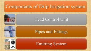
- 1. Components of Drip Irrigation system Head Control Unit Pipes and Fittings Emitting System
- 2. Head Control Unit Filtration System Primary Filter Secondary Filter Fertigation System Safety and Monitoring Devices NRV, PRV, ARV, Pressure Gauges, Flow Meter
- 3. Filtration System Primary Filters Gravel Filter Hydrocyclone Filter Screen Filter Disc Filter Secondary Filters
- 4. Fertigation System Fertilizer Tank Venturi Injector Injector Pump
- 5. Safety and Monitoring DevicesNon Return Valve Air Release Valve Pressure Release Valve Pressure Gauge Water Flow Meter
- 7. Pipe and Fittings PVC Pipe • Main Line • Sub-Main Line PVC Fitting HDPE Pipe and Fitting • Main Line • Sub-Main Line Control Valves
- 9. Emitting System Plain Laterals Emitter or Dripper Pressure Compensating Non Pressure Compensating Integrated Drip Line or Drip Tape Pressure Compensating Non Pressure Compensating
- 10. Emitting System Plain Lateral Dripper or Emitter Integrated Drip Line or Drip Tape