
Recommended
Recommended
More Related Content
What's hot
What's hot (20)
Similar to High integrity pressure protection system ( HIPPS)
Similar to High integrity pressure protection system ( HIPPS) (20)
Recently uploaded
Recently uploaded (20)
High integrity pressure protection system ( HIPPS)
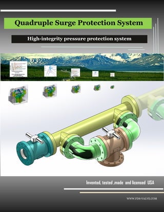
- 1. Quadruple Surge Protection System WWW.FDS-VALVE.COM Invented, tested ,made and licensed USA High-integrity pressure protection system
- 2. Design Features Quadruple pressure surge protection system WWW.FDS-VALVE.COM 1-1 The FDS surge protection sys- tem includes Isolating , relief units and are used for both gas or liquid surge protection applications with speed of 150– 350 millisecond either open or closed, it is the fastest and most reliably operation in the world . The simple system was developed to fully integrate all parts as one unit and overcome shorting comings of conventional HIPPS and surge relief protection systems in term of reliability and speed and seamless connection , it has four 21 first century break- through technologies (1) liquid self feedback and actuation mechanism without external power (2) gas self feedback and actuation mechanism without external power , no gas con- sumption (3) High reliability , 4 re- dundancies for the system or 2 for each subsystem , each function unit has one moving part (4) High versatili- ty , it can work at gas or liquid and with dirty liquid , the temperature gra- dient between –450 to 1100 F Pressure Class 150-1500 Pipe Size 2”-24” Temperature -450 F to 1100 F Leakage Class : V- VI Fluid content : Gas, dirty fluid Operation speed 150- 250 millisecond Operation type: On-off Redundancies 4 External power Not required Gas consumption No U.S Regulation DOT Part 195, 195.428 Thermal bearing bushing Outlet , normal pressure zone Isolating subsystem Two Protected Barriers Universal body Surge high pressure zone Dual Wedge joint Buckling stop pin Relief subsystem Two protected gates -450 F Inlet Two normal closed in- dependent plugs Fail –open Two normal open independent plugs Fail -closed Relief outlet Low pressure Zone
- 3. The differential relief mechanism is designed to separate a single pressure relief process to (1) sensing/ tracking , (2) pres- sure differential amplifying and (3) actuation, this mechanism greatly in- crease the sensibility with a very small shutter at stable static pressure zone , and rapid increasing differ- ential pressures between inlet and internal plug ,so the plug would move at the highest pressure difference and speed. Sensing /tracking , the fluid path with black arrows from Zone 1 ,Zone 2, Zone3 , P1 , P2 ,P2 , when a set pressure Ps > P1, the plug stays at a closed stage, no surge pressure and the pressures , P1 = P2 = P3 , When p1 =P2=P3 > Ps , the shutter would move back and open sens- ing port . Pressure differential ampli- fying , when the shutter opens and creates flow fluid as well as the pres- sure drop , since the differ- ential tube is small and long and generates large pres- sure drop between P1 and P2, P3 = 0 , the large pres- sure differences generate Full piston actuation , un- like conventional actuation , the fluid release go through three paths (1) sensing port , link ports and inlet port , since the cap has no axial holes with full piston effect and move the plug the fastest speech Design Features BN Relief subsystem —Liquid self releasing mechanism (1) 1-2 There is a surge pressures when P1 =p2 = P3 > Ps, the shutter moves back and open , p3 =0 , the flow fluid go through three zones and the differential tube and generates a big pressure drop between P1 and P2 No surge pressure when P1 < Ps a set pressure at Zone 3 , Pressures at three zones P1=P2=P3, the plug stay at the closed position , Offset angle 68 F Lock ring The pilot is closed Sensing fluid zone , local Pressure p3 =P2=P1 Shutter spring against the shutter for sensing P3 Disc Body Relief pilot Cap with Link ports Inlet fluid Zone P1 Sensing port Plug fluid Zone P2 Plug chamber Pressure differential Tube Plugs at closed positions Relief outlet Sensing fluid zone P3 = 0 or < P2 and P1 Shutter move back and open The Pilot is open Relief port
- 4. The Fast surge pressure relief is depended on two factors (1) actuating force on the plug and (2) relief flow rate out the system Actuating force generates speed as Newtown second law states F= a * M , F = force , a = acceleration , so the bigger the pressure difference and less mass of plug , the faster speed of plug , the plugs move as the same direction of flow , less noise and vibration Relief flow rate , speed of relief volume , as the Ber- noulli equation states , the surge is caused by reduc- ing the velocity or height if we reverse the surge of pressure process by in- creasing the velocity ,or negative heights the pres- sure would drop, Two redundant inlet ports in an opposite direction increase flow rate capaci- ty , speed and cancel out reaction force on the body and reduce cavitation and erosion due to interaction of two fluid streams not interact between solid body and fluid , the relief fluid includes three paths in the shortest distance Dirty fluid capability, the plug chamber is designed to collect solid particles and prevent the dirties from entering sensing port . Check valve is designed to restrict income flow and educe the speed of closing and enlarge outgoing flow speed. Design Features BN Relief subsystem —Liquid self releasing mechanism (2) 1-3 Open to large outgoing flow re- lief under different pressure be- tween P1 and P2 Offset angle 68 F Outgoing flow Disc Body Relief pilot Cap with Link ports Inlet fluid Zone P1 Sensing port Plug fluid Zone P2 Plug chamber Outgoing flows Plugs move to open Relief outlet P3 High velocity stream at the center area and reduce the wall damage due to erosion and cavitation Sensing point at the blue stable pressures zone Flow direction Check valve
- 5. The gas-powered releasing mechanism has the fastest response time about 150 millisecond , it combined the sensing/track, pressure different amplifying and actuation as one, it has two benefits , speech and simple structure The regulated gas in plug is to sense pressure of incoming fluid pressure , since the gas is compressi- ble as the Pi pressure in- crease and over the set pressure and would push the plug to open position, while as the Pi reduce , the plug would move back smoothly ,. All gases are effected by three factors, Tempera- ture , volume and pressure , PV= n RT, the pre set pres- sure is very important for the relief function and must be kept the same all time, so self relief regulator is used to keep the constant pressure, but waste gas in the conventional system Thermal chamber is de- signed to control pressure by using liquid or heater to change the temperature like subsea or day and night temperature change Relief Pilot is designed to release over pressure inter- nally as a redundancy to regulate the pressure Gas accumulator is used with thermal chamber and pilot thermal chamber for fully regulating the gas tem- perature No gas consumption Design Features CN Relief subsystem —Gas powered releasing Mechanism 1-4 Regulated gas as a set pres- sure Ps Pre set Spring against Gas pressure Offset angle Relief pilot 68 F Lock ring Bottled gas Disc Body Relief Pilot Thermal chamber to regulate the gas tem- perature to increase or decrease pressure Inlet fluid gas or liquid P1 Pilot inlet connect to gas source and accumulator Gas Accumulators Pressurized Gas port
- 6. Why redundancy In 1999, a pressure relief valve failed on a 16-inch gasoline pipeline operated by the Olympic Pipe Line Company in Bellingham, Wash., spilling 277,000 gallons of gasoline into the river. The gasoline explod- ed, killing three young boys. The incident resulted in five felony convictions for Olym- pic employees and a $75 million wrongful death settlement. Because of fail- ure of single pressure surge relief valve. The solution ,the hybrid releasing subsystem are designed to replace current single gas powered single model releasing unit, to became a redundant unit without adding cost , the gas power system can be reused The results What if Olympic Pipe Line Company used this system , even gas – power system failed , the liquid release system would work or vice versa , the life would be saved, the damage would be avoided Design Features WWW. BC Relief subsystem —Hybrid releasing subsystem 1-5 Before Offset angle 68 F Layout for hybrid system Wedge lock ring Olympic Pipeline explosion Disc Body Independent Liquid relief unit Independent gas power relief unit Independent Liquid relief Pilot Independent Gas power relief Pilot Hybrid relief subsystem layout Hybrid relief subsystem
- 7. Why operation Speed matter ? Because it matters life or death , and could save million to stop fluid less than 350 millisecond . Can the current flow control technologies achieve it ? No Because the current technolo- gies are based on individual valve, actuator , sensor / controller , the pre-actuation process with physical or elec- trical connection or conversion would take about 300 to 350 millisecond , the actuation would take between 200 to 500 millisecond with butterfly valve. In order achieve the speed , the four things must happen (1) the pre-actuation process is elimi- nated (2) any moving pair of parts can sustain closing impact (3) the speed is physically possi- ble obtained according to Newtown second law under the flow condition (4) if the power fluid can move fast enough. This solution meets the four conditions Design FeaturesWWW.FDS-VALVE.COM 1-6 Port A Plug Shutter IB/IC Isolating subsystem - Actuator-less , closed mechanism Isolating pilot Top plate Rotary Stem Inlet Outlet Plug moves to closePlug moves to close Outlet plug Inlet plug Fluid link port Surfaces against Top plate bottom sur- face ,static seal Local surge port Fluid link port Remote surge port Isolating pilot Isolating pilot Isolating Valve PTFE wedge ring for closing within 150 to 350 millisec- ond under temperature –450 to 500 Composite wedge ring for closing within 150 to 350 millisecond under –450 to 1100 Fully metal buckling ring for closing within 150 to 350 mil- lisecond under temperature - 450 to 1500 F Flow direction
- 8. FDS Surge Protection System is based on science achievement and the modem digital design process Disrupt innovations as following Reliability (1) Redundancy 4 at a sys- tem level as well 2 at a component level (2) minimizing components Liquid self releasing mechanism is the safest and the most robust protection system for liquid system in the world Gas powered releasing mechanism is the first non consumption relief system .it fully resolves gas thermal issue based on thermodynamics . The fastest operation speed is achieved by fully integrating all parts seamlessly and frictionless and well designed based on Newtown three laws and Fluid dynamics analysis and material science Seat sealing performance , the compo- site and Buckling seats break new ground any metal or nonmetal ever could reach in term of operation temperature and speed based on the energy conservation law . Volume Control . This is the first flow control method in flow control history since 1797 , Mr. Venturi discovered the area control method, the volume Control eliminate or minimize the cavitation and erosion and simplify two phase analysis and Design Features Disrupt innovation - By Sound science / robust Design WWW.FDS-VALVE.COM 1-8 Digital design 3 D Modules Digital twin- validation data acquisition Robust Design Process Digital verification simulation Science library
- 9. WWW.FDS-VALVE.COM 2-1Selection FDS Surge Protection system applications Pipeline surge protection LNG Tank / Terminal On/OFF Replacement of HHIS Compressor surge protection Chemical plant Offshore Platform
- 10. Selection 2-2 Application Menu (1) WWW.FDS-VALVE.COM
- 12. WWW.FDS-VALVE.COM Selection 2-4 BN/CN/BC General Information
- 13. WWW.FDS-VALVE.COM Selection 2-5 IC/IB General Information