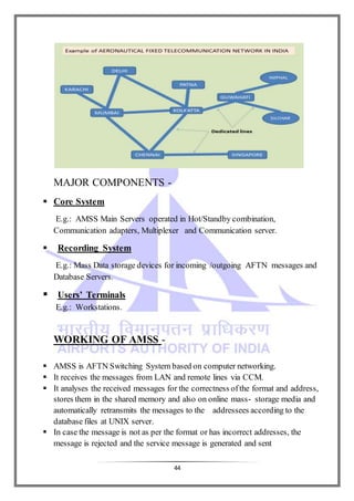
This document provides a summary of communication, navigation and surveillance (CNS) systems used at Lokpriya Gopinath Bordoloi International Airport in Guwahati, India. It includes acknowledgments and contents sections. The main topics covered are Airports Authority of India (AAI), CNS systems including very high frequency (VHF) modulation and antennas, navigation aids, security equipment, air traffic management including radar, and automation including automatic message switching systems.


![12
C (t) = C sin (ωc + φ)
Where:
carrier frequency in Hertz is equal to ωc / 2 π.
C is the carrier amplitude.
φ is the phase of the signal at the start of the reference
time.
Modulating signal equations
m (t) = M sin (ωm + φ)
Where:
modulating signal frequency in Hertz is equal to ωm / 2 π.
M is the carrier amplitude.
φ is the phase of the signal at the start of the reference
time.
Overall modulated signal for a single tone,
y (t) = [ A + M cos (ωm t + φ ] . sin(ωc t)
Or, y (t) = A. sin (ωc t) + M/2 [ sin ((ωc + ωm) t + φ) + M/2 [sin
((ωc - ωm) t - φ)
Where,
Carrier: A . sin (ωc t)
Upper sideband: M/2 [sin ((ωc + ωm) t + φ)]
Lower sideband: M/2 [ sin ((ωc - ωm) t - φ)]
Itcan be seen that for a case where there is 100% modulation, i.e. M = 1, and where
the carrier is not suppressed, i.e. A = 1, then the sidebands havehalf the value of the
carrier, i.e. a quarter of the power each.
Sidebands on an amplitude modulated carrier
when modulated with a single tone](https://image.slidesharecdn.com/airport-report-171211132306/85/Communication-navigation-Surveillance-Report-12-320.jpg)
![13
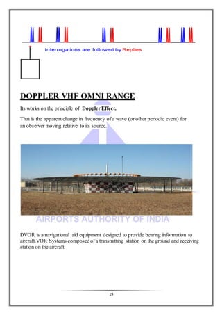
2. FREQUENCYMODULATION:
Frequency modulation (FM) is the encoding of information in a carrier
wave by varying the instantaneous frequency of the wave. (Compare
with amplitude modulation, in which the amplitude of the carrier wave
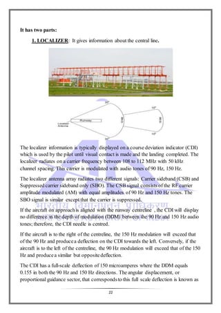
varies, while the frequency remains constant.)
X(t)= A cosθ =A cos (ωt +Ø), θ=cos(ωt+Ø), θ=ωt+Ø
where, A→ Amplitude
θ=ωt +Ø → Angle
Ø → Initial phase
ω →Angular frequency
A is replace by → A + kA cosωmt
→ Amplitude Modulation A(1+ kA cosωmt)cosωct
Ø is replace by→ Ø + kA cosωmt
→ Phase Modulation A cos(ωt+Ø + kA cosωmt)
If by similarity
ω is replaced by (ω + kA cosωmt)
It gives , A cos [(ω+kA cos ωmt )t +Ø]
The angular velocity becomes
d/dt[(ω+kA cos ωmt )t +Ø]
= ω +kA cos ωmt – t kA ωmsin ωmt
1 2 3
Term 3 is ridiculous and impossible to achieve.](https://image.slidesharecdn.com/airport-report-171211132306/85/Communication-navigation-Surveillance-Report-13-320.jpg)
![14
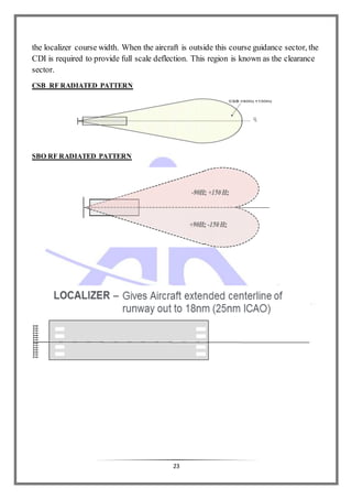
Therefore Instantaneous angular frequency is the rate of change of angle
and NOT repeats NOT the coefficient of t.
• Therefore the frequency modulation is to be conceived by replacing dθ/dt by ωc
+ K Am cos ωmt
• Spectral analysis gives the FM wave as,
Ac Jo(β) cos ω ct + ΣAC Jn (β)[cos(ωc+nωm) t-cos(ωc-ωm)t]
+ ΣAC Jn (β)[cos(ωc+nωm) t-cos(ωc-ωm)t]
• Note that the odd sideband pairs are in RF quadrature and the even pairs are in
RF phase with the carrier.
Therefore by truncating the second sideband onwards the desired AM will not
be available directly.
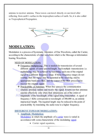
ANTENNA:
An antenna (or aerial) is an electrical device which converts electric power into radio
waves, and vice versa. It is usually used with a radio transmitter or radio receiver.
Antennas are essential components of all equipment that uses radio. They are used in
systems such as radio broadcasting, broadcasttelevision, two-way
radio, communications receivers, radar, cell phones, and satellite communications.
Connect receiver and transmitter in free space. Use to transmit electromagnetic waves
in free space.](https://image.slidesharecdn.com/airport-report-171211132306/85/Communication-navigation-Surveillance-Report-14-320.jpg)


![A presentation on internship from jaipur Airport [AAI]](https://cdn.slidesharecdn.com/ss_thumbnails/airportpptbyadityasept-160404162154-thumbnail.jpg?width=640&height=640&fit=bounds)


![Seminar Report on Airport Authority of India [AAI]](https://cdn.slidesharecdn.com/ss_thumbnails/fullreport-160404161443-thumbnail.jpg?width=640&height=640&fit=bounds)