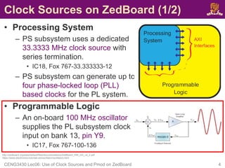
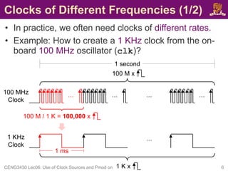
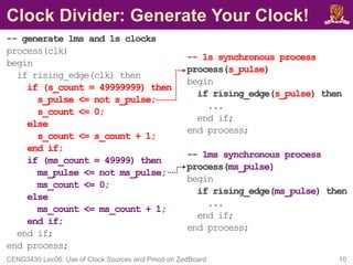
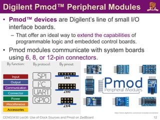
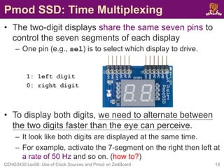
This document discusses clock sources and peripheral modules on the ZedBoard. It describes the different clock sources available, including a 100 MHz on-board oscillator. It also shows how to generate clocks of different frequencies using clock division. As an example, it demonstrates connecting and driving a seven segment display Pmod peripheral module to display digits using time multiplexing at a rate of 50 Hz or faster.


![Clock Sources on ZedBoard (2/2)
• To use the on-board 100 MHz clock input on bank 13,
pin Y9, you need to include the following in your XDC
constraint file:
set_property IOSTANDARD LVCMOS33 [get_ports clk]
set_property PACKAGE_PIN Y9 [get_ports clk]
create_clock -period 10 [get_ports clk]
Note:
• The constraint -period 10 is only used to inform the tool that clock
period is 10 ns (i.e., 100 MHz).
• The constraint -period 10 is NOT used specify or generate a
different clock period from a given clock source.
CENG3430 Lec06: Use of Clock Sources and Pmod on ZedBoard 5
http://zedboard.org/content/changing-frequency-clock-using-createclock](https://image.slidesharecdn.com/lec06useofclocksourcesandperipheralmodulesonzedboard-230202174715-29c91b34/85/Clock-Sources-on-ZedBoard-pdf-5-320.jpg)


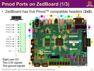
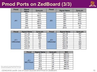
![Pmod Ports on ZedBoard (2/3)
• Four Pmod connectors (JA1, JB1, JC1
and JD1) interface to the PL-side of
the Zynq-7000 AP SoC.
– JA1~JD1 connect to Bank 13 (3.3V).
– JA1~JD1 are placed in adjacent pairs on
the board edge.
• The clearance between JA1 and JB1 and
between JC1 and JD1 are both 10mm.
– JC1 and JD1 are aligned in a dual
configuration and routed differentially.
• To support LVDS running at 525Mbs.
• Pmod (JE1) connects to the PS-side
on MIO pins [0,9-15] in MIO Bank
0/500 (3.3V).
CENG3430 Lec06: Use of Clock Sources and Pmod on ZedBoard 14
JA1
JB1
JC1
JD1
JE1
10mm
10mm](https://image.slidesharecdn.com/lec06useofclocksourcesandperipheralmodulesonzedboard-230202174715-29c91b34/85/Clock-Sources-on-ZedBoard-pdf-13-320.jpg)


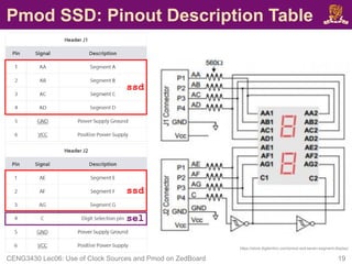
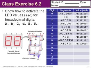
![Pmod SSD: XDC Constraint File
• To drive the Pmod SSD, you also need the following:
set_property IOSTANDARD LVCMOS33 [get_ports ssd]
set_property PACKAGE_PIN Y11 [get_ports {ssd[6]}]
set_property PACKAGE_PIN AA11 [get_ports {ssd[5]}]
set_property PACKAGE_PIN Y10 [get_ports {ssd[4]}]
set_property PACKAGE_PIN AA9 [get_ports {ssd[3]}]
set_property PACKAGE_PIN W12 [get_ports {ssd[2]}]
set_property PACKAGE_PIN W11 [get_ports {ssd[1]}]
set_property PACKAGE_PIN V10 [get_ports {ssd[0]}]
set_property IOSTANDARD LVCMOS33 [get_ports sel]
set_property PACKAGE_PIN W8 [get_ports sel]
CENG3430 Lec06: Use of Clock Sources and Pmod on ZedBoard 21
Digit
Selection
(sel)
Seven
Segments
(ssd)](https://image.slidesharecdn.com/lec06useofclocksourcesandperipheralmodulesonzedboard-230202174715-29c91b34/85/Clock-Sources-on-ZedBoard-pdf-20-320.jpg)