Download free for 30 days
Sign in
Upload
Language (EN)
Support
Business
Mobile
Social Media
Marketing
Technology
Art & Photos
Career
Design
Education
Presentations & Public Speaking
Government & Nonprofit
Healthcare
Internet
Law
Leadership & Management
Automotive
Engineering
Software
Recruiting & HR
Retail
Sales
Services
Science
Small Business & Entrepreneurship
Food
Environment
Economy & Finance
Data & Analytics
Investor Relations
Sports
Spiritual
News & Politics
Travel
Self Improvement
Real Estate
Entertainment & Humor
Health & Medicine
Devices & Hardware
Lifestyle
Change Language
Language
English
Español
Português
Français
Deutsche
Cancel
Save
Submit search
EN
Uploaded by
minamelad457
PDF, PPTX
16 views
Lecture Presentation 7 timer , gpio , 7 segment
Lecture Presentation 7 timer , gpio , 7 segment
Engineering
◦
Read more
0
Save
Share
Embed
Embed presentation
Download
Download as PDF, PPTX
1
/ 26
2
/ 26
3
/ 26
4
/ 26
5
/ 26
6
/ 26
7
/ 26
8
/ 26
9
/ 26
10
/ 26
11
/ 26
12
/ 26
13
/ 26
14
/ 26
15
/ 26
16
/ 26
17
/ 26
18
/ 26
19
/ 26
20
/ 26
21
/ 26
22
/ 26
23
/ 26
24
/ 26
25
/ 26
26
/ 26
More Related Content
PDF
Lecture Presentation 10.pdfLecture Presentation 10.pdf
by
minamelad457
PPT
AVR Fundamentals
by
Vinit Vyas
DOCX
project report on embedded system
by
ram avtar
PDF
Digital Alarm Clock 446 project report
by
Akash Mhankale
DOC
Industrial training report of embedded system and robotics
by
Pallavi Bharti
DOCX
Training Report on embedded Systems and Robotics
by
NIT Raipur
PPTX
timer counter (1).pptx
by
SujalKumar73
PPTX
Embedded systems and robotics by scmandota
by
scmandota
Lecture Presentation 10.pdfLecture Presentation 10.pdf
by
minamelad457
AVR Fundamentals
by
Vinit Vyas
project report on embedded system
by
ram avtar
Digital Alarm Clock 446 project report
by
Akash Mhankale
Industrial training report of embedded system and robotics
by
Pallavi Bharti
Training Report on embedded Systems and Robotics
by
NIT Raipur
timer counter (1).pptx
by
SujalKumar73
Embedded systems and robotics by scmandota
by
scmandota
Similar to Lecture Presentation 7 timer , gpio , 7 segment
PDF
EE6008 MBSD
by
rmkceteee
PPTX
EMBEDDED SYSTEMS & IoT Unit - 2 presentation.pptx
by
girishgandhis
PDF
Micro-controllers (PIC) based Application Development
by
Emertxe Information Technologies Pvt Ltd
PPTX
EC8791 ARM Processor and Peripherals.pptx
by
deviifet2015
PDF
EE6008 MCBSD - Introduction to PIC Micro controller
by
pavihari
PPTX
UNIT 4 & 5 - I nterfacing_Lecture7.pptx
by
naveen088888
PPTX
PIC Presentation_final updated.pptx
by
Shabanam Shikalgar
PPTX
basics to advance arduino timer1 with audio.pptx
by
sumsenchi5
PPTX
embedded system
by
Vivek Ranjan
PDF
Lathe Spindle Sensor
by
JoeCritt
PPT
Programming 8051 Timers
by
ViVek Patel
PPTX
Lec12
by
siddu kadiwal
PPTX
5th unit embedded system and iot design timer and controller
by
gokikayal1998
PPT
UNIT-5.ppt
by
Kannan Thangarajan
DOCX
digital clock atmega16
by
Arcanjo Salazaku
PPT
03- introduction in Interrupts AndTimers.ppt
by
ssuser3cbb4c
DOCX
Arduino 101
by
josnihmurni2907
PPTX
MICROCONTROLLER.pptx
by
fiqrie mohd
PPT
Chp7 pic 16 f84 interfacing - copy
by
mkazree
PPTX
Lec11
by
siddu kadiwal
EE6008 MBSD
by
rmkceteee
EMBEDDED SYSTEMS & IoT Unit - 2 presentation.pptx
by
girishgandhis
Micro-controllers (PIC) based Application Development
by
Emertxe Information Technologies Pvt Ltd
EC8791 ARM Processor and Peripherals.pptx
by
deviifet2015
EE6008 MCBSD - Introduction to PIC Micro controller
by
pavihari
UNIT 4 & 5 - I nterfacing_Lecture7.pptx
by
naveen088888
PIC Presentation_final updated.pptx
by
Shabanam Shikalgar
basics to advance arduino timer1 with audio.pptx
by
sumsenchi5
embedded system
by
Vivek Ranjan
Lathe Spindle Sensor
by
JoeCritt
Programming 8051 Timers
by
ViVek Patel
Lec12
by
siddu kadiwal
5th unit embedded system and iot design timer and controller
by
gokikayal1998
UNIT-5.ppt
by
Kannan Thangarajan
digital clock atmega16
by
Arcanjo Salazaku
03- introduction in Interrupts AndTimers.ppt
by
ssuser3cbb4c
Arduino 101
by
josnihmurni2907
MICROCONTROLLER.pptx
by
fiqrie mohd
Chp7 pic 16 f84 interfacing - copy
by
mkazree
Lec11
by
siddu kadiwal
Recently uploaded
PPTX
Epec Engineered Technologies - Corporate Overview – 2026
by
Epec Engineered Technologies
PDF
I am sharing 'AI in power station ' with you - Hari A K.pdf
by
pugalaiml123
PPTX
UNIT-1.pptx...................................
by
RavinderKaur647214
PPTX
psoc UNIT-3-PPT.pptx unit 3 psoc notes for anna univ regulatuin
by
pandyselvieee
PPTX
Lecture note on the engineering economics
by
Muhammed936900
PDF
BO049FHDMO 0.49 Inch Micro OLED Datasheet
by
Syluxdisplay
PDF
Unconventional reservoirs in petroleum engineering
by
MuhammadHaris61480
PPTX
PQ CHP-1 brief introduction to power quality
by
SureshEtukuriE1
PDF
Layer 1 Blockchain Ecosystem — Executive Brief (Jan 2026)
by
Garima Singh
PPT
Network model of data communication subject
by
hackyourdailylife
PPTX
PQ CHP-2 is about passive pq problems and
by
SureshEtukuriE1
PPTX
PEMET413 -COMPOSITE MATERIALS -KTU MOD 1 LECTURE 4.pptx
by
VINAY B
PDF
22nd Safety Convention by IE(I) dt 27.12.25 by Rajesh Prasad.pdf
by
Rajesh Prasad
PPTX
pH-Responsive Polymers: Synthesis, Properties, and Biomedical Applications
by
BURAKALPERENKARABULU
PDF
Introduction to Human Computer Interaction .pdf
by
akankshanagdeve3
PPTX
MOD 1 (concrete technology -cement,aggregates .pptx
by
tkmmullonkal
PPT
DECISION MAKING SYSTEMS Modelling and Support
by
Anu S S
PPTX
SIMPLE HERMONIC OSCILLATORS pptx
by
Ankit Bera
PPT
ER-model including eer models too.............
by
AndrewNg647846
PPTX
Semiconductor diodes ppt and also characteristics
by
nivishnasece
Epec Engineered Technologies - Corporate Overview – 2026
by
Epec Engineered Technologies
I am sharing 'AI in power station ' with you - Hari A K.pdf
by
pugalaiml123
UNIT-1.pptx...................................
by
RavinderKaur647214
psoc UNIT-3-PPT.pptx unit 3 psoc notes for anna univ regulatuin
by
pandyselvieee
Lecture note on the engineering economics
by
Muhammed936900
BO049FHDMO 0.49 Inch Micro OLED Datasheet
by
Syluxdisplay
Unconventional reservoirs in petroleum engineering
by
MuhammadHaris61480
PQ CHP-1 brief introduction to power quality
by
SureshEtukuriE1
Layer 1 Blockchain Ecosystem — Executive Brief (Jan 2026)
by
Garima Singh
Network model of data communication subject
by
hackyourdailylife
PQ CHP-2 is about passive pq problems and
by
SureshEtukuriE1
PEMET413 -COMPOSITE MATERIALS -KTU MOD 1 LECTURE 4.pptx
by
VINAY B
22nd Safety Convention by IE(I) dt 27.12.25 by Rajesh Prasad.pdf
by
Rajesh Prasad
pH-Responsive Polymers: Synthesis, Properties, and Biomedical Applications
by
BURAKALPERENKARABULU
Introduction to Human Computer Interaction .pdf
by
akankshanagdeve3
MOD 1 (concrete technology -cement,aggregates .pptx
by
tkmmullonkal
DECISION MAKING SYSTEMS Modelling and Support
by
Anu S S
SIMPLE HERMONIC OSCILLATORS pptx
by
Ankit Bera
ER-model including eer models too.............
by
AndrewNg647846
Semiconductor diodes ppt and also characteristics
by
nivishnasece
Lecture Presentation 7 timer , gpio , 7 segment
1.
© 2017 Arm
Limited Timer, GPIO and 7-Segment Peripherals
2.
© 2017 Arm
Limited 2 Module Syllabus General Architecture and Operation Modes of a Timer Peripheral Design and Implementation of • AHB Timer Peripheral • AHB GPIO Peripheral • AHB 7-Segment Display Peripheral
3.
© 2017 Arm
Limited 3 Building a System on a Chip (SoC) Memory VGA Peripheral UART Peripheral Timer Peripheral GPIO Peripheral 7-Segment Peripheral Arm CMSIS-Core Application Programming Interface (API) Application Design (e.g., Game) Arm Cortex-M0 Processor Hardware design Software low-level drivers & libraries programming Software high-level application development Peripheral Drivers AHB
4.
© 2017 Arm
Limited 4 Timer Overview A hardware timer is basically a digital counter that: • Counts regular events, which normally refers to a clock source that has a relatively high and fixed frequency • Increments or decrements at a fixed frequency • Resets itself on reaching zero or a predefined value • Generates an interrupt when reset In contrast, a software timer is a similar function block but implemented in software. Software timers usually: • Are based on hardware timers • Increase or decrease when interrupted by a hardware timer • Offer a lower level of time precision compared with hardware timers • Can have multiple instances that are more than the actual hardware timers
5.
© 2017 Arm
Limited 5 Standard Architecture of Hardware Timers A prescaler • Takes the clock source as its input • Divides the input frequency by a predefined value, e.g., 4, 8, 16 • Outputs the divided frequency to the other components Timer Register Compare Register Prescaler Comparator Interrupt Event Clock Source Capture Register Interrupt Event
6.
© 2017 Arm
Limited 6 Standard Architecture of Hardware Timers A timer register • Increases or decreases at a fixed frequency • Driven by the output from the prescaler; often referred to as ticks Timer Register Compare Register Prescaler Comparator Interrupt Event Clock Source Capture Register Interrupt Event
7.
© 2017 Arm
Limited 7 Standard Architecture of Hardware Timers Compare register • Is preloaded with a desired value, which is periodically compared with the value in the timer register • If the two values are the same, an interrupt can be generated. Timer Register Compare Register Prescaler Comparator Interrupt Event Clock Source Capture Register Interrupt Event
8.
© 2017 Arm
Limited 8 Standard Architecture of Hardware Timers Capture register • Loads the current value from the timer register upon the occurrence of certain events • Can also generate an interrupt upon the occurrence of certain events Timer Register Compare Register Prescaler Comparator Interrupt Event Clock Source Capture Register Interrupt Event
9.
© 2017 Arm
Limited 9 Timer Operation Modes Compare mode Preload the compare register with a desired value Increment or decrement the timer register Compare the values of the timer registers Once the timer and compare register have equal values, generate an interrupt signal Reset the timer register Timer Register Compare Register Prescaler Comparator Interrupt Event Clock Source
10.
© 2017 Arm
Limited 10 Timer Operation Modes Capture mode The event source generates a sequence of pulses Once an event occurs, the capture register will be enabled The capture register then takes a “Snapshot” of the timer An interrupt is sometimes generated Timer Register Capture Register Prescaler Interrupt Event Event Source Capture Enable
11.
© 2017 Arm
Limited 11 Timer Operation Mode Pulse-width modulation (PWM) mode • PWD uses the width of the pulse to modulate an amplitude. • Mainly used for power supplied electrical devices • Pulse frequency ranges from a few kHz (e.g., motor drive) to hundreds of kHz (e.g., audio amplifier, computer power supplies). Voltage Time Logic 1 Logic 0 Power Amplitude
12.
© 2017 Arm
Limited 12 Timer Operation Modes Example of PWM mode: To generate a PWM with 50% duty cycle Preload the compare register with a 50 Increment of the timer register Compare the values of the timer registers Once the values of the timer register exceed that of the compare register, the comparator output will be set to high Reset the timer register when it reaches 100 The comparator output will be reset to a logic zero Timer Register Compare Register Prescaler Comparator Interrupt Event Clock Source Load with duty cycle Value, e.g., 50 Load reset value e.g., 100
13.
© 2017 Arm
Limited 13 Hardware Module Overview Arm Cortex-M0 Processor BRAM System on Chip Arm AMBA 3 AHB-Lite System Bus 32-bit Address Bus 32-bit Data Bus Control Signals VGA Peripheral Monitor UART Peripheral To Host Timer Peripheral GPIO Peripheral LED 7-Segment Peripheral 7-Segment Display
14.
© 2017 Arm
Limited 14 AHB Timer Operation principles: • Contains a 32-bits counter that automatically counts downwards once it is enabled • On reaching zero, it is reset to the value in the “load value” register. • At the same time, an interrupt is generated. AHB Interface Data [31:0] Addr [31:0] Control [31:0] addr Address Decoder Data [31:0] Load [31:0] Current [31:0] Control [31:0] 32-bit Counter Prescaler Clk
15.
© 2017 Arm
Limited 15 Timer Registers The timer peripheral should have at least four registers • Load value register • The reset value when the timer reaches zero • Current value register • The current value of the 32-bit counter • Control register • Used to start/stop a counter and set the prescaler Register Address Size Base address 0x5200_0000 Load value 0x5200_0000 4 Byte Current value 0x5200_0004 4 Byte Control 0x5200_0008 4 Byte
16.
© 2017 Arm
Limited 16 Hardware Module Overview Arm Cortex-M0 Processor BRAM System on Chip Arm AMBA 3 AHB-Lite System Bus 32-bit Address Bus 32-bit Data Bus Control Signals VGA Peripheral Monitor UART Peripheral To Host Timer Peripheral GPIO Peripheral LED 7-Segment Peripheral 7-Segment Display
17.
© 2017 Arm
Limited 17 GPIO Overview General-purpose input/output (GPIO) • Used for general purpose; no special usage defined • Widely used in most applications • The direction of input/output is controlled by the direction register. • A mask register is often used to mask out certain bits. Direction Register Bit [0] out Bit [1] out Bit [2] out Bit [0] in Bit [1] in Bit [2] in To External Devices
18.
© 2017 Arm
Limited 18 AHB GPIO Basic hardware architecture • Only has the basic registers, namely data in, data out, and direction register • Does not have a mask register or any other functions AHB Interface Data [31:0] Addr [31:0] Control [31:0] addr Address Decoder Data [31:0] Output Data [7:0] Input Data [7:0] Direction [7:0] External Devices
19.
© 2017 Arm
Limited 19 GPIO Registers The GPIO peripheral registers include • Data registers • Input data: the data read from external devices • Output data: the data sent to external devices • Direction register • Controls whether it is a read or write operation Register Address Size GPIO base address 0x5300_0000 Data 0x5300_0000 4 Byte Direction 0x5300_0004 4 Byte
20.
© 2017 Arm
Limited 20 Hardware Module Overview Arm Cortex-M0 Processor BRAM System on Chip Arm AMBA 3 AHB-Lite System Bus 32-bit Address Bus 32-bit Data Bus Control Signals VGA Peripheral Monitor UART Peripheral To Host Timer Peripheral GPIO Peripheral LED 7-Segment Peripheral 7-Segment Display
21.
© 2017 Arm
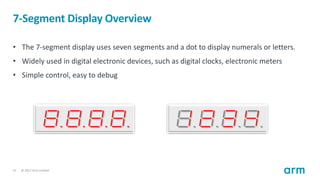
Limited 21 7-Segment Display Overview • The 7-segment display uses seven segments and a dot to display numerals or letters. • Widely used in digital electronic devices, such as digital clocks, electronic meters • Simple control, easy to debug
22.
© 2017 Arm
Limited 22 AHB 7-Segment Display The implementation of the 7-segment display varies from device to device; for example, Digilent Nexys series board uses twelve pins to control the 7-segment display • Segment [6:0]: used to switch on or off one segment • Dot [0:0]: used to switch the dot bit for one digit • Anode [3:0]: used to select the four digits, switch on by “0”
23.
© 2017 Arm
Limited 23 AHB 7-Segment Display To display different values on four digits, they need to be enabled one by one. For example, to display “1234,” the sequence can be: • Anode [3:0]=0111; segment [6:0] = “1” • Anode [3:0]=1011; segment [6:0] = “2”; and so on The looping frequency can be set to about 1000Hz, which is • Slow enough to allow each anode to switch on • Fast enough for the human eye to visualize that all of the digits are on at the same time Number ‘1’ Number ‘2’ Letter ‘A’
24.
© 2017 Arm
Limited 24 AHB 7-Segment Display The values of the four digits are stored in four registers. The clock frequency is divided to loop the four digits. • Here, we insert our first bullet. • Try to keep bullets short and to a minimum. – Next bullet level is slightly smaller for hierarchy Data [31:0] Addr [31:0] Control [31:0] addr Address Decoder Data [31:0] Digit 1 [3:0] Digit 2 [3:0] Digit 3 [3:0] Digit 4 [3:0] Frequency Divider Clk AHB Interface Select [1:0] Anode [3:0] Anode Dec 7-Seg Dec Segments [7:0]
25.
© 2017 Arm
Limited 25 7-Segment Display Registers The 7-segment peripheral has four registers • Digit 1: the first digit on the 7-segment display • Digit 2: the second digit on the 7-segment display • Digit 3: the third digit on the 7-segment display • Digit 4: the forth digit on the 7-segment display Register Address Size Base address 0x5400_0000 Digit 1 0x5400_0000 4 Byte Digit 2 0x5400_0004 4 Byte Digit 3 0x5400_0008 4 Byte Digit 4 0x5400_000C 4 Byte
26.
© 2017 Arm
Limited 26 Memory Space The memory space for all peripherals is allocated as follow: Peripheral Base address End address Size MEM 0x0000_0000 0x4FFF_FFFF 167MB VGA 0x5000_0000 0x50FF_FFFF 16MB UART 0x5100_0000 0x51FF_FFFF 16MB Timer 0x5200_0000 0x52FF_FFFF 16MB GPIO 0x5300_0000 0x53FF_FFFF 16MB 7-segment 0x5400_0000 0x54FF_FFFF 16MB Arm Cortex-M0 Processor BRAM System on Chip Arm AMBA 3 AHB-Lite System Bus 32-bit Address Bus 32-bit Data Bus Control Signals VGA Peripheral Monitor UART Peripheral To Host Timer Peripheral GPIO Peripheral LED 7-Segment Peripheral 7-Segment Display
Download


![© 2017 Arm Limited
14
AHB Timer
Operation principles:
• Contains a 32-bits counter that automatically counts downwards once it is enabled
• On reaching zero, it is reset to the value in the “load value” register.
• At the same time, an interrupt is generated.
AHB
Interface
Data [31:0]
Addr [31:0]
Control [31:0]
addr
Address
Decoder
Data [31:0]
Load [31:0]
Current [31:0]
Control [31:0]
32-bit
Counter
Prescaler
Clk](https://image.slidesharecdn.com/lecturepresentation7-250308151443-3d9735cc/85/Lecture-Presentation-7-timer-gpio-7-segment-14-320.jpg)


![© 2017 Arm Limited
17
GPIO Overview
General-purpose input/output (GPIO)
• Used for general purpose; no special usage defined
• Widely used in most applications
• The direction of input/output is controlled by the direction register.
• A mask register is often used to mask out certain bits.
Direction Register
Bit [0] out
Bit [1] out
Bit [2] out
Bit [0] in
Bit [1] in
Bit [2] in
To External Devices](https://image.slidesharecdn.com/lecturepresentation7-250308151443-3d9735cc/85/Lecture-Presentation-7-timer-gpio-7-segment-17-320.jpg)
![© 2017 Arm Limited
18
AHB GPIO
Basic hardware architecture
• Only has the basic registers, namely data in, data out, and direction register
• Does not have a mask register or any other functions
AHB
Interface
Data [31:0]
Addr [31:0]
Control [31:0]
addr
Address
Decoder
Data [31:0]
Output Data [7:0]
Input Data [7:0]
Direction [7:0]
External
Devices](https://image.slidesharecdn.com/lecturepresentation7-250308151443-3d9735cc/85/Lecture-Presentation-7-timer-gpio-7-segment-18-320.jpg)


![© 2017 Arm Limited
22
AHB 7-Segment Display
The implementation of the 7-segment display varies from device to device; for example,
Digilent Nexys series board uses twelve pins to control the 7-segment display
• Segment [6:0]: used to switch on or off one segment
• Dot [0:0]: used to switch the dot bit for one digit
• Anode [3:0]: used to select the four digits, switch on by “0”](https://image.slidesharecdn.com/lecturepresentation7-250308151443-3d9735cc/85/Lecture-Presentation-7-timer-gpio-7-segment-22-320.jpg)
![© 2017 Arm Limited
23
AHB 7-Segment Display
To display different values on four digits, they need to be enabled one by one. For example, to display
“1234,” the sequence can be:
• Anode [3:0]=0111; segment [6:0] = “1”
• Anode [3:0]=1011; segment [6:0] = “2”; and so on
The looping frequency can be set to about 1000Hz, which is
• Slow enough to allow each anode to switch on
• Fast enough for the human eye to visualize that all of the digits are on at the same time
Number ‘1’ Number ‘2’ Letter ‘A’](https://image.slidesharecdn.com/lecturepresentation7-250308151443-3d9735cc/85/Lecture-Presentation-7-timer-gpio-7-segment-23-320.jpg)
![© 2017 Arm Limited
24
AHB 7-Segment Display
The values of the four digits are stored in four registers.
The clock frequency is divided to loop the four digits.
• Here, we insert our first bullet.
• Try to keep bullets short and to a minimum.
– Next bullet level is slightly smaller for hierarchy
Data [31:0]
Addr [31:0]
Control [31:0]
addr
Address
Decoder
Data [31:0]
Digit 1 [3:0]
Digit 2 [3:0]
Digit 3 [3:0]
Digit 4 [3:0]
Frequency
Divider
Clk
AHB
Interface
Select [1:0]
Anode [3:0]
Anode
Dec
7-Seg
Dec
Segments [7:0]](https://image.slidesharecdn.com/lecturepresentation7-250308151443-3d9735cc/85/Lecture-Presentation-7-timer-gpio-7-segment-24-320.jpg)