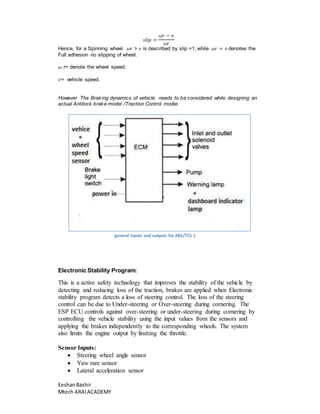
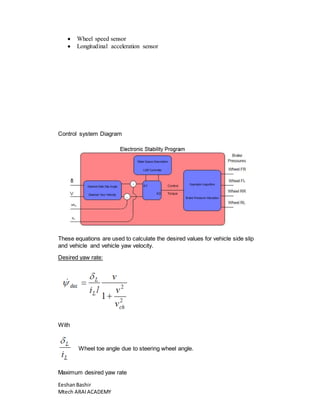
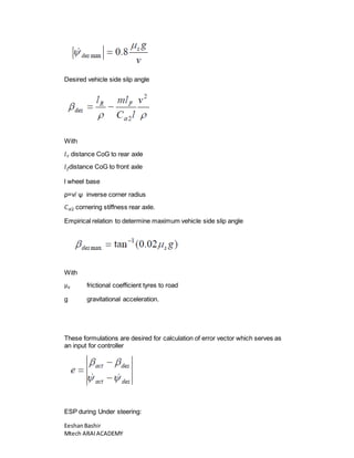
Chassis Control Systems: 
ABS-Antilock Braking system:Anti-lock braking systems (ABS) are active 
safety features designed to help drivers retain steering control by preventing 
wheels from locking up during an episode of heavy braking 
Sensor inputs: 
 Wheel speed sensor 
 Vehicle speed sensor 
 Brake lever position sensor 
Controller unit. 
Calculated slip on the basis of the formula 
Eeshan Bashir 
Mtech ARAI ACADEMY 
푠푙푖푝 = 
푣 − 휔푟 
푣 
Hence, for a locked wheel 휔푟 =0 is described by slip =1, while 휔푟 = 푣 denotes the 
free motion of the wheel. 
휔 r= denote the wheel speed. 
However The Braking dynamics of vehicle needs to be considered while designing an 
actual Antilock brake model 
The parameters that affect ABS system are: 
 Drive torque 
 Wheel Mass 
 Gravity(g) 
 Wheel radius 
 Moment of inertia 
 Braking torque 
Notes: 
 No wheel lock allowed to occur for speeds above 4 m/s 
 wheel lock for a period of less than 0.2 seconds is allowed for speeds in the 
range of 0.8 . . .4 m/s 
 for speeds below 0.8 m/s the wheels are allowed to lock 
 
Traction control system: is typically a secondary function of the anti-lock 
braking system. TCS is activated when throttle input and engine torque are 
mismatched to road surface conditions causing wheel slip, designed to prevent 
loss of traction of driven road wheels. 
Intervention consists of one or more of the following: 
 Brake force applied to one or more wheels 
 Reduction or suppression of spark sequence to one or more cylinders 
 Reduction of fuel supply to one or more cylinders 
 Closing the throttle, if the vehicle is fitted with drive by wire throttle 
 In turbocharger vehicles, a boost control solenoid is actuated to reduce 
boost and therefore engine power. 
Calculation of Slip in traction system. 
Calculated slip on the basis of the formula
Eeshan Bashir 
Mtech ARAI ACADEMY 
푠푙푖푝 = 
휔푟 − 푣 
휔푟 
Hence, for a Spinning wheel 휔푟 > 푣 is described by slip =1, while 휔푟 = 푣 denotes the 
Full adhesion no slipping of wheel. 
휔 r= denote the wheel speed. 
푣= vehicle speed. 
However The Braking dynamics of vehicle needs to be considered while designing an 
actual Antilock brake model /Traction Control model. 
general inputs and outputs for ABS/TCS 1 
Electronic Stability Program: 
This is a active safety technology that improves the stability of the vehicle by 
detecting and reducing loss of the traction, brakes are applied when Electronic 
stability program detects a loss of steering control. The loss of the steering 
control can be due to Under-steering or Over-steering during cornering. The 
ESP ECU controls against over-steering or under-steering during cornering by 
controlling the vehicle stability using the input values from the sensors and 
applying the brakes independently to the corresponding wheels. The system 
also limits the engine output by limiting the throttle. 
Sensor Inputs: 
 Steering wheel angle sensor 
 Yaw rare sensor 
 Lateral acceleration sensor
 Wheel speed sensor 
 Longitudinal acceleration sensor 
Control system Diagram 
These equations are used to calculate the desired values for vehicle side slip 
and vehicle and vehicle yaw velocity. 
Desired yaw rate: 
With 
Wheel toe angle due to steering wheel angle. 
Maximum desired yaw rate 
Eeshan Bashir 
Mtech ARAI ACADEMY
Desired vehicle side slip angle 
With 
푙 푟 distance CoG to rear axle 
푙푓distance CoG to front axle 
l wheel base 
ρ=v/ ψ inverse corner radius 
퐶훼2 cornering stiffness rear axle. 
Empirical relation to determine maximum vehicle side slip angle 
With 
μ푠 frictional coefficient tyres to road 
g gravitational acceleration. 
These formulations are desired for calculation of error vector which serves as 
an input for controller 
ESP during Under steering: 
Eeshan Bashir 
Mtech ARAI ACADEMY
Under steering is when the steering wheel is steered to a certain angle during 
the front tires slip towards the reverse direction of the desired direction. The 
ESP system recognizes the directional angle with the steering wheel angle 
sensor and the slipping route that occurs reversely against the vehicle 
cornering direction during under-steering with the yaw rate sensor and the 
lateral sensor. Then the ESP system applies the brake at the rear inner wheel 
to compensate the yaw moment value. 
ESP during Over steering: 
Oversteering is when the wheel is steered to a certain angle during driving and 
the rear tires slip outward losing traction. ESP system recognizes the 
directional angle with the steering angle sensor and senses the slipping route 
that occurs towards the vehicle cornering direction during over steering with 
the yaw rate sensor and the lateral sensor. Then the ESP brakes at the front 
outer wheel to compensate the yaw moment value. 
Some other Chassis control systems include: 
Advanced Driver Assistance Systems (ADAS) 
Electronic chassis control (suspension, steering, damping etc.) 
Eeshan Bashir 
Mtech ARAI ACADEMY

Chassis control system algorithms and mathematical analysis

  • 1.
    Chassis Control Systems: ABS-Antilock Braking system:Anti-lock braking systems (ABS) are active safety features designed to help drivers retain steering control by preventing wheels from locking up during an episode of heavy braking Sensor inputs:  Wheel speed sensor  Vehicle speed sensor  Brake lever position sensor Controller unit. Calculated slip on the basis of the formula Eeshan Bashir Mtech ARAI ACADEMY 푠푙푖푝 = 푣 − 휔푟 푣 Hence, for a locked wheel 휔푟 =0 is described by slip =1, while 휔푟 = 푣 denotes the free motion of the wheel. 휔 r= denote the wheel speed. However The Braking dynamics of vehicle needs to be considered while designing an actual Antilock brake model The parameters that affect ABS system are:  Drive torque  Wheel Mass  Gravity(g)  Wheel radius  Moment of inertia  Braking torque Notes:  No wheel lock allowed to occur for speeds above 4 m/s  wheel lock for a period of less than 0.2 seconds is allowed for speeds in the range of 0.8 . . .4 m/s  for speeds below 0.8 m/s the wheels are allowed to lock  Traction control system: is typically a secondary function of the anti-lock braking system. TCS is activated when throttle input and engine torque are mismatched to road surface conditions causing wheel slip, designed to prevent loss of traction of driven road wheels. Intervention consists of one or more of the following:  Brake force applied to one or more wheels  Reduction or suppression of spark sequence to one or more cylinders  Reduction of fuel supply to one or more cylinders  Closing the throttle, if the vehicle is fitted with drive by wire throttle  In turbocharger vehicles, a boost control solenoid is actuated to reduce boost and therefore engine power. Calculation of Slip in traction system. Calculated slip on the basis of the formula
  • 2.
    Eeshan Bashir MtechARAI ACADEMY 푠푙푖푝 = 휔푟 − 푣 휔푟 Hence, for a Spinning wheel 휔푟 > 푣 is described by slip =1, while 휔푟 = 푣 denotes the Full adhesion no slipping of wheel. 휔 r= denote the wheel speed. 푣= vehicle speed. However The Braking dynamics of vehicle needs to be considered while designing an actual Antilock brake model /Traction Control model. general inputs and outputs for ABS/TCS 1 Electronic Stability Program: This is a active safety technology that improves the stability of the vehicle by detecting and reducing loss of the traction, brakes are applied when Electronic stability program detects a loss of steering control. The loss of the steering control can be due to Under-steering or Over-steering during cornering. The ESP ECU controls against over-steering or under-steering during cornering by controlling the vehicle stability using the input values from the sensors and applying the brakes independently to the corresponding wheels. The system also limits the engine output by limiting the throttle. Sensor Inputs:  Steering wheel angle sensor  Yaw rare sensor  Lateral acceleration sensor
  • 3.
     Wheel speedsensor  Longitudinal acceleration sensor Control system Diagram These equations are used to calculate the desired values for vehicle side slip and vehicle and vehicle yaw velocity. Desired yaw rate: With Wheel toe angle due to steering wheel angle. Maximum desired yaw rate Eeshan Bashir Mtech ARAI ACADEMY
  • 4.
    Desired vehicle sideslip angle With 푙 푟 distance CoG to rear axle 푙푓distance CoG to front axle l wheel base ρ=v/ ψ inverse corner radius 퐶훼2 cornering stiffness rear axle. Empirical relation to determine maximum vehicle side slip angle With μ푠 frictional coefficient tyres to road g gravitational acceleration. These formulations are desired for calculation of error vector which serves as an input for controller ESP during Under steering: Eeshan Bashir Mtech ARAI ACADEMY
  • 5.
    Under steering iswhen the steering wheel is steered to a certain angle during the front tires slip towards the reverse direction of the desired direction. The ESP system recognizes the directional angle with the steering wheel angle sensor and the slipping route that occurs reversely against the vehicle cornering direction during under-steering with the yaw rate sensor and the lateral sensor. Then the ESP system applies the brake at the rear inner wheel to compensate the yaw moment value. ESP during Over steering: Oversteering is when the wheel is steered to a certain angle during driving and the rear tires slip outward losing traction. ESP system recognizes the directional angle with the steering angle sensor and senses the slipping route that occurs towards the vehicle cornering direction during over steering with the yaw rate sensor and the lateral sensor. Then the ESP brakes at the front outer wheel to compensate the yaw moment value. Some other Chassis control systems include: Advanced Driver Assistance Systems (ADAS) Electronic chassis control (suspension, steering, damping etc.) Eeshan Bashir Mtech ARAI ACADEMY