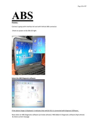
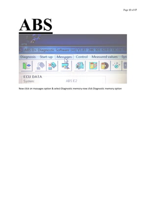
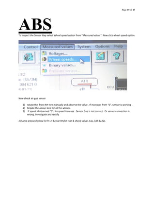
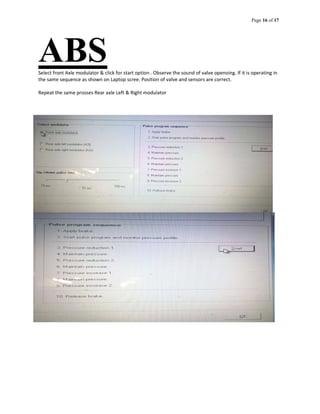
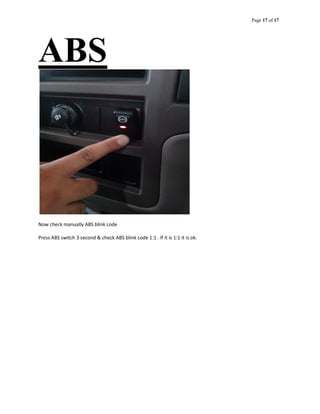
Page 1 of 17
ABSANTILOCK BRAKING SYSTEM
• Objectives of ABS
• Components of ABS
• Working of ABS
• Diagnosis of the ABS
Introduction
3.1.mp4 Motorcycle2.mp4
3.2 Training WO
ABS.mp4
3.3 Training
WABS.mp4
• Ability of brakes to do their job
– Limited by tire grip to road surface
– Skids could be avoided if driver could release brake pressure just before wheel locks
– When wheel stops turning, friction generates heat, causing tire to lose traction
– Slip rate of 50% means the wheel is rolling 50% slower than freely rolling tire
– Maximum traction occurs at ten to twenty percent slip
Page 2 of 17
ABS
`
Page 3 of 17
ABS
ABS2.mp4 ABS3.mp4 Volvo.mp4
Page 4 of 17
ABSOBJECTIVES OF ABS
 To reduce stopping distance
o The road surface type and conditions can be inferred from the vehicle's braking pressure,
wheel slip measurements, and deceleration rate comparisons.
o The wheel slip is regulated so that the road adhesion coefficient is maximized. By keeping all
of the wheels of a vehicle near the maximum friction coefficient, an antilock system can
attain maximum fictional force
o In turn, this strategy leads to the minimization of the vehicle stopping distance.
 Stability
o A locked-up wheel generates a reduced braking force, smaller than the peak value of the
available adhesion between tires and road. A locked-up wheel will also lose its capability to
sustain any lateral force. This may result in the loss of vehicle stability.
o The basic purpose of a conventional ABS system is thus to prevent any wheel from locking and
to keep the longitudinal slip in an operational range by cycling the braking pressure.
 Steer-ability
o Good peak frictional force control is necessary in order to achieve satisfactory lateral forces
and, therefore, satisfactory steer-ability.
o If an obstacle appears without warning, emergency braking may not be sufficient. When the
wheels are locked, car no longer respond to the driver’s steering intention.
o With ABS car remains steerable even during emergency braking, and thus the obstacle can be
safely avoided.
Training W &
WABS.mp4
Page 5 of 17
ABSComponents of ABS
The primary components of the ABS braking system are:
 Electronic control unit (ECU)
o It receives signals from the sensors in the circuit and controls the brake pressure at the road
wheels according to the data analysed by the Unit.
o ECU assists the vehicle operator to prevent wheel lockup by regulating the wheel slip.
The ECU is installed in the protected environment of the driver’s cab. For trailers, the ECU is located in a
special protective housing which is mounted on the vehicle frame.
Always switch off the ignition before removing or installing the electronic control unit, i.e. always switch off
the ignition when disconnecting or connecting the ECU plug.
 Hydraulic control unit or modulator
o It receives operating signals from the ECU to apply or release the brakes under ABS conditions.
o It executes the commands using three solenoid valves connected in series with the master
cylinder and the brake circuits- one valve for each front wheel hydraulic circuit, and one for
both of the rear wheels. Thus brakes can be actuated by controlling hydraulic pressure.
 Power booster and master cylinder assembly
o It is activated when the driver pushes down on the brake pedal. The master cylinder
transforms the applied pedal force into hydraulic pressure which is transmitted
simultaneously to all four wheels.
o It provides the power assistance required during braking.
Page 6 of 17
ABS
ABS Solenoid Valves
Page 7 of 17
ABS Wheel sensor unit
o Speed sensors are comprised of a magnet wrapped in a coil and a toothed sensor ring. An
electrical field given off by the contact between the magnet and the toothed ring creates an
AC voltage.
o The voltage frequency is directly proportional to the wheel's rotational speed.
o It monitors the rotational speed of the wheel and transmits this data to the ABS control
module.
Sensor
Sensor Installation View
Page 8 of 17
ABS
Sensor diagram and Working
Wheel Speed sensor frequency changes as Wheel speed increases or decreases
Resistance of the sensor coil, proper setting for the air gap and the sensor/ wheel allocation can be tested
using the ABS Tester or the Diagnostic Controller.
Page 9 of 17
ABS
Working of ABS
 If a wheel-speed sensor signals a lock up - the ECU sends a current to the hydraulic unit. This energizes
the solenoid valve. The action of the valve isolates the brake circuit from the master cylinder. This
stops the braking pressure at that wheel from rising, and keeps it constant. It allows wheel velocity to
increase and slip to decrease.
 When the velocity increases, ECU re-applies the brake pressure to restrict the wheel slip to a
particular value.
 Hydraulic control unit controls the brake pressure in each wheel cylinder based on the inputs from the
system sensor. This in result controls the wheel speed.
Page 10 of 17
ABSTesting the Anti-Lock Braking System (ABS)
ABS warning lamp for motor vehicles
ABS warning lamp for trailers
Warning lamp for motor vehicles
The lamp lights up when the ignition is switched on. It goes out after approx.
2 seconds if the ABS safety circuit has not detected any faults or
The vehicle has exceeded a speed of approx. 7 km/h.
Warning lamp for trailers
This lamp lights up when the ignition is switched on, provided a trailer With ABS has been hitched and the ABS
connector is plugged in. The Lamp also goes out (as for warning lamps for towing vehicles) after Around 2
seconds if the ABS safety circuit has not detected any faults or The vehicle has reached a speed of approx. 7
km/h. Both warning lamps stay off even when the vehicle stops in traffic (e. g. at a red traffic light). When the
ABS warning lamps have gone out, the Anti-Lock Braking System is operational. However, ABS control will not
commence until one or several wheels show a tendency to lock during braking action
Page 11 of 17
ABSDiagnosis of the ABS
Diagnosis of the ABS ECU includes
– Fault analysis (fault readout and storage)
– Setting the system parameters
– Start-up
Laptop (Software) with Interface Kit
3.4 Wabco Diagnosis
kit.mp4
Page 12 of 17
ABSProcess:-
Connect Laptop with interface kit and with Vehicle ABS connector.
Check on power on & USB LED light
Select the ABS Diagnosis software
If the above image is displayed. It indicates that vehicle ECU is connected with diagnosis Software .
Now select air ABS Diagnostic software (air brake vehicle) / HBS Addon-E Diagnostic software (Hyd vehicle)
& check current massage
Page 13 of 17
ABS
Now click on massages option & select Diagnostic memory now click Diagnostic memory option
Page 14 of 17
ABS
Page 15 of 17
ABSTo inspect the Sensor Gap select Wheel speed option from “Measured value “. Now click wheel speed option
Now check air gap sensor
1) rotate the front RH tyre manually and observe the value . If increases from “0”. Sensor is working .
2) Repate the above step for all the wheels.
3) If speed id observed “0”. No speed increase . Sensor Gap is not correct. Or sensor connection is
wrong. Investigate and rectify
2) Same prosses follow for fr LH & rear RH/LH tyer & check values A1L, A2R & A2L
Page 16 of 17
ABSSelect front Axle modulator & click for start option . Observe the sound of valve openoing. If it is operating in
the same sequence as shown on Laptop scree. Position of valve and sensors are correct.
Repeat the same prosses Rear axle Left & Right modulator
Page 17 of 17
ABS
Now check manually ABS blink code
Press ABS switch 3 second & check ABS blink code 1:1 . If it is 1:1 it is ok.

Abs learning

  • 1.
    Page 1 of17 ABSANTILOCK BRAKING SYSTEM • Objectives of ABS • Components of ABS • Working of ABS • Diagnosis of the ABS Introduction 3.1.mp4 Motorcycle2.mp4 3.2 Training WO ABS.mp4 3.3 Training WABS.mp4 • Ability of brakes to do their job – Limited by tire grip to road surface – Skids could be avoided if driver could release brake pressure just before wheel locks – When wheel stops turning, friction generates heat, causing tire to lose traction – Slip rate of 50% means the wheel is rolling 50% slower than freely rolling tire – Maximum traction occurs at ten to twenty percent slip
  • 2.
    Page 2 of17 ABS `
  • 3.
    Page 3 of17 ABS ABS2.mp4 ABS3.mp4 Volvo.mp4
  • 4.
    Page 4 of17 ABSOBJECTIVES OF ABS  To reduce stopping distance o The road surface type and conditions can be inferred from the vehicle's braking pressure, wheel slip measurements, and deceleration rate comparisons. o The wheel slip is regulated so that the road adhesion coefficient is maximized. By keeping all of the wheels of a vehicle near the maximum friction coefficient, an antilock system can attain maximum fictional force o In turn, this strategy leads to the minimization of the vehicle stopping distance.  Stability o A locked-up wheel generates a reduced braking force, smaller than the peak value of the available adhesion between tires and road. A locked-up wheel will also lose its capability to sustain any lateral force. This may result in the loss of vehicle stability. o The basic purpose of a conventional ABS system is thus to prevent any wheel from locking and to keep the longitudinal slip in an operational range by cycling the braking pressure.  Steer-ability o Good peak frictional force control is necessary in order to achieve satisfactory lateral forces and, therefore, satisfactory steer-ability. o If an obstacle appears without warning, emergency braking may not be sufficient. When the wheels are locked, car no longer respond to the driver’s steering intention. o With ABS car remains steerable even during emergency braking, and thus the obstacle can be safely avoided. Training W & WABS.mp4
  • 5.
    Page 5 of17 ABSComponents of ABS The primary components of the ABS braking system are:  Electronic control unit (ECU) o It receives signals from the sensors in the circuit and controls the brake pressure at the road wheels according to the data analysed by the Unit. o ECU assists the vehicle operator to prevent wheel lockup by regulating the wheel slip. The ECU is installed in the protected environment of the driver’s cab. For trailers, the ECU is located in a special protective housing which is mounted on the vehicle frame. Always switch off the ignition before removing or installing the electronic control unit, i.e. always switch off the ignition when disconnecting or connecting the ECU plug.  Hydraulic control unit or modulator o It receives operating signals from the ECU to apply or release the brakes under ABS conditions. o It executes the commands using three solenoid valves connected in series with the master cylinder and the brake circuits- one valve for each front wheel hydraulic circuit, and one for both of the rear wheels. Thus brakes can be actuated by controlling hydraulic pressure.  Power booster and master cylinder assembly o It is activated when the driver pushes down on the brake pedal. The master cylinder transforms the applied pedal force into hydraulic pressure which is transmitted simultaneously to all four wheels. o It provides the power assistance required during braking.
  • 6.
    Page 6 of17 ABS ABS Solenoid Valves
  • 7.
    Page 7 of17 ABS Wheel sensor unit o Speed sensors are comprised of a magnet wrapped in a coil and a toothed sensor ring. An electrical field given off by the contact between the magnet and the toothed ring creates an AC voltage. o The voltage frequency is directly proportional to the wheel's rotational speed. o It monitors the rotational speed of the wheel and transmits this data to the ABS control module. Sensor Sensor Installation View
  • 8.
    Page 8 of17 ABS Sensor diagram and Working Wheel Speed sensor frequency changes as Wheel speed increases or decreases Resistance of the sensor coil, proper setting for the air gap and the sensor/ wheel allocation can be tested using the ABS Tester or the Diagnostic Controller.
  • 9.
    Page 9 of17 ABS Working of ABS  If a wheel-speed sensor signals a lock up - the ECU sends a current to the hydraulic unit. This energizes the solenoid valve. The action of the valve isolates the brake circuit from the master cylinder. This stops the braking pressure at that wheel from rising, and keeps it constant. It allows wheel velocity to increase and slip to decrease.  When the velocity increases, ECU re-applies the brake pressure to restrict the wheel slip to a particular value.  Hydraulic control unit controls the brake pressure in each wheel cylinder based on the inputs from the system sensor. This in result controls the wheel speed.
  • 10.
    Page 10 of17 ABSTesting the Anti-Lock Braking System (ABS) ABS warning lamp for motor vehicles ABS warning lamp for trailers Warning lamp for motor vehicles The lamp lights up when the ignition is switched on. It goes out after approx. 2 seconds if the ABS safety circuit has not detected any faults or The vehicle has exceeded a speed of approx. 7 km/h. Warning lamp for trailers This lamp lights up when the ignition is switched on, provided a trailer With ABS has been hitched and the ABS connector is plugged in. The Lamp also goes out (as for warning lamps for towing vehicles) after Around 2 seconds if the ABS safety circuit has not detected any faults or The vehicle has reached a speed of approx. 7 km/h. Both warning lamps stay off even when the vehicle stops in traffic (e. g. at a red traffic light). When the ABS warning lamps have gone out, the Anti-Lock Braking System is operational. However, ABS control will not commence until one or several wheels show a tendency to lock during braking action
  • 11.
    Page 11 of17 ABSDiagnosis of the ABS Diagnosis of the ABS ECU includes – Fault analysis (fault readout and storage) – Setting the system parameters – Start-up Laptop (Software) with Interface Kit 3.4 Wabco Diagnosis kit.mp4
  • 12.
    Page 12 of17 ABSProcess:- Connect Laptop with interface kit and with Vehicle ABS connector. Check on power on & USB LED light Select the ABS Diagnosis software If the above image is displayed. It indicates that vehicle ECU is connected with diagnosis Software . Now select air ABS Diagnostic software (air brake vehicle) / HBS Addon-E Diagnostic software (Hyd vehicle) & check current massage
  • 13.
    Page 13 of17 ABS Now click on massages option & select Diagnostic memory now click Diagnostic memory option
  • 14.
    Page 14 of17 ABS
  • 15.
    Page 15 of17 ABSTo inspect the Sensor Gap select Wheel speed option from “Measured value “. Now click wheel speed option Now check air gap sensor 1) rotate the front RH tyre manually and observe the value . If increases from “0”. Sensor is working . 2) Repate the above step for all the wheels. 3) If speed id observed “0”. No speed increase . Sensor Gap is not correct. Or sensor connection is wrong. Investigate and rectify 2) Same prosses follow for fr LH & rear RH/LH tyer & check values A1L, A2R & A2L
  • 16.
    Page 16 of17 ABSSelect front Axle modulator & click for start option . Observe the sound of valve openoing. If it is operating in the same sequence as shown on Laptop scree. Position of valve and sensors are correct. Repeat the same prosses Rear axle Left & Right modulator
  • 17.
    Page 17 of17 ABS Now check manually ABS blink code Press ABS switch 3 second & check ABS blink code 1:1 . If it is 1:1 it is ok.