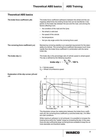
This document provides information about anti-lock braking systems (ABS) and anti-slip regulation (ASR) for commercial vehicles. It discusses the development and benefits of ABS and ASR, how they work, their components, and additional systems like electronic stability control. The document covers the theoretical basics of ABS and ASR, explaining concepts like brake force coefficient, cornering force coefficient, and brake slip. It also includes diagrams illustrating the slip curves under different road conditions.
![10
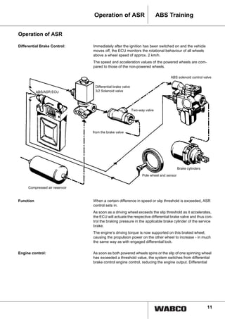
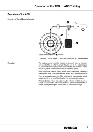
ABS Training Operation of the ABS
Example of an ABS control cycle: The values recorded relate to the control cycle of one wheel. The initial
vehicle speed is 80 km/h.
On the abscissa, the control cycles are recorded relative to time. In the
area of the ordinate, the braking pressure is shown in the bottom section,
and the middle section shows the reference and wheel speeds. The so-
lenoid valve pulses appear in the top section.
The control procedure The driver actuates the braking system. The brake pressure increases.
The speed of the observed wheel suddenly drops much faster than the
reference speed. Although the wheel is still within the stable braking
range (i.e. between 10 % and 30 % slip), the electronic control unit al-
ready starts the control procedure.
The ABS solenoid valve is actuated and rapidly reduces the pressure in
the brake cylinder of that wheel, and the wheel begins to accelerate
again.
The electronics cause the solenoid control valve to reverse, keeping the
braking pressure at a constant level until the wheel runs within the stable
slip range again.
As soon as more braking force can be transferred, the braking pressure
is increased by means of pulsing - i. e. alternately holding and increasing
pressure. If the wheel speed drops significantly relative to the reference
speed during this process, a new control cycle begins.
This procedure is repeated for as long as the brake pedal is pressed too
hard for these road conditions or until the vehicle comes to a halt. The
maximum control frequency which can be achieved here is 3 to 5 cycles
per second.
electrical solenoid valve signals
Reference speed
Wheel speed
Braking pressure
Time in s
Speed[km/h]Brakingpressure(bar)](https://image.slidesharecdn.com/anti-lockbrakingsystem-161217152456/85/Anti-lock-braking-system-10-320.jpg)