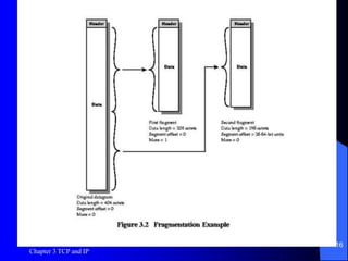
Chapter 3 TCP and IP
1
Chapter 3
TCP and IP
Chapter 3 TCP and IP
2
Introduction
 Transmission Control Protocol (TCP)
 User Datagram Protocol (UDP)
 Internet Protocol (IP)
 IPv6
Chapter 3 TCP and IP
3
TCP
 RFC 793, RFC 1122
 Outgoing data is logically a stream of
octets from user
 Stream broken into blocks of data, or
segments
 TCP accumulates octets from user until
segment is large enough, or data marked
with PUSH flag
 User can mark data as URGENT
Chapter 3 TCP and IP
4
 Similarly, incoming data is a stream of
octets presented to user
 Data marked with PUSH flag triggers
delivery of data to user, otherwise TCP
decides when to deliver data
 Data marked with URGENT flag causes
user to be signaled
Chapter 3 TCP and IP
5
Checksum Field
 Applied to data segment and part of the
header (Pseudo header). The pseudo
header includes the source and destination
IP addresses, protocol and segment length
fields from the IP header. TCP protects
itself from mis-delivery by IP.
 Protects against bit errors in user data and
addressing information
 Filled in at source
 Checked at destination
Chapter 3 TCP and IP
6
Options
 Maximum segment size – defined in RFC 793 –
it specifies the maximum segment size in octets
that will be accepted in this connection. 16-bit
and can only be used in the initial connection
request segments.
 Window scale factor – The value of F in 2F,
where the value of the window field is
multiplied. Max value of F is 14 and this option
is only used in the initial connection request
segments.
 Timestamp
Chapter 3 TCP and IP
7
Figure 2.1
Some of the Fields
 Sequence Number (32 bits) – sequence number of the first data
octet in this segment except when SYN flag is set. If set this
field is ISN + 1 – ISN and the first data octet.
 Data offset (4 bits) – number of 32-bit words in the header.
 Window (16 bit) – Flow control credit allocation, in octets.
Contains the number of data octets beginning with the one
indicated in the ACK field that the sender is willing to accept.
 Flags (6 bits) – URG, ACK, PSH, RST, SYN and FIN.
 Urgent Pointer (16 bits) – points to the last octet in a sequence
of urgent data. This allows the receiver to know how much
urgent data is coming.
Chapter 3 TCP and IP
8
Chapter 3 TCP and IP
9
UDP
 RFC 768
 Connectionless, unreliable
 Less overhead
 Simply adds port addressing to IP
 Checksum is optional
Chapter 3 TCP and IP
10
Appropriate Uses of UDP
 Inward data collection – as in sensor ntks
 Outward data dissemination – broadcast
message to users.
 Request-response – when applications
control the transaction service.
 Real-time applications – in voice and
telemetry.
Chapter 3 TCP and IP
11
IP
 RFC 791
 Field highlights:
– Type of service, defined in RFC 1349, see
Figure 3.1 – provides guidance to end-system
IP modules and to routers along the
datagram’s path.
– More bit
– Don’t fragment bit
– Time to live (similar to a hop count)
Chapter 3 TCP and IP
12
Figure 2.2
Chapter 3 TCP and IP
13
Figure 3.1
Chapter 3 TCP and IP
14
Fragmentation and Reassembly
 Only two of the 3 bits in the flag field are currently defined.
The more bit and the don’t fragment bit.
 Networks may have different maximum packet size
 Router may need to fragment datagrams before sending to next
network
 Fragments may need further fragmenting in later networks
 In IP, Reassembly is done only at final destination since
fragments may take different routes.
– What is the disadvantage of this scheme (pkts can only get smaller as
data moves through the internet).
– What disadvantages result if intermediate routers do the reassembly?
(large buffers are required at routers and all fragments must pass
through the same router)
Fragmentation and Reassembly
 The IP fragmentation technique uses the following information from the IP
header:
– Identification (ID), Data Length (difference between total length and Internet header
length), Fragment offset, More Flag
 The source end system creates a datagram with a Data Length equal to the
entire length of the data field, with Offset = 0, and a More Flag set to 0
(False)
 To fragment a long datagram, an IP module in a router performs the
following tasks:
– Create two new datagrams and copy the header fields of the incoming datagram into both.
– Divide the incoming user data field into two approximately equal portions along a 64-bit
boundary, placing one portion in each new datagram. The first portion must be a multiple
of 64 bits.
– Set the Data Length of the first new datagram to the length of the inserted data, and set
More Flag to 1 (true). The Offset field is unchanged.
– Set the Data Length of the second new datagram to the length of the inserted data, and
add the length of the first data portion divided by 8 to the Offset field. The More Flag
remains the same (in this case false if fragmented to two).
Chapter 3 TCP and IP
15
Chapter 3 TCP and IP
16
Figure 3.2
Chapter 3 TCP and IP
17
Type of Service TOS Subfield
 Set by source system – provides guidance
on selection of the next path for this
segment.
 Routers may ignore TOS
 Router may respond to requested TOS
value through:
– Route selection – IPv4 focuses here
– Subnetwork service
– Queuing discipline
TOS
 When TOS routing is implemented, RFC 1812 specifies the ff rules for
forwarding a datagram with a nonzero TOS.
– The router determines all available routes to the destination; if there
are none, the datagram is discarded.
– If one or more routes have the same TOS as the requested TOS, then
the router chooses the route with the best metric based on its routing
algorithms.
– Otherwise, if one or more routes with a TOS=0 (normal service), then
the best of these routes is chosen.
– Otherwise, the router discards the datagram.
 Under this set of rules, a router might discard a datagram even though a
route is available, because there is no route with either the same TOS or
normal service.
 In practice, routing algorithms always support a TOS=0 route for any
reachable destination.
Chapter 3 TCP and IP
18
Chapter 3 TCP and IP
19
Table 3.1
Chapter 3 TCP and IP
20
Type of Service Precedence
Subfield
 Indicates degree of urgency or priority to be
associated with a datagram.
 Provides guidance about the relative allocation of
router resources for this datagram.
 Like TOS subfield, may be ignored and there are
3 approaches to responding
 Intended to affect queuing discipline at router
– Queue service
– Congestion control
Chapter 3 TCP and IP
21
IPv4 Options
 Security
 Source routing
 Route recording
 timestamping
Chapter 3 TCP and IP
22
IPv6
 IPng turned to IPv6 standard in 1996.
 Increase IP address from 32 bits to 128
 Accommodate higher network speeds, mix
of data streams (graphics, video, audio)
 Fixed size 40-octet header, followed by
optional extension headers
 Longer header but fewer fields (8 vs 12),
so routers should have less processing
Chapter 3 TCP and IP
23
IPv6 Header
 Version
 Traffic class – to support various forms of differentiated
services.
 Flow label – a flow is a sequence of pks sent from a
particular src to a particular dst for which the src desires
special handling by the intervening routers.
 Payload length
 Next header
 Hop limit
 Source address
 Destination address
Chapter 3 TCP and IP
24
IPv6 Addresses
 128 bits
 Longer addresses can have structure that
assists routing
 3 types:
– Unicast
– Anycast
– multicast
Chapter 3 TCP and IP
25
Figure 3.3
Chapter 3 TCP and IP
26
Optional Extension Headers
 Hop-by-hop options
 Routing – provides extended routing, like
src routing in IPv4.
 Fragment
 Authentication
 Encapsulating security payload
 Destination options
Chapter 3 TCP and IP
27
Figure 3.4

Chapter03.ppt Advance network concept chapter3

  • 1.
    Chapter 3 TCPand IP 1 Chapter 3 TCP and IP
  • 2.
    Chapter 3 TCPand IP 2 Introduction  Transmission Control Protocol (TCP)  User Datagram Protocol (UDP)  Internet Protocol (IP)  IPv6
  • 3.
    Chapter 3 TCPand IP 3 TCP  RFC 793, RFC 1122  Outgoing data is logically a stream of octets from user  Stream broken into blocks of data, or segments  TCP accumulates octets from user until segment is large enough, or data marked with PUSH flag  User can mark data as URGENT
  • 4.
    Chapter 3 TCPand IP 4  Similarly, incoming data is a stream of octets presented to user  Data marked with PUSH flag triggers delivery of data to user, otherwise TCP decides when to deliver data  Data marked with URGENT flag causes user to be signaled
  • 5.
    Chapter 3 TCPand IP 5 Checksum Field  Applied to data segment and part of the header (Pseudo header). The pseudo header includes the source and destination IP addresses, protocol and segment length fields from the IP header. TCP protects itself from mis-delivery by IP.  Protects against bit errors in user data and addressing information  Filled in at source  Checked at destination
  • 6.
    Chapter 3 TCPand IP 6 Options  Maximum segment size – defined in RFC 793 – it specifies the maximum segment size in octets that will be accepted in this connection. 16-bit and can only be used in the initial connection request segments.  Window scale factor – The value of F in 2F, where the value of the window field is multiplied. Max value of F is 14 and this option is only used in the initial connection request segments.  Timestamp
  • 7.
    Chapter 3 TCPand IP 7 Figure 2.1
  • 8.
    Some of theFields  Sequence Number (32 bits) – sequence number of the first data octet in this segment except when SYN flag is set. If set this field is ISN + 1 – ISN and the first data octet.  Data offset (4 bits) – number of 32-bit words in the header.  Window (16 bit) – Flow control credit allocation, in octets. Contains the number of data octets beginning with the one indicated in the ACK field that the sender is willing to accept.  Flags (6 bits) – URG, ACK, PSH, RST, SYN and FIN.  Urgent Pointer (16 bits) – points to the last octet in a sequence of urgent data. This allows the receiver to know how much urgent data is coming. Chapter 3 TCP and IP 8
  • 9.
    Chapter 3 TCPand IP 9 UDP  RFC 768  Connectionless, unreliable  Less overhead  Simply adds port addressing to IP  Checksum is optional
  • 10.
    Chapter 3 TCPand IP 10 Appropriate Uses of UDP  Inward data collection – as in sensor ntks  Outward data dissemination – broadcast message to users.  Request-response – when applications control the transaction service.  Real-time applications – in voice and telemetry.
  • 11.
    Chapter 3 TCPand IP 11 IP  RFC 791  Field highlights: – Type of service, defined in RFC 1349, see Figure 3.1 – provides guidance to end-system IP modules and to routers along the datagram’s path. – More bit – Don’t fragment bit – Time to live (similar to a hop count)
  • 12.
    Chapter 3 TCPand IP 12 Figure 2.2
  • 13.
    Chapter 3 TCPand IP 13 Figure 3.1
  • 14.
    Chapter 3 TCPand IP 14 Fragmentation and Reassembly  Only two of the 3 bits in the flag field are currently defined. The more bit and the don’t fragment bit.  Networks may have different maximum packet size  Router may need to fragment datagrams before sending to next network  Fragments may need further fragmenting in later networks  In IP, Reassembly is done only at final destination since fragments may take different routes. – What is the disadvantage of this scheme (pkts can only get smaller as data moves through the internet). – What disadvantages result if intermediate routers do the reassembly? (large buffers are required at routers and all fragments must pass through the same router)
  • 15.
    Fragmentation and Reassembly The IP fragmentation technique uses the following information from the IP header: – Identification (ID), Data Length (difference between total length and Internet header length), Fragment offset, More Flag  The source end system creates a datagram with a Data Length equal to the entire length of the data field, with Offset = 0, and a More Flag set to 0 (False)  To fragment a long datagram, an IP module in a router performs the following tasks: – Create two new datagrams and copy the header fields of the incoming datagram into both. – Divide the incoming user data field into two approximately equal portions along a 64-bit boundary, placing one portion in each new datagram. The first portion must be a multiple of 64 bits. – Set the Data Length of the first new datagram to the length of the inserted data, and set More Flag to 1 (true). The Offset field is unchanged. – Set the Data Length of the second new datagram to the length of the inserted data, and add the length of the first data portion divided by 8 to the Offset field. The More Flag remains the same (in this case false if fragmented to two). Chapter 3 TCP and IP 15
  • 16.
    Chapter 3 TCPand IP 16 Figure 3.2
  • 17.
    Chapter 3 TCPand IP 17 Type of Service TOS Subfield  Set by source system – provides guidance on selection of the next path for this segment.  Routers may ignore TOS  Router may respond to requested TOS value through: – Route selection – IPv4 focuses here – Subnetwork service – Queuing discipline
  • 18.
    TOS  When TOSrouting is implemented, RFC 1812 specifies the ff rules for forwarding a datagram with a nonzero TOS. – The router determines all available routes to the destination; if there are none, the datagram is discarded. – If one or more routes have the same TOS as the requested TOS, then the router chooses the route with the best metric based on its routing algorithms. – Otherwise, if one or more routes with a TOS=0 (normal service), then the best of these routes is chosen. – Otherwise, the router discards the datagram.  Under this set of rules, a router might discard a datagram even though a route is available, because there is no route with either the same TOS or normal service.  In practice, routing algorithms always support a TOS=0 route for any reachable destination. Chapter 3 TCP and IP 18
  • 19.
    Chapter 3 TCPand IP 19 Table 3.1
  • 20.
    Chapter 3 TCPand IP 20 Type of Service Precedence Subfield  Indicates degree of urgency or priority to be associated with a datagram.  Provides guidance about the relative allocation of router resources for this datagram.  Like TOS subfield, may be ignored and there are 3 approaches to responding  Intended to affect queuing discipline at router – Queue service – Congestion control
  • 21.
    Chapter 3 TCPand IP 21 IPv4 Options  Security  Source routing  Route recording  timestamping
  • 22.
    Chapter 3 TCPand IP 22 IPv6  IPng turned to IPv6 standard in 1996.  Increase IP address from 32 bits to 128  Accommodate higher network speeds, mix of data streams (graphics, video, audio)  Fixed size 40-octet header, followed by optional extension headers  Longer header but fewer fields (8 vs 12), so routers should have less processing
  • 23.
    Chapter 3 TCPand IP 23 IPv6 Header  Version  Traffic class – to support various forms of differentiated services.  Flow label – a flow is a sequence of pks sent from a particular src to a particular dst for which the src desires special handling by the intervening routers.  Payload length  Next header  Hop limit  Source address  Destination address
  • 24.
    Chapter 3 TCPand IP 24 IPv6 Addresses  128 bits  Longer addresses can have structure that assists routing  3 types: – Unicast – Anycast – multicast
  • 25.
    Chapter 3 TCPand IP 25 Figure 3.3
  • 26.
    Chapter 3 TCPand IP 26 Optional Extension Headers  Hop-by-hop options  Routing – provides extended routing, like src routing in IPv4.  Fragment  Authentication  Encapsulating security payload  Destination options
  • 27.
    Chapter 3 TCPand IP 27 Figure 3.4