Tcp ip
•
1 like•1,346 views

Computer Communication Network

Recommended
More Related Content
What's hot
What's hot (20)
Similar to Tcp ip
Similar to Tcp ip (20)
More from Principal,Guru Nanak Institute of Technology, Nagpur
More from Principal,Guru Nanak Institute of Technology, Nagpur (12)
Recently uploaded
Recently uploaded (20)
Tcp ip
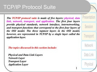
- 1. 1 TCP/IP Protocol Suite The TCP/IP protocol suite is made of five layers: physical, data link, network, transport, and application. The first four layers provide physical standards, network interface, internetworking, and transport functions that correspond to the first four layers of the OSI model. The three topmost layers in the OSI model, however, are represented in TCP/IP by a single layer called the application layer. The topics discussed in this section include: Physical and Data Link Layers Network Layer Transport Layer Application Layer
- 2. 2 OSI and TCP/IP Protocol Stack OSI Model TCP/IP Hierarchy Protocols 7th Application Layer 6th Presentation Layer 5th Session Layer 4th Transport Layer 3rd Network Layer 2nd Link Layer 1st Physical Layer Application Layer Transport Layer Network Layer Link Layer Link Layer : includes device driver and network interface card Network Layer : handles the movement of packets, i.e. Routing Transport Layer : provides a reliable flow of data between two hosts Application Layer : handles the details of the particular application
- 3. Packet Encapsulation The data is sent down the protocol stack Each layer adds to the data by prepending headers 22Bytes 20Bytes 20Bytes 4Bytes 64 to 1500 Bytes
- 4. IP-IPV4 Datagram Vers Header Len Types Of Service Datagram Length(bytes) 16-bit Identifier Flags 13-bits Fragmentation Offset Time-to-Live Protocol Header Checksum 32-bit Source IP Address 32-bit Destination IP Address Options(if Any)... Data... 0 4 8 16 19 24 31 Field Purpose Vers IP version number Header Len Length of IP header (4 bits) TOS Type of Service T. Length Length of entire datagram Ident. IP datagram ID (for frag/reassembly) Flags Don’t/More fragments Frag Off Fragment Offset Field Purpose TTL Time To Live - Max # of hops Protocol Higher level protocol (1=ICMP, 6=TCP, 17=UDP) Checksum Checksum for the IP header Source IA Originator’s Internet Address Dest. IA Final Destination Internet Address Options Source route, time stamp, etc. Data... Higher level protocol data
- 5. Cont….Version No: These 4 bit specify the IP protocol version of the data gram, By looking into datagram version, the routers can determine how to interpret the remainder of the IP datagram . Header length: These 4 bits are needed to determine where IP datagram the actually begins. Types of service: Type of service bits were included in IPV4 header r to allow different types of IP datagram ( for example, datagram particulalarly requiring Low Delay, High throughput , or reliability) to be distinguished from each other. Data gram length: This is total length of the IP datagram(header plus data)measured in bytes . Since this field is 16 bits long, theoretically max size of IP datagram is 65,535 bytes Identifier, flag, fragmentation offset: •Identification:IP datagram ID (for frag/reassembly) •Flags: Don’t/More fragments •Frag. Off: Fragment Offset Time-to-live: TTL field is included to ensure that datagram do not circulate forever in the network. This field is decremented by 1each time the data gram is processed by the routers. If TTL field is reaches to 0, the datagram must be dropped. Protocol: This field is used only when an IP datagram reaches to its final destination. The value of this field indicates the specific transport-layer protocol to which the data portion of this IP datagram should be passed Header checksum: The header checksum aids a router in detecting bits errors in a receiving IP Datagram. Source & destination IP addresses: When a source creates a datagram, it inserts its IP address into the source IP address field and inserts the address of the ultimate destination into destination IP address field. Often the source host determine the destination address via a DNS lookup. Option: The option fields allow an IP header to be executed. Data(Payload): Data field of IP datagram contains the transport-layer segments(TCP or UDP) to be delivered to the destination, However, the data field can carry other types of data, such as ICMP messages
- 6. Address Resolution • Address resolution is the mapping of one address to another • It is generally a mapping between a Layer 3 network address (logical) and a Layer 2 hardware address (physical) • The reverse process is also address resolution
- 7. Address Resolution • Address resolution is accomplished in one of the following ways: – Table lookup is a rarely used method of address resolution – Closed-form computation is only used in very specific networks and is time consuming to configure – Dynamic message exchange is the most common and involves an exchange of information between two hosts
- 8. Address Resolution • Address Resolution Protocol (ARP) is used when an IP host has a known destination IP address (Layer 3) and it needs to retrieve the corresponding Layer 2 MAC address from the destination host • The ARP cache is used to further reduce the need for broadcasts by storing the IP-to- MAC mapping in memory for a specified duration
- 9. 9 Figure 1: ARP operation
- 10. Address Resolution The ARP Process: Client A sends out an ARP broadcast All clients receive and process the broadcast frame but only Machine B responds Client A receives the response and places Machine B’s MAC address in its ARP cache
- 11. 11 Figure 2: Four cases using ARP