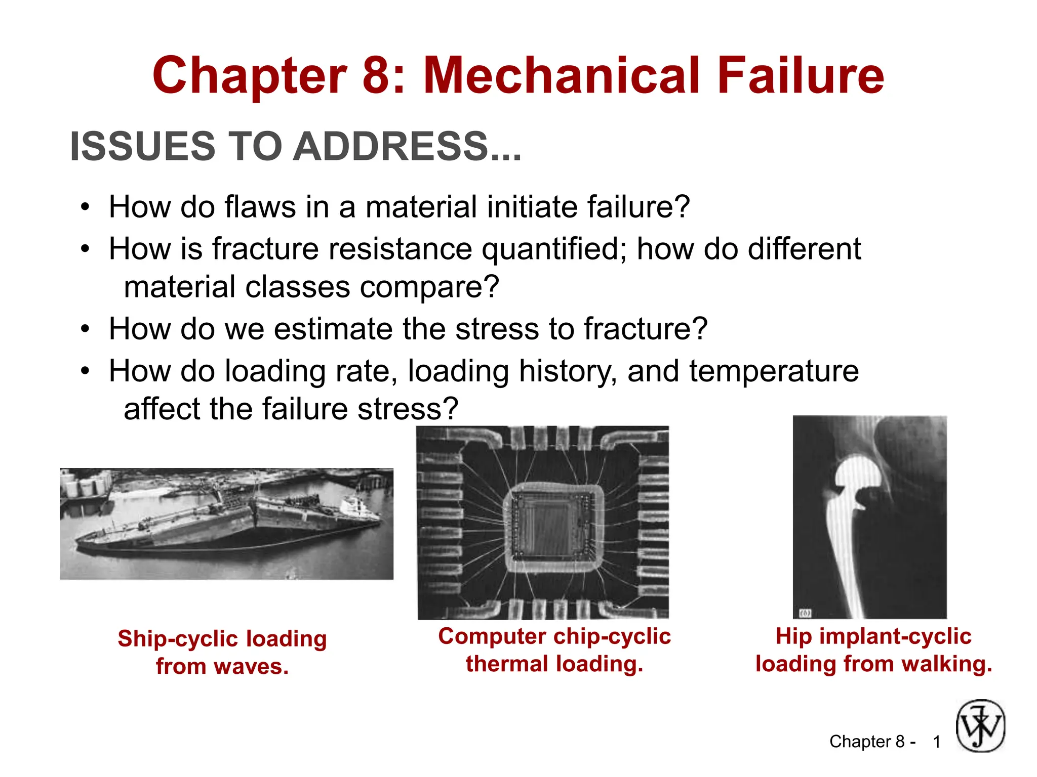
This document summarizes key concepts about mechanical failure from chapter 8, including:
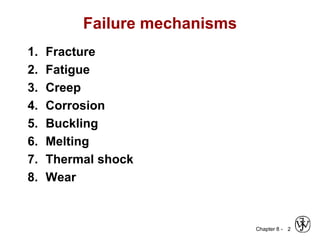
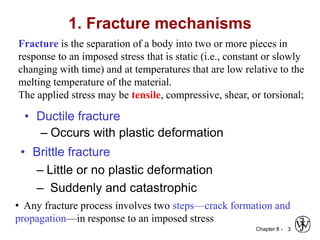
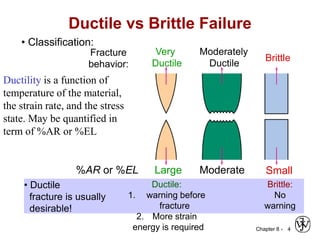
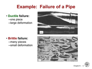
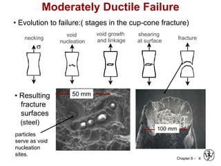
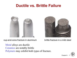
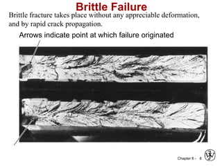
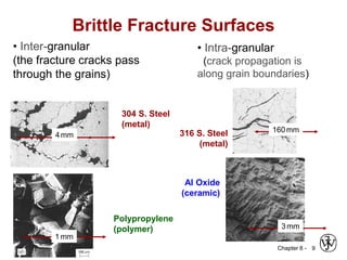
1. It discusses different failure mechanisms like fracture, fatigue, creep, corrosion, and others. It also defines ductile and brittle fracture.
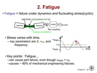
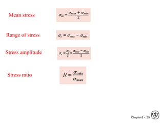
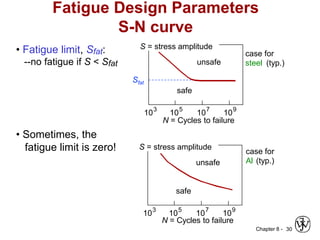
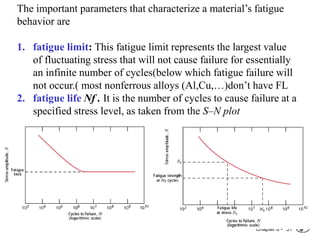
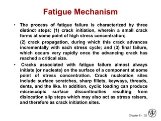
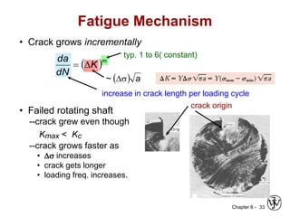
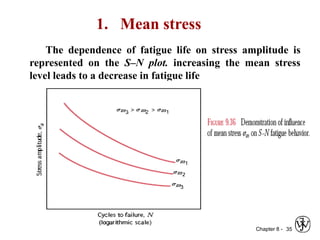
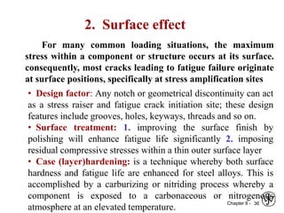
2. Fatigue failure is described as occurring in three stages - crack initiation, propagation, and final failure. It is influenced by factors like stress range and mean stress.
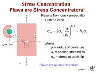
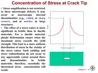
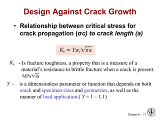
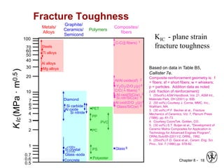
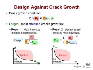
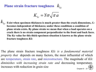
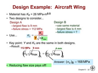
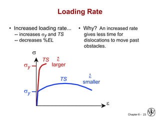
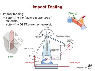
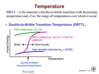
3. Fracture toughness is introduced as a material's resistance to brittle fracture when a crack is present. The influence of loading rate, temperature, and microstructure on failure stress is also covered.