Concept Check 8.1
Citetwo situations in which the possibility of failure is part of
the design of a component or product.
Answer: Several situations in which the possibility of failure is
part of the design of a component or product are as follows:
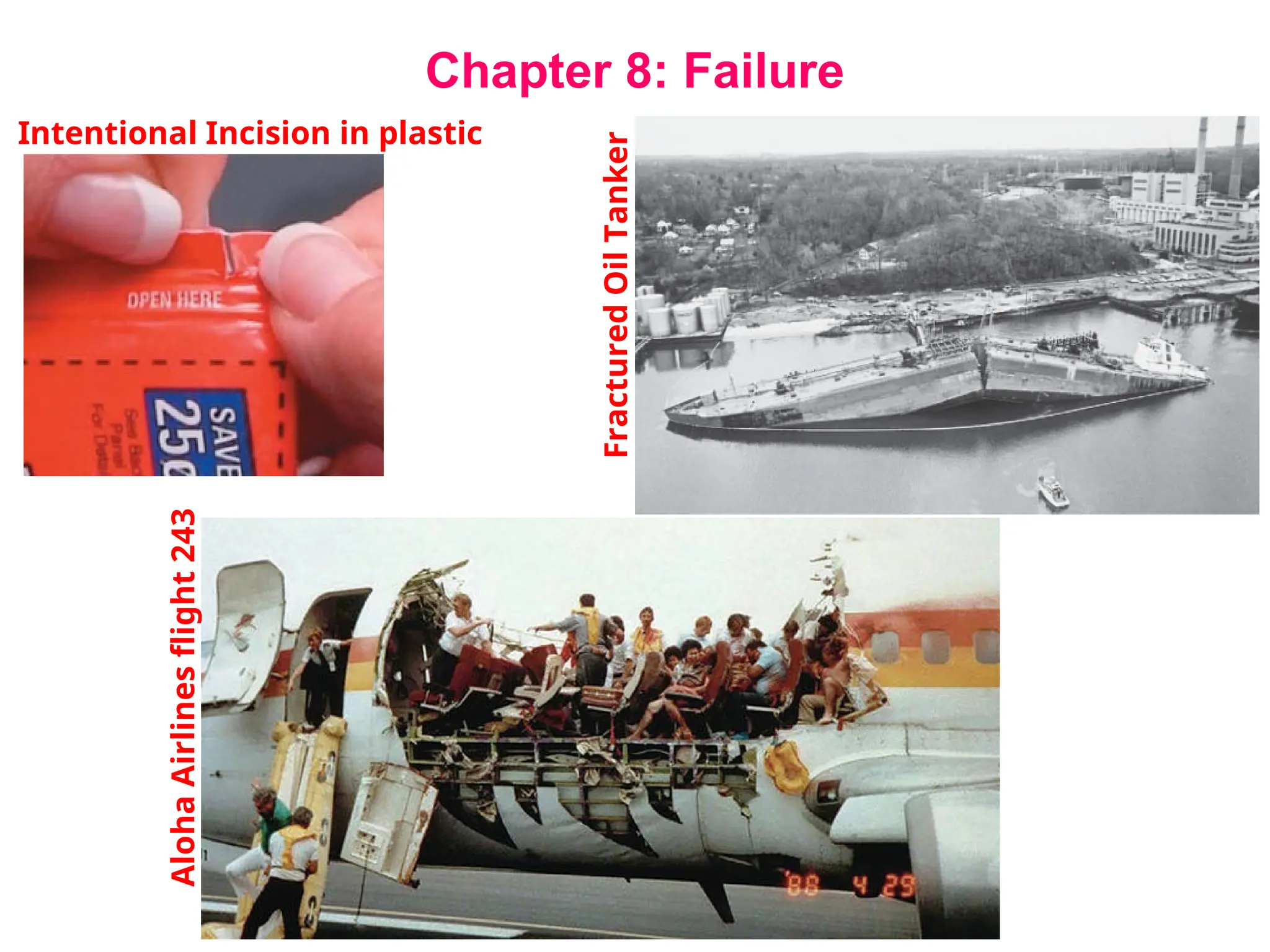
1.The pull tab on the top of aluminum beverage cans
2.Aluminum utility/light poles that reside along freeways—a
minimum of damage occurs to a vehicle when it collides with
the pole.
3.In some machinery components, a shear pin is used to
connect a gear or pulley to a shaft—the pin is designed shear
off before damage is done to either the shaft or gear in an
overload situation
3.
Topics to becovered
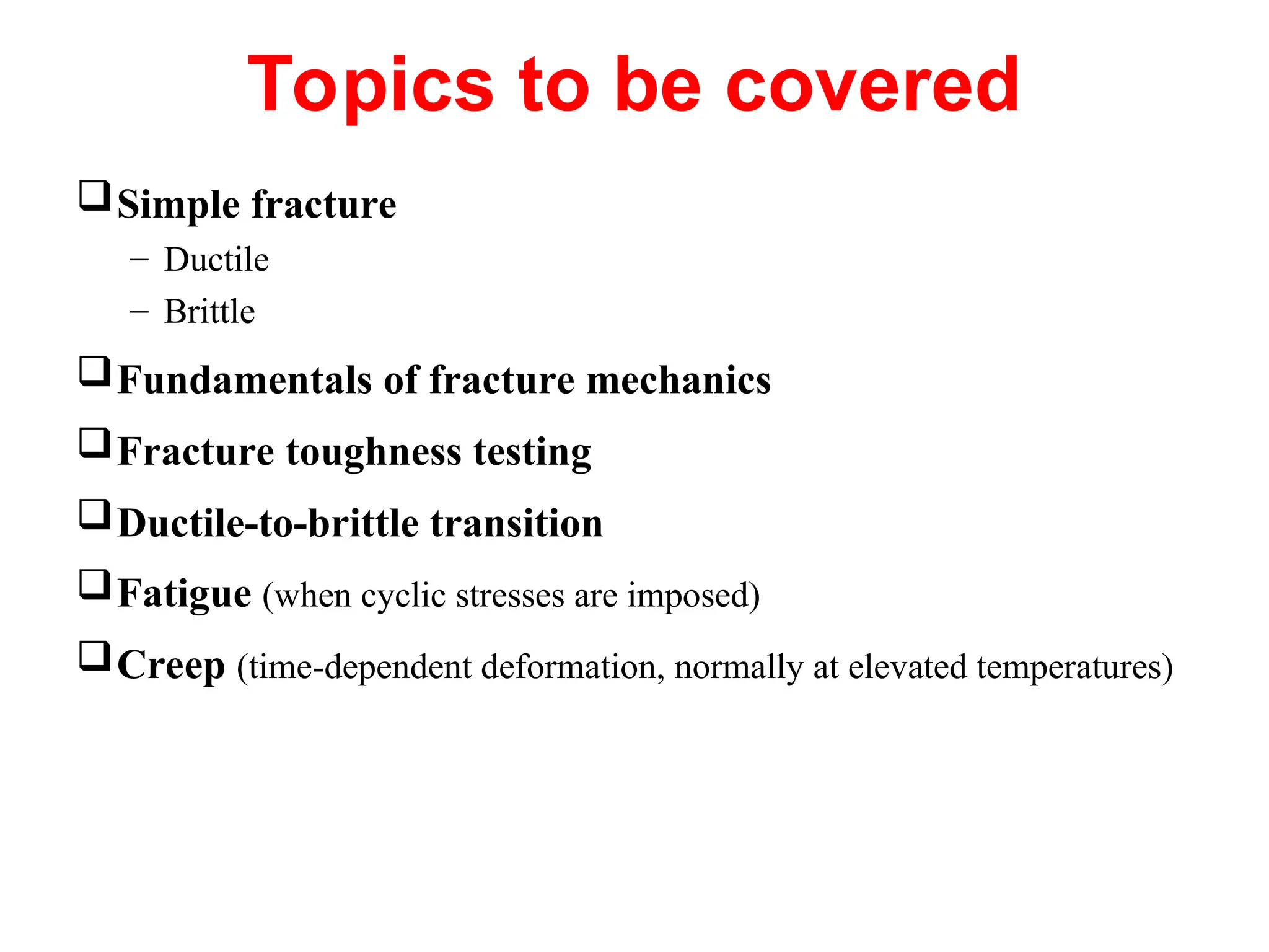
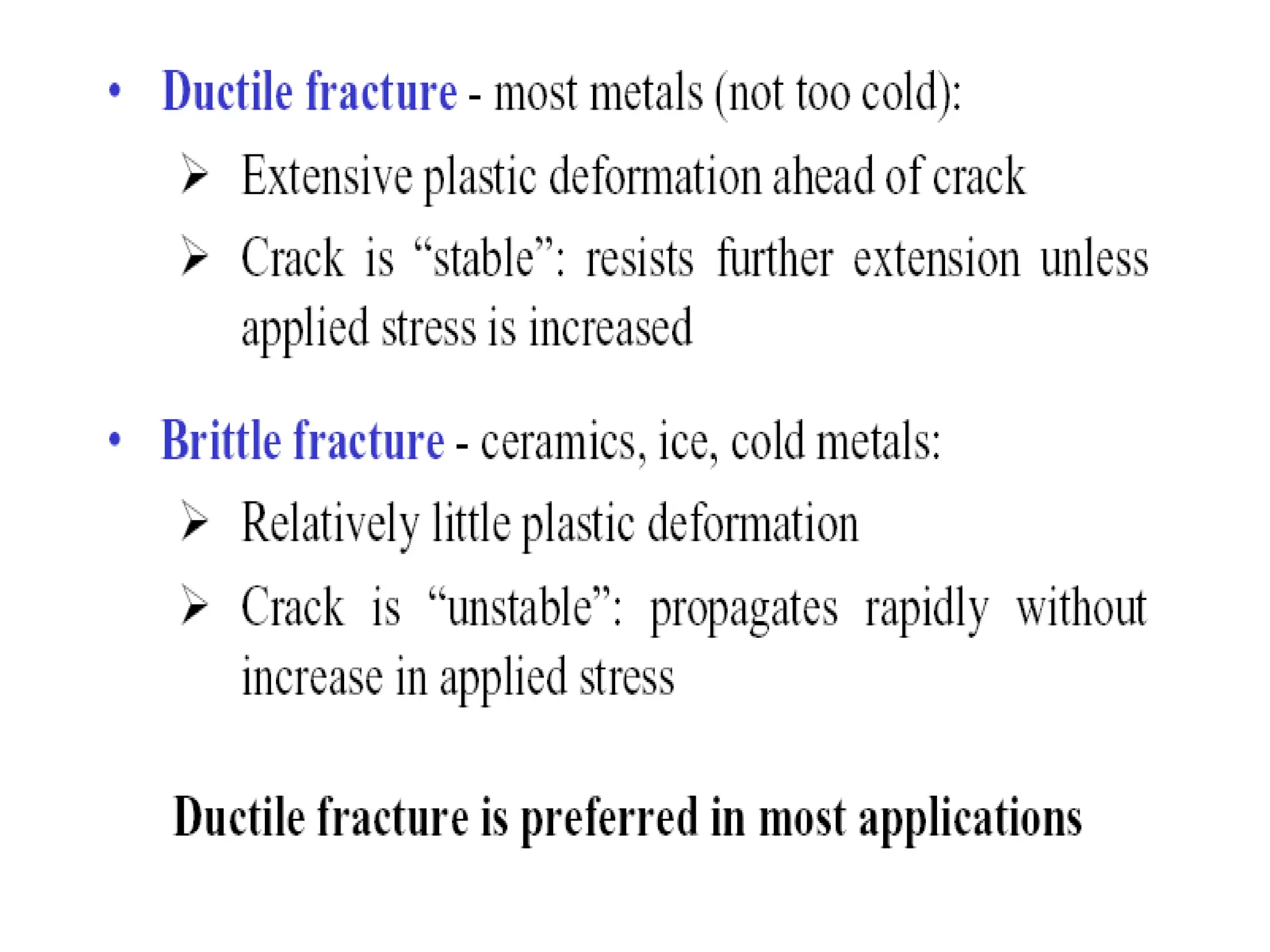
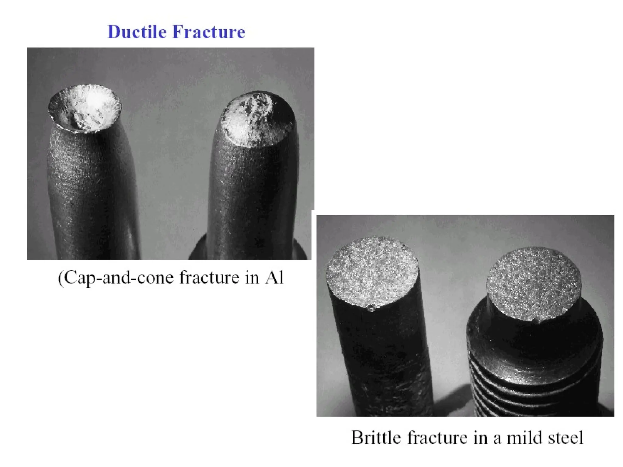
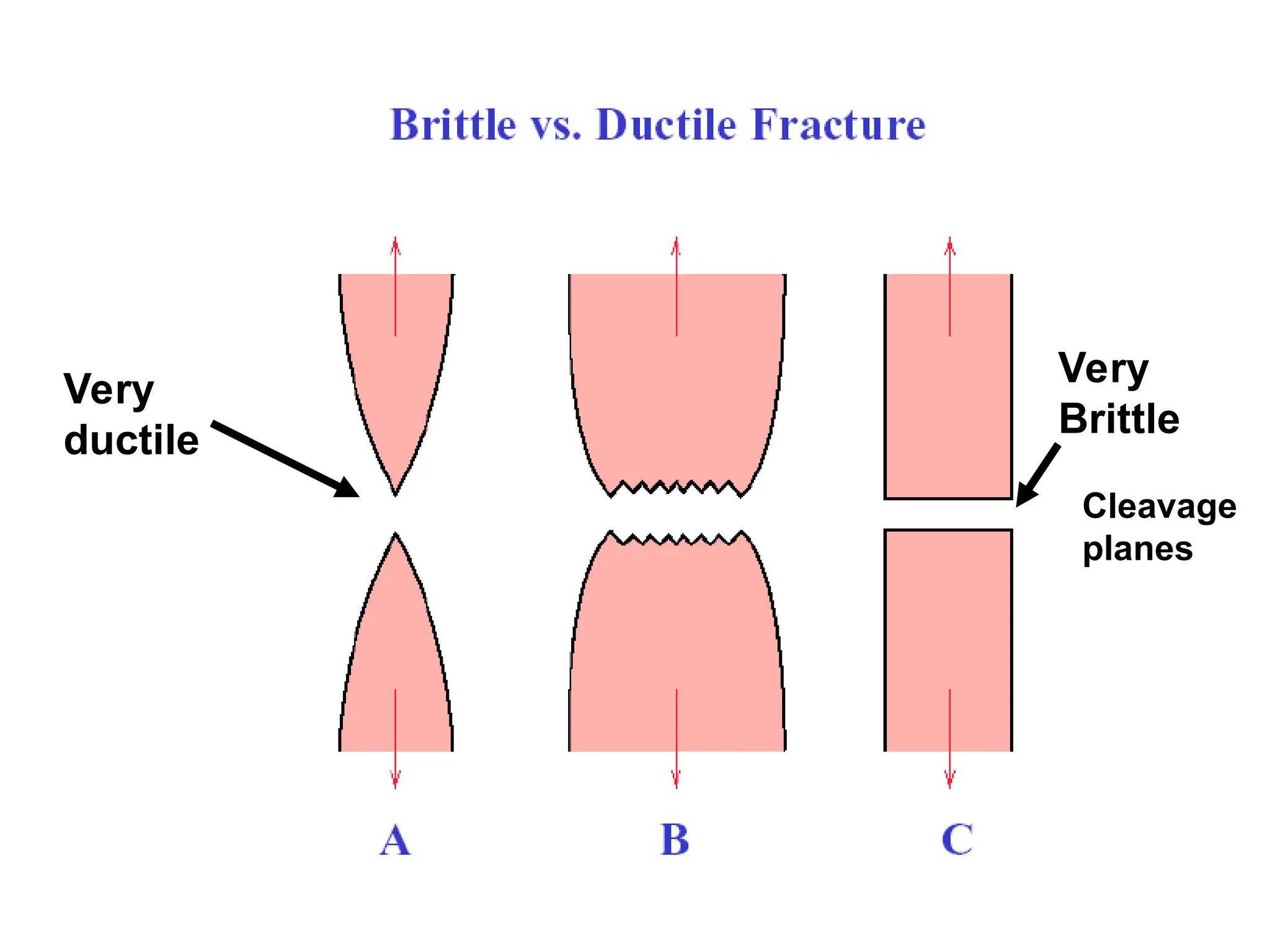
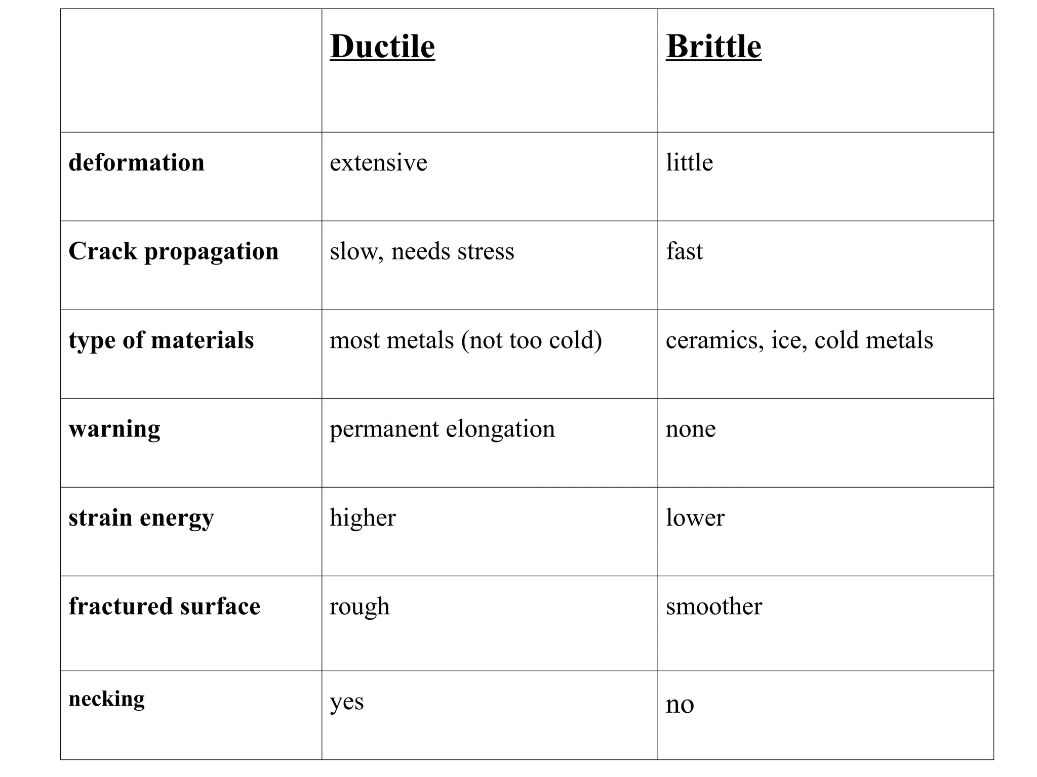
Simple fracture
– Ductile
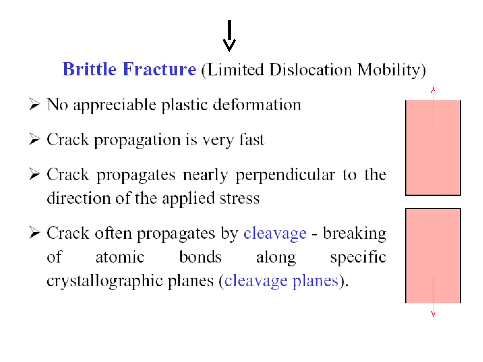
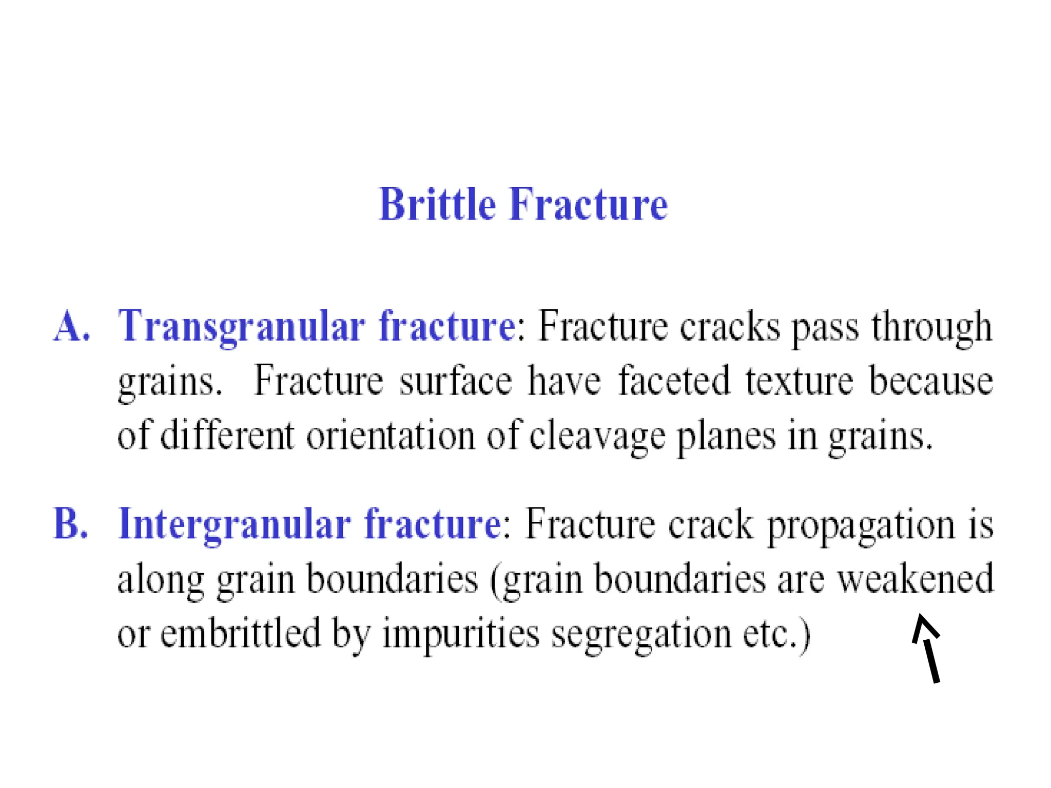
– Brittle
Fundamentals of fracture mechanics
Fracture toughness testing
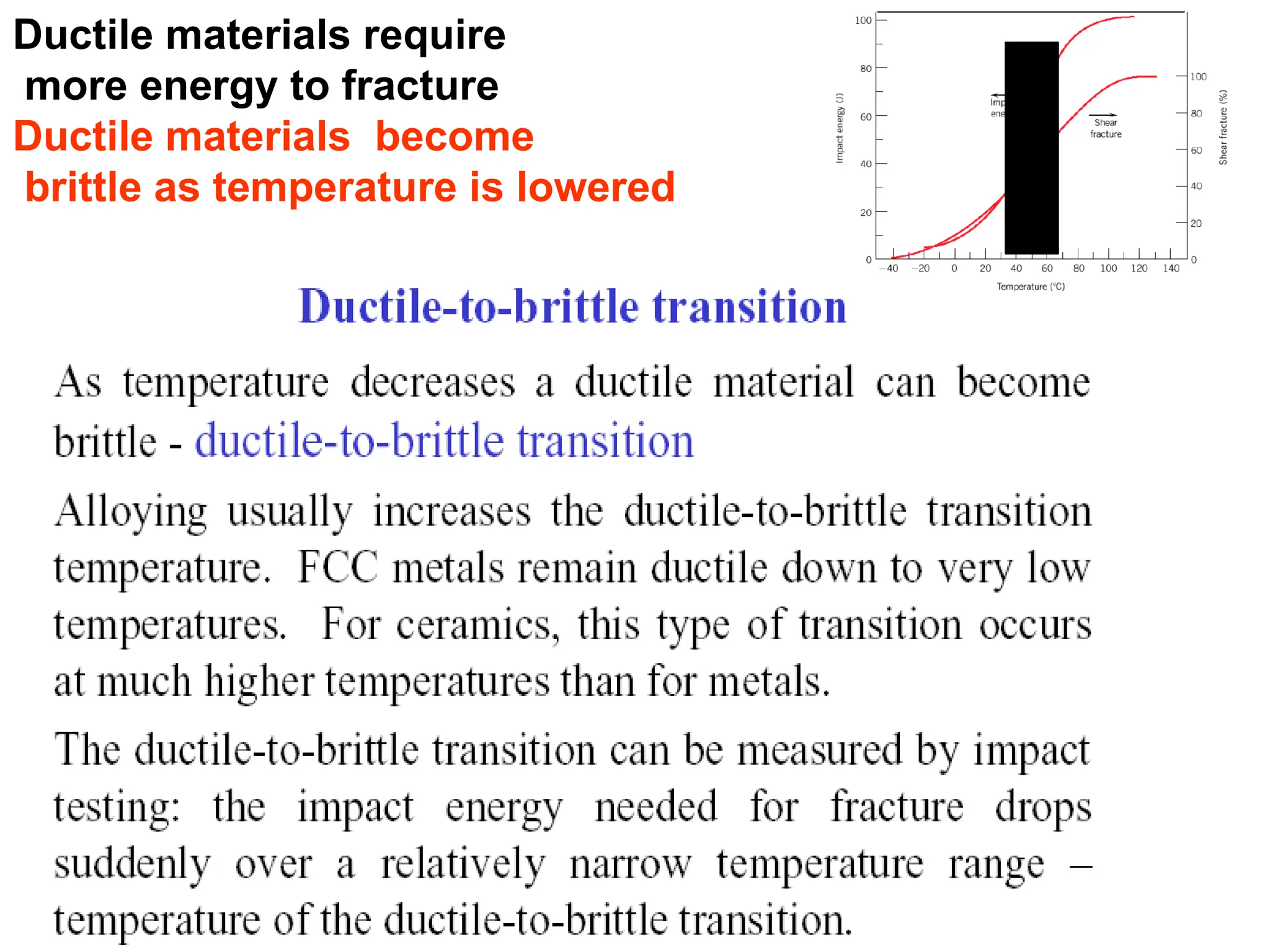
Ductile-to-brittle transition
Fatigue (when cyclic stresses are imposed)
Creep (time-dependent deformation, normally at elevated temperatures)
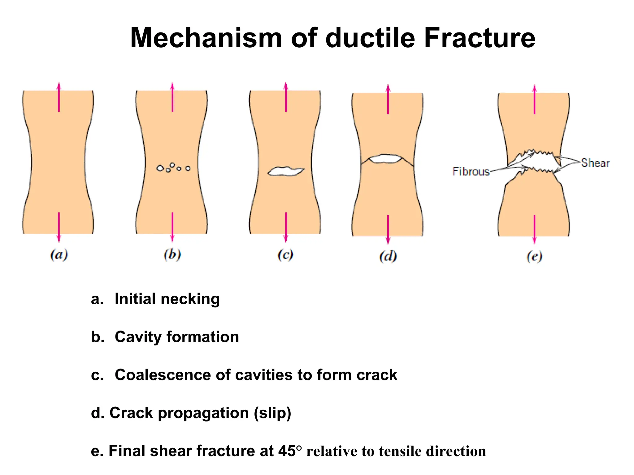
a. Initial necking
b.Cavity formation
c. Coalescence of cavities to form crack
d. Crack propagation (slip)
e. Final shear fracture at 45° relative to tensile direction
Mechanism of ductile Fracture
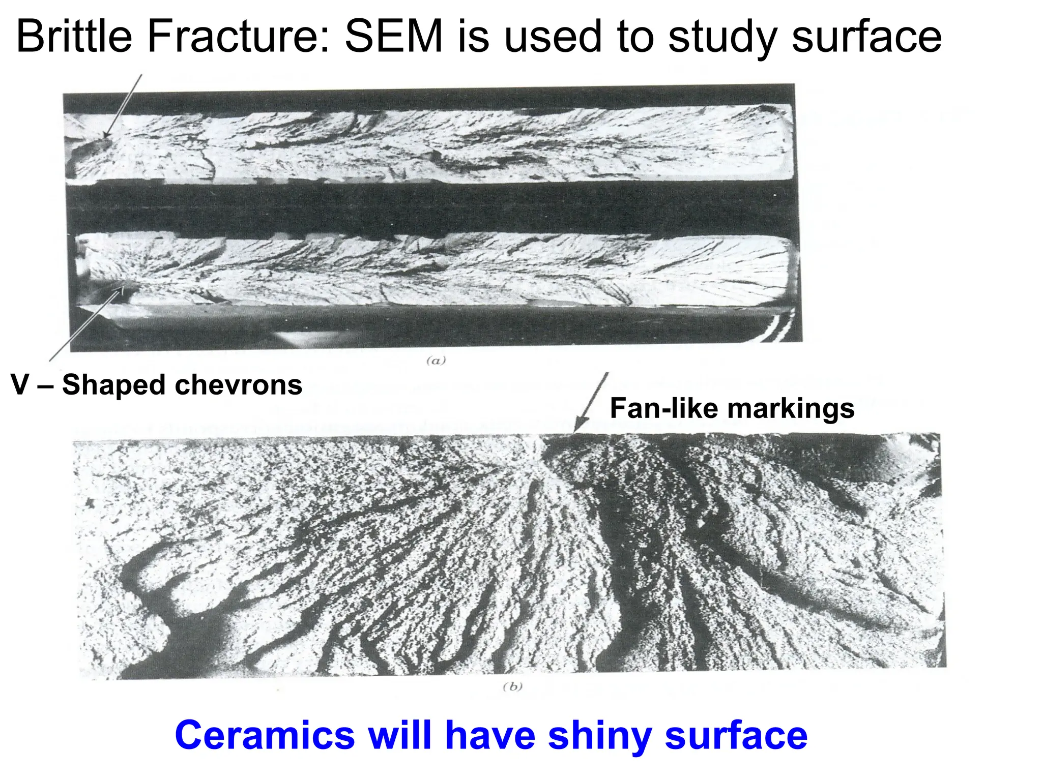
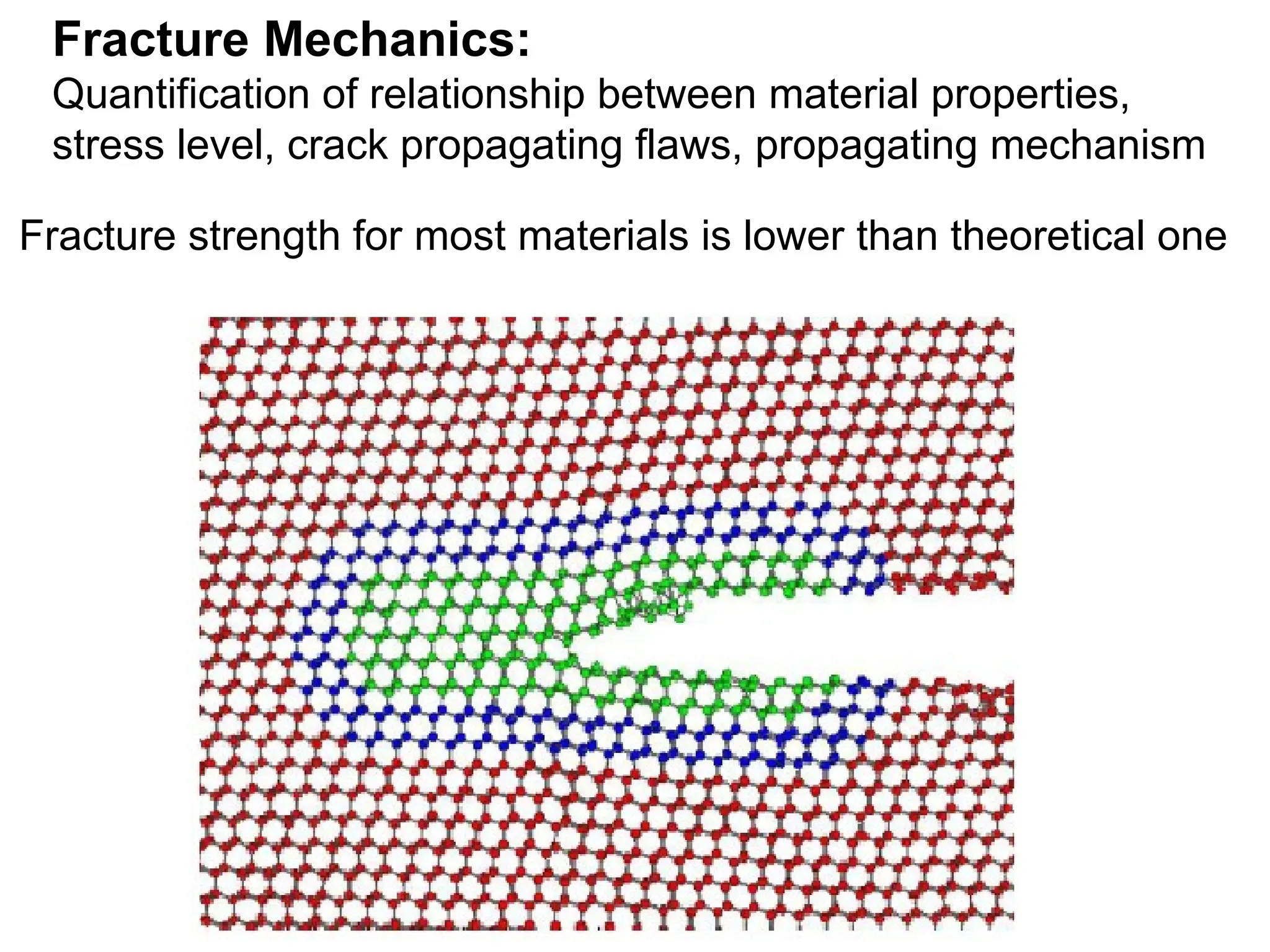
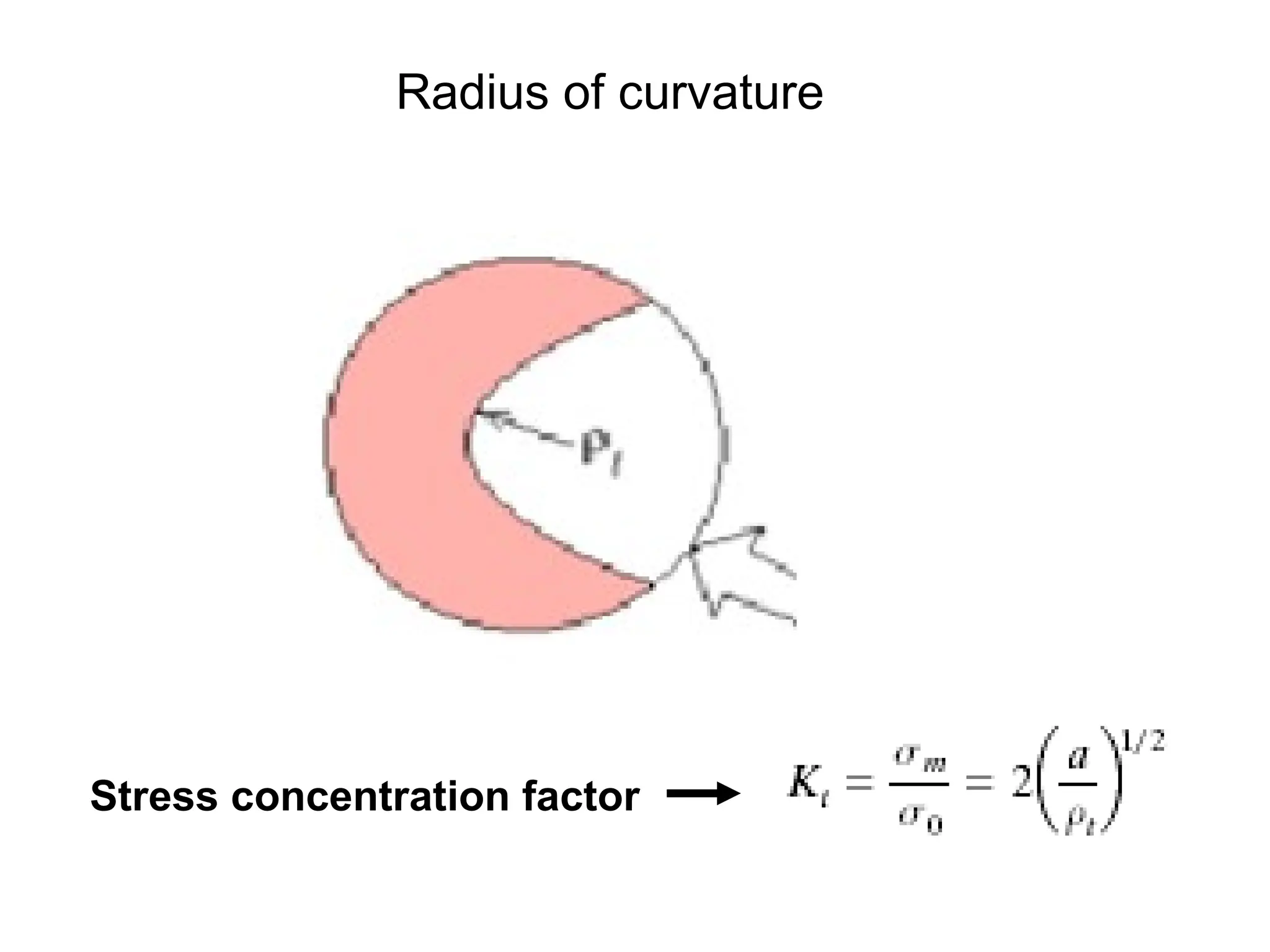
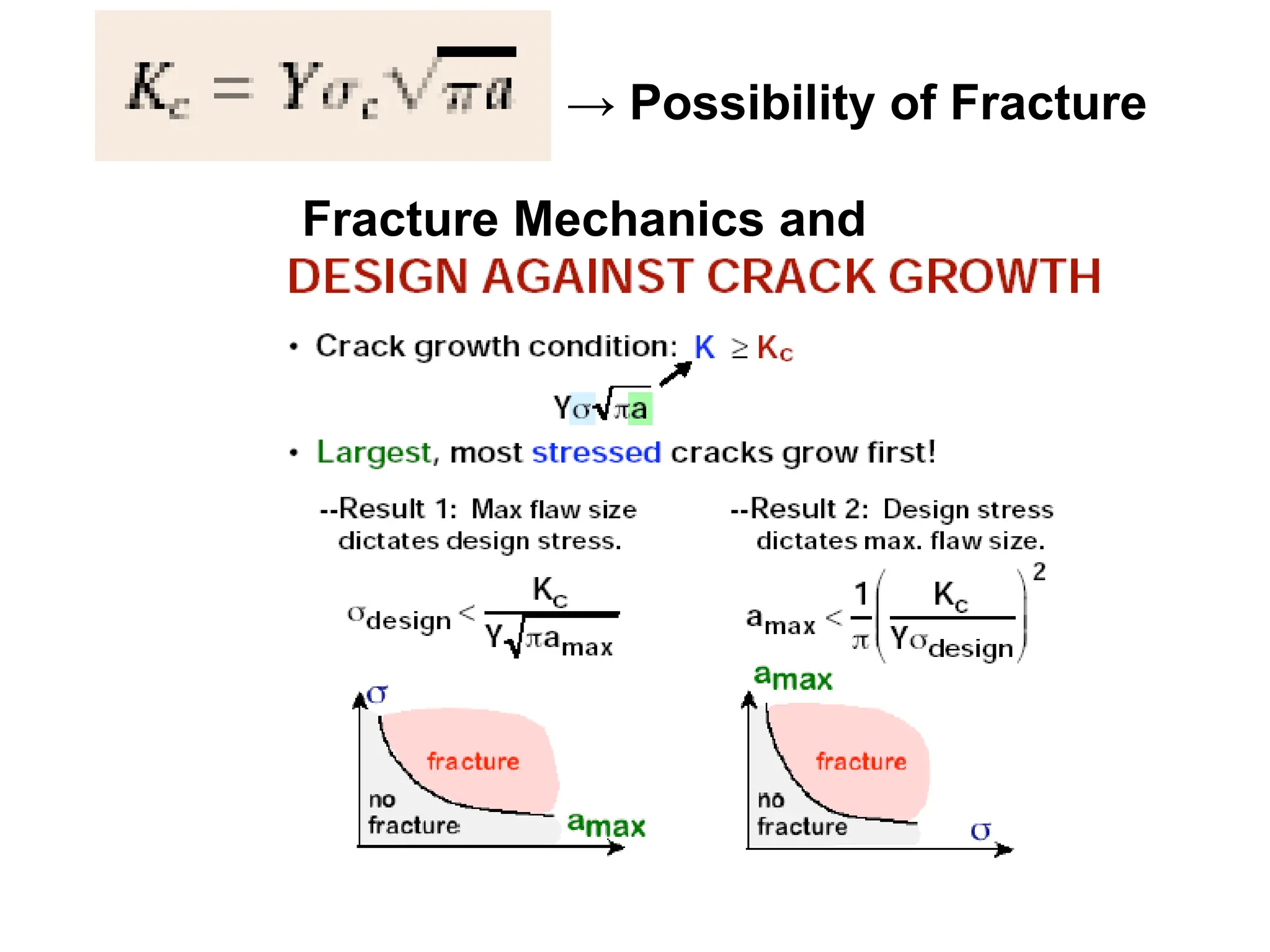
Fracture Mechanics:
Quantification ofrelationship between material properties,
stress level, crack propagating flaws, propagating mechanism
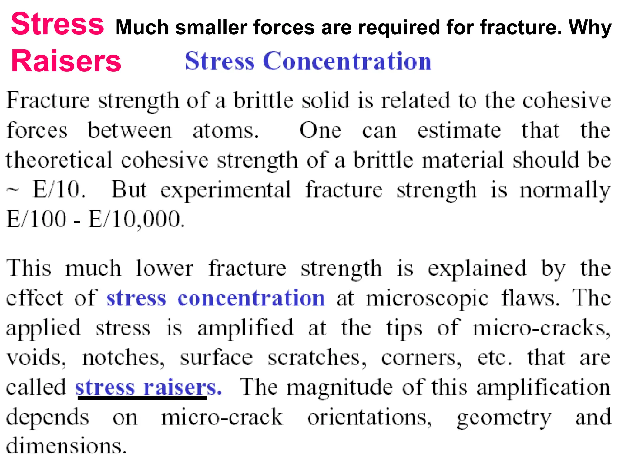
Fracture strength for most materials is lower than theoretical one
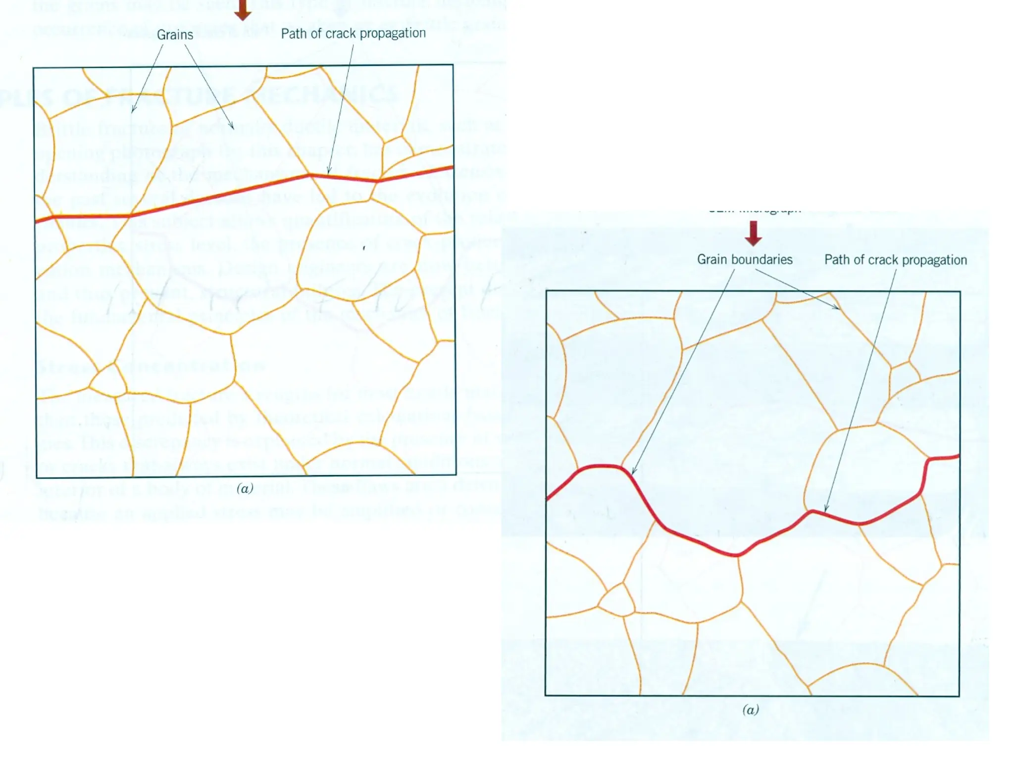
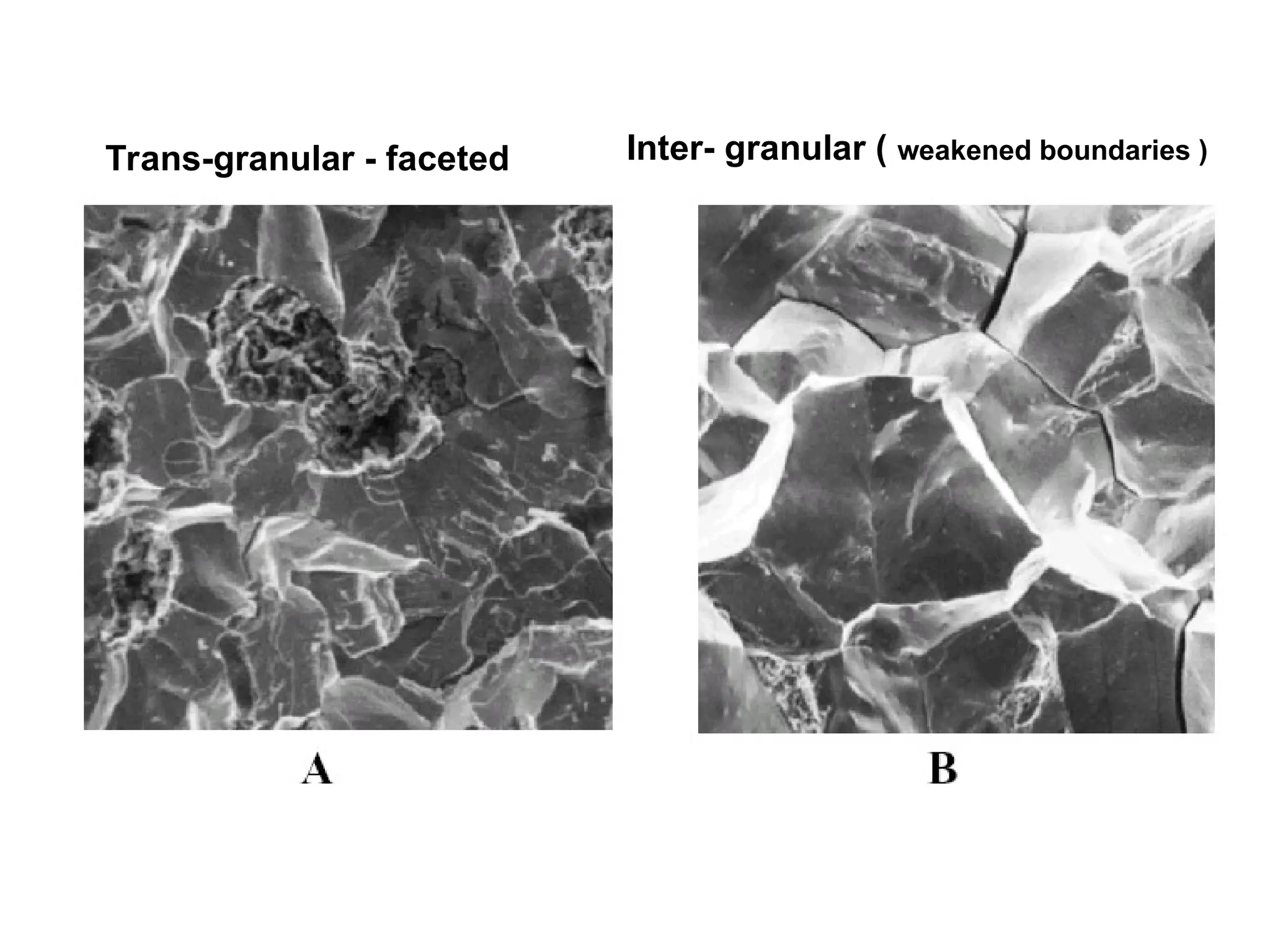
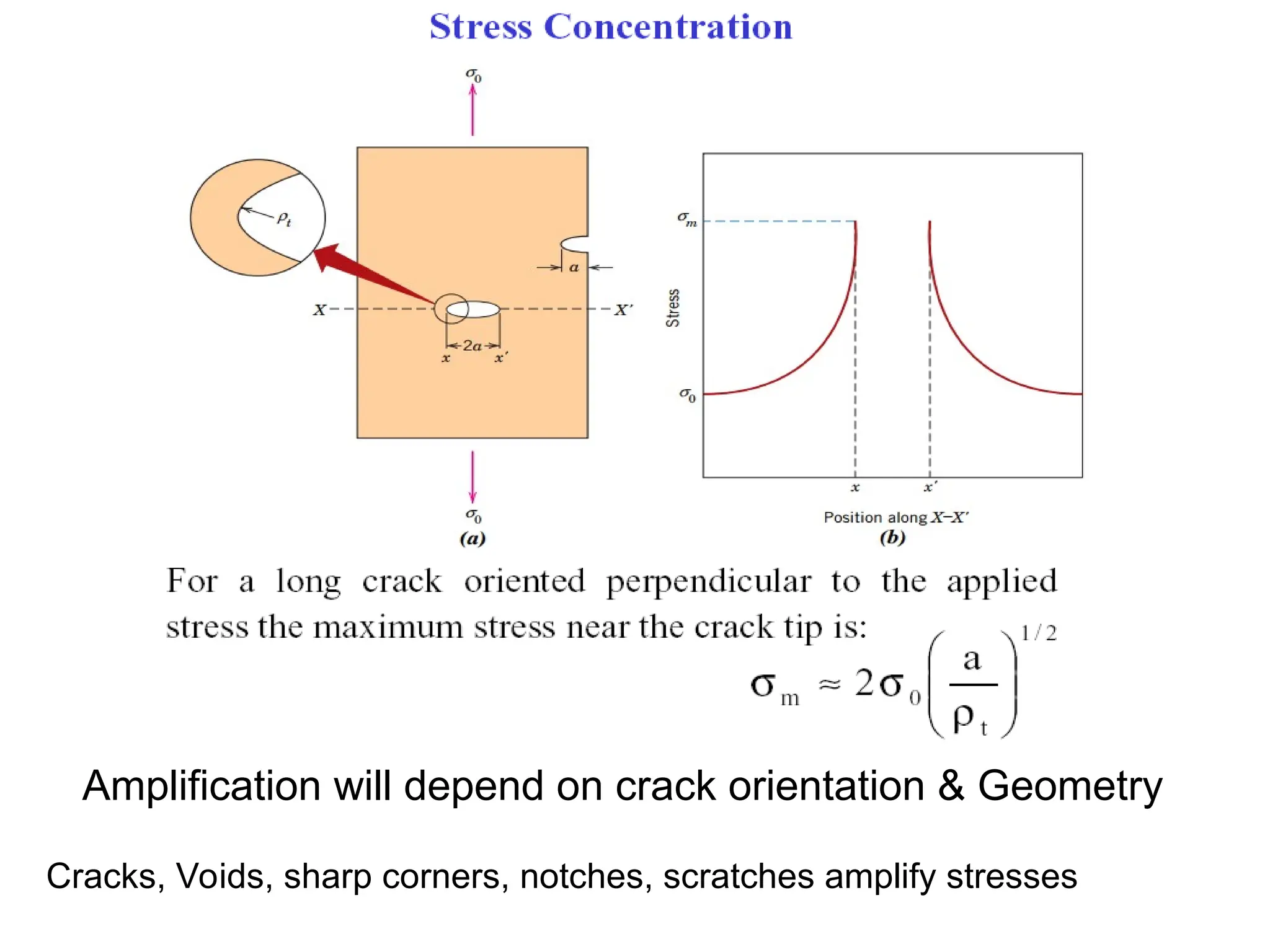
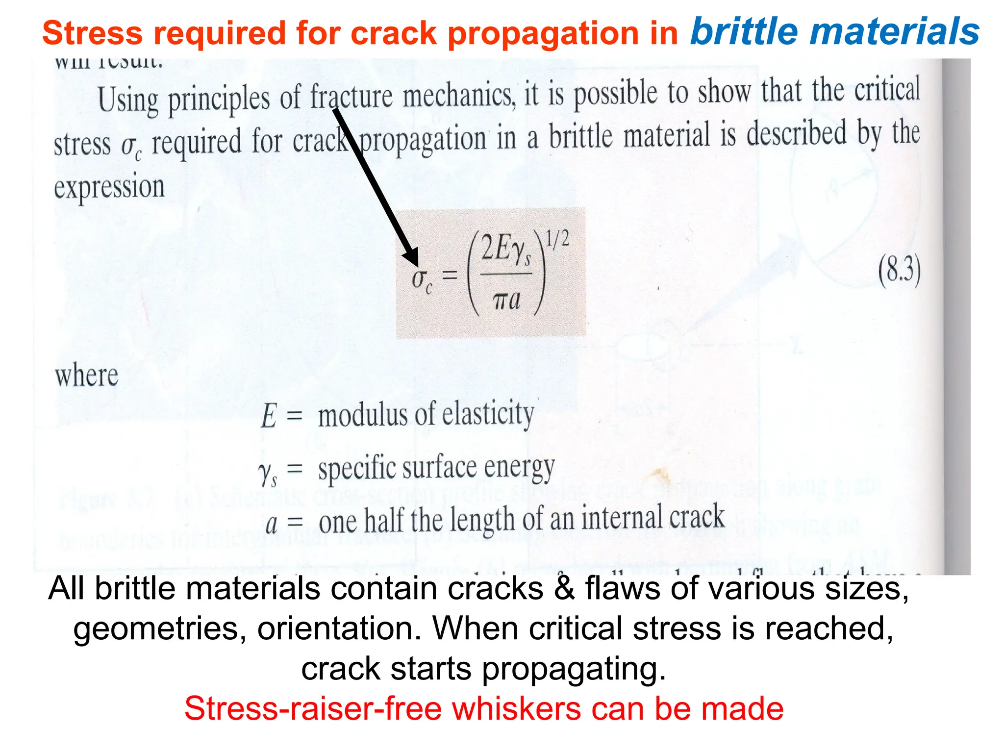
Stress required forcrack propagation in brittle materials
All brittle materials contain cracks & flaws of various sizes,
geometries, orientation. When critical stress is reached,
crack starts propagating.
Stress-raiser-free whiskers can be made
23.
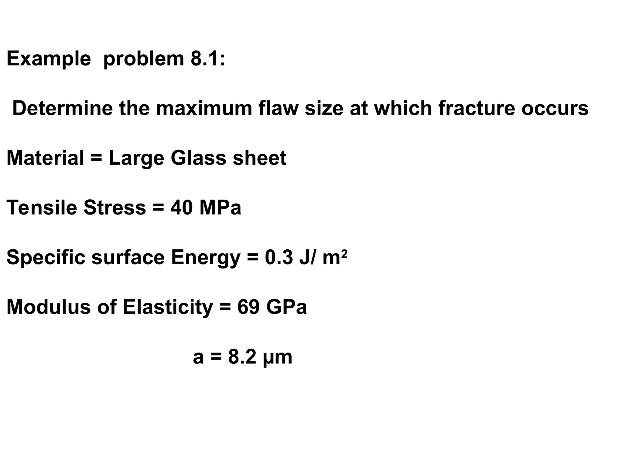
Example problem 8.1:
Determinethe maximum flaw size at which fracture occurs
Material = Large Glass sheet
Tensile Stress = 40 MPa
Specific surface Energy = 0.3 J/ m2
Modulus of Elasticity = 69 GPa
a = 8.2 µm
24.
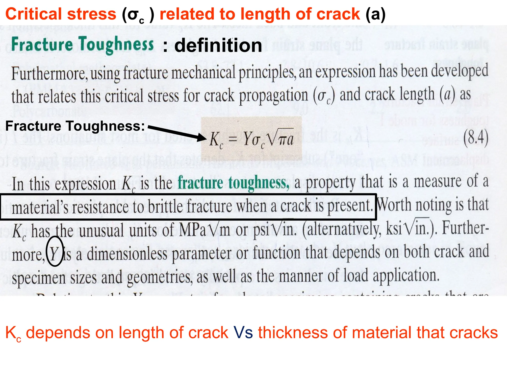
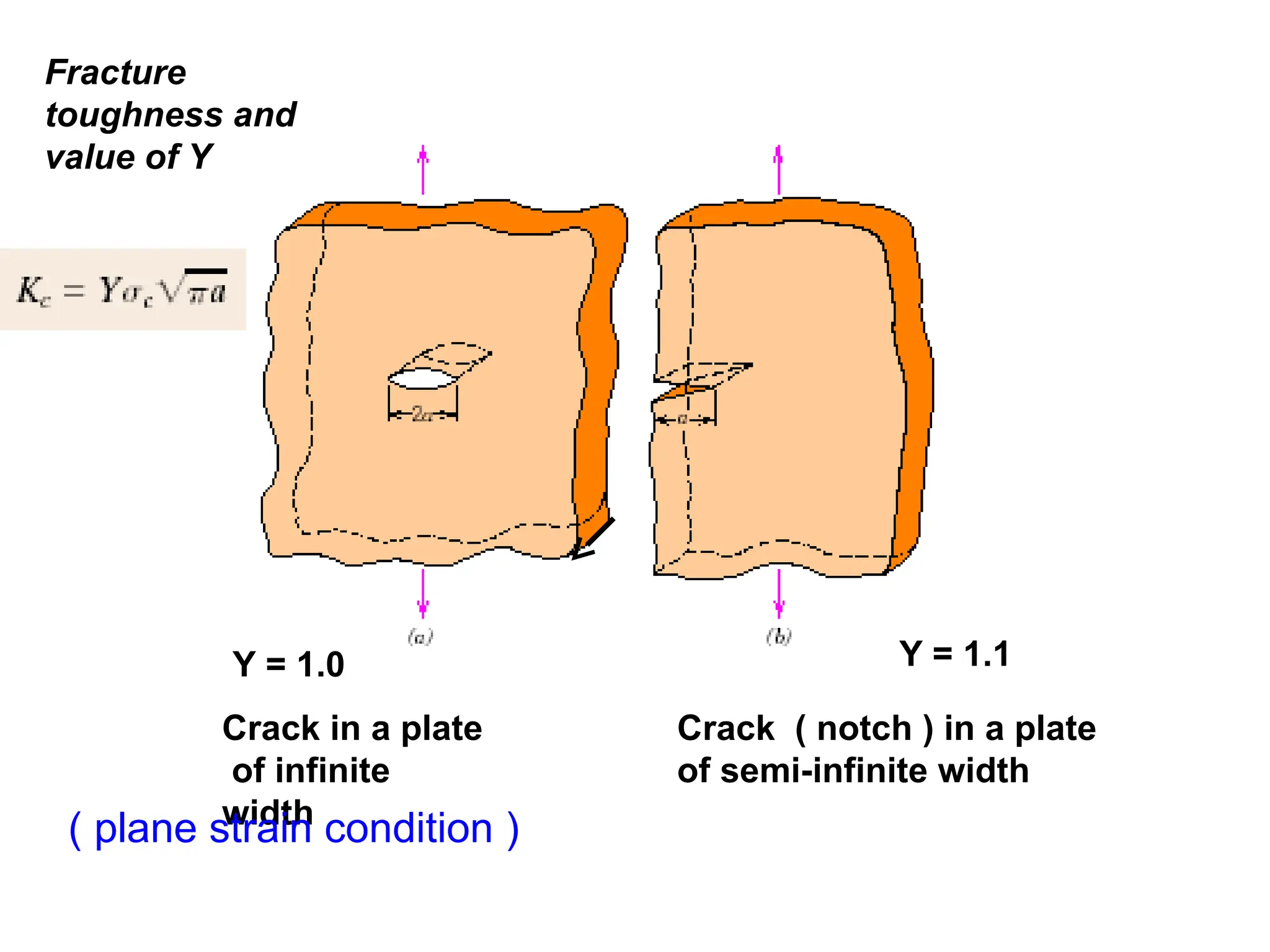
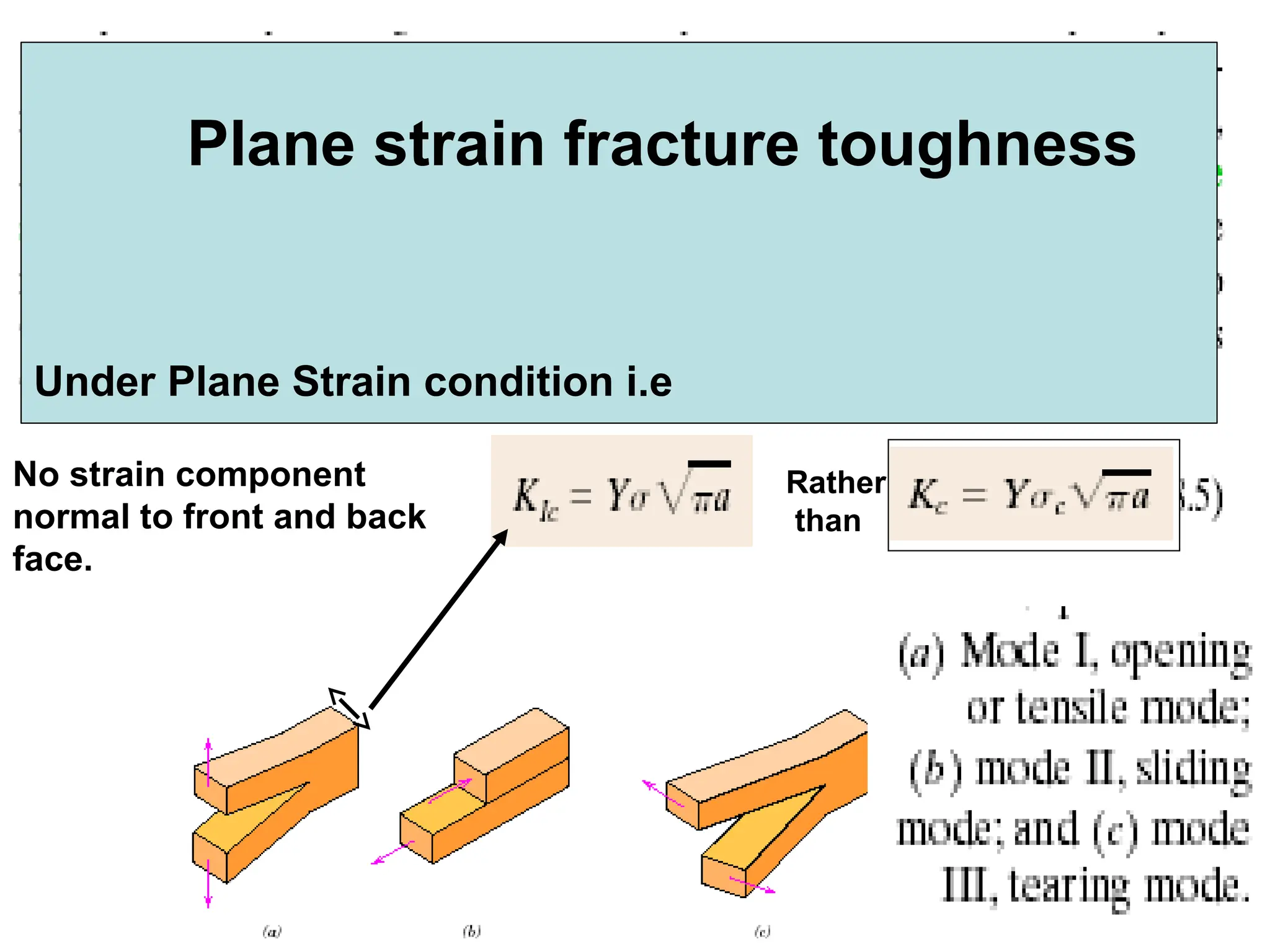
Fracture Toughness:
Critical stress(σc ) related to length of crack (a)
: definition
Kc depends on length of crack Vs thickness of material that cracks
25.
Y = 1.0Y = 1.1
Crack in a plate
of infinite
width
Crack ( notch ) in a plate
of semi-infinite width
Fracture
toughness and
value of Y
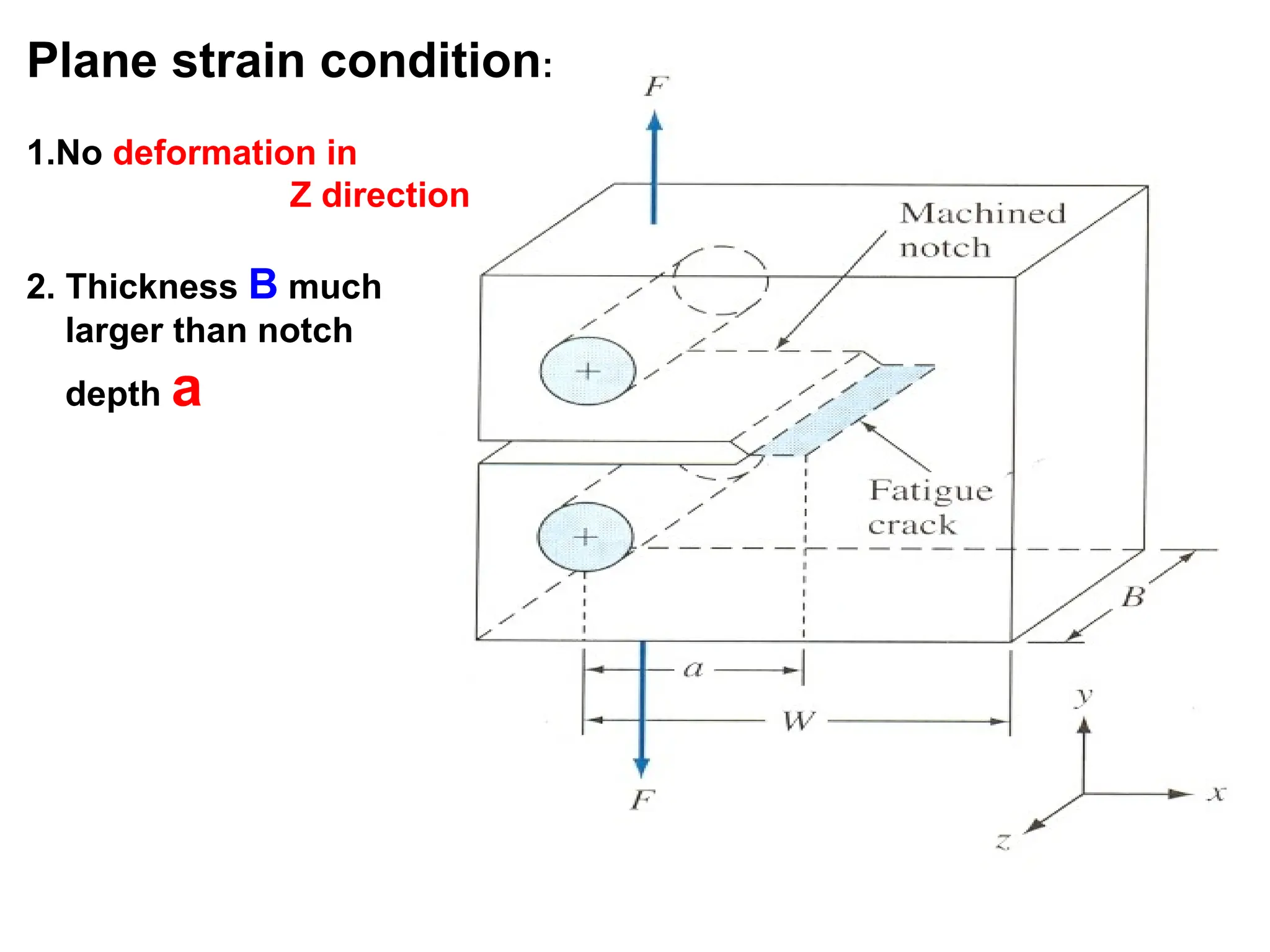
( plane strain condition )
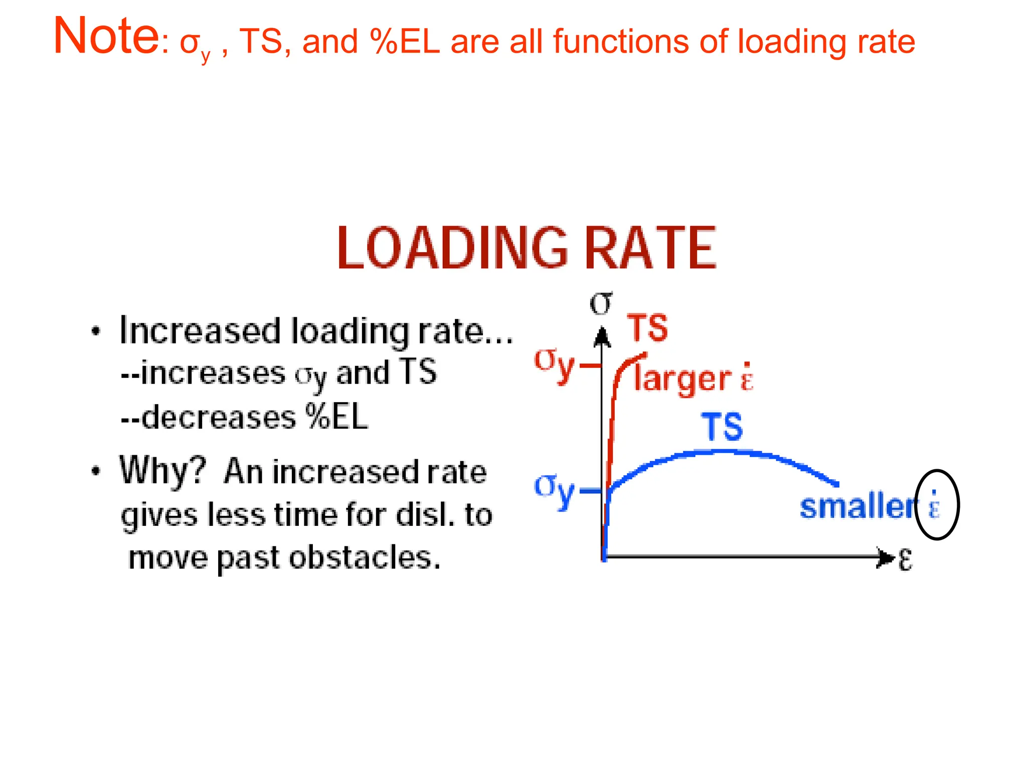
Note: σy ,TS, and %EL are all functions of loading rate
31.
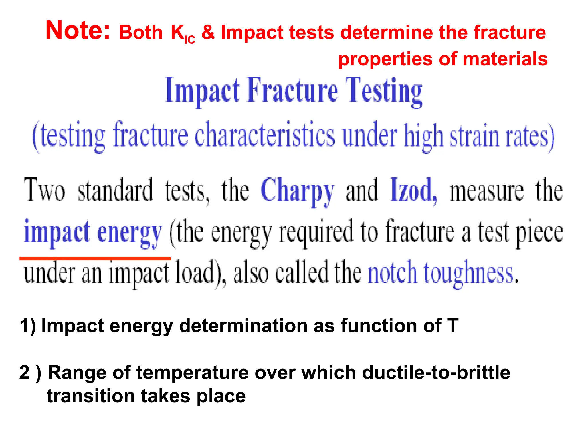
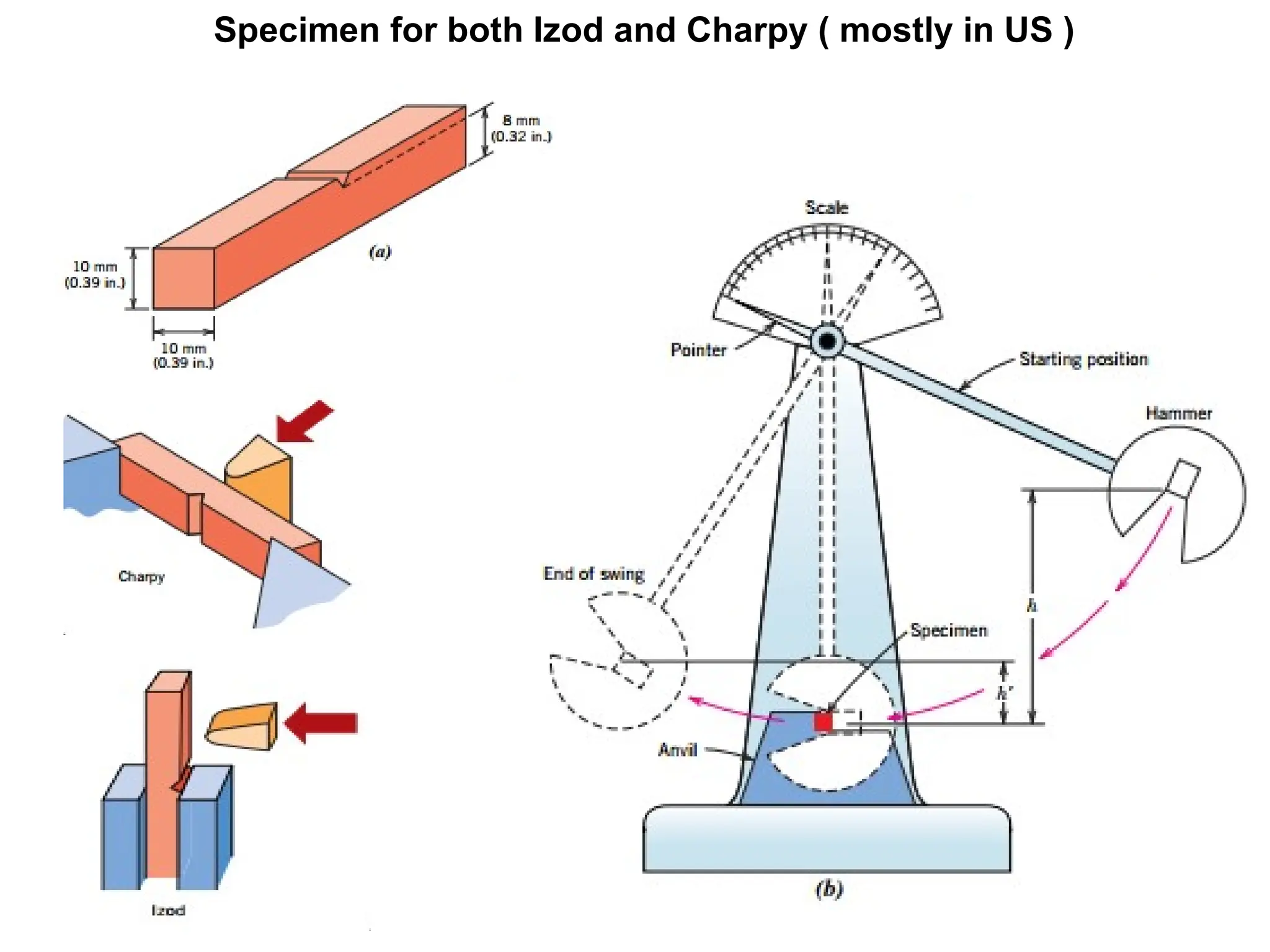
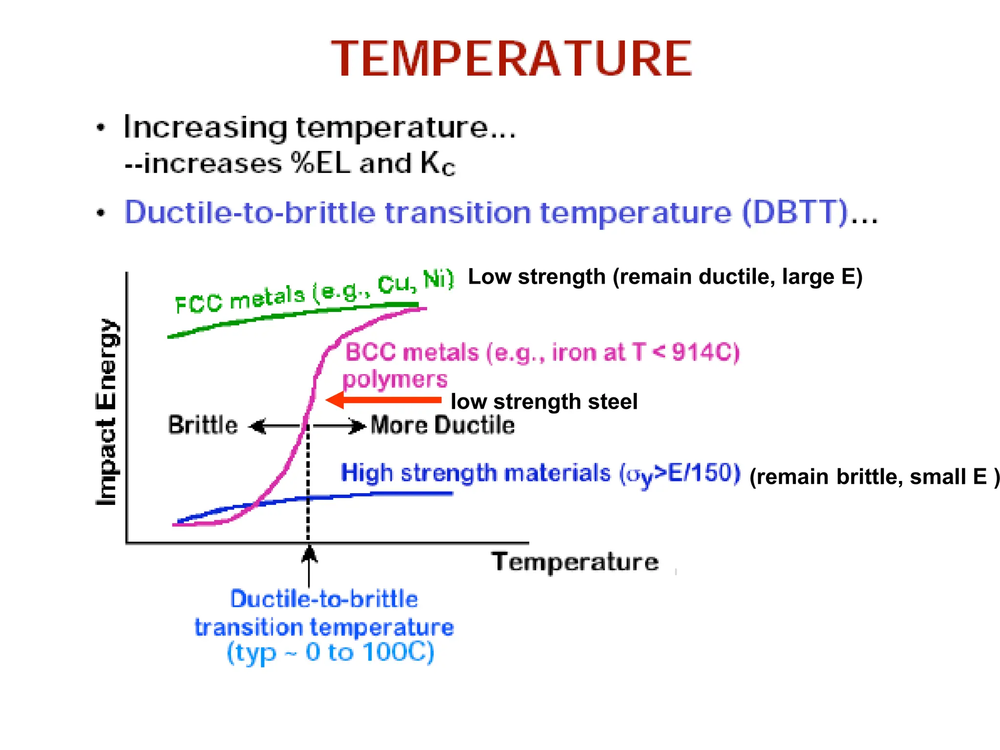
1) Impact energydetermination as function of T
2 ) Range of temperature over which ductile-to-brittle
transition takes place
Note: Both KIC & Impact tests determine the fracture
properties of materials
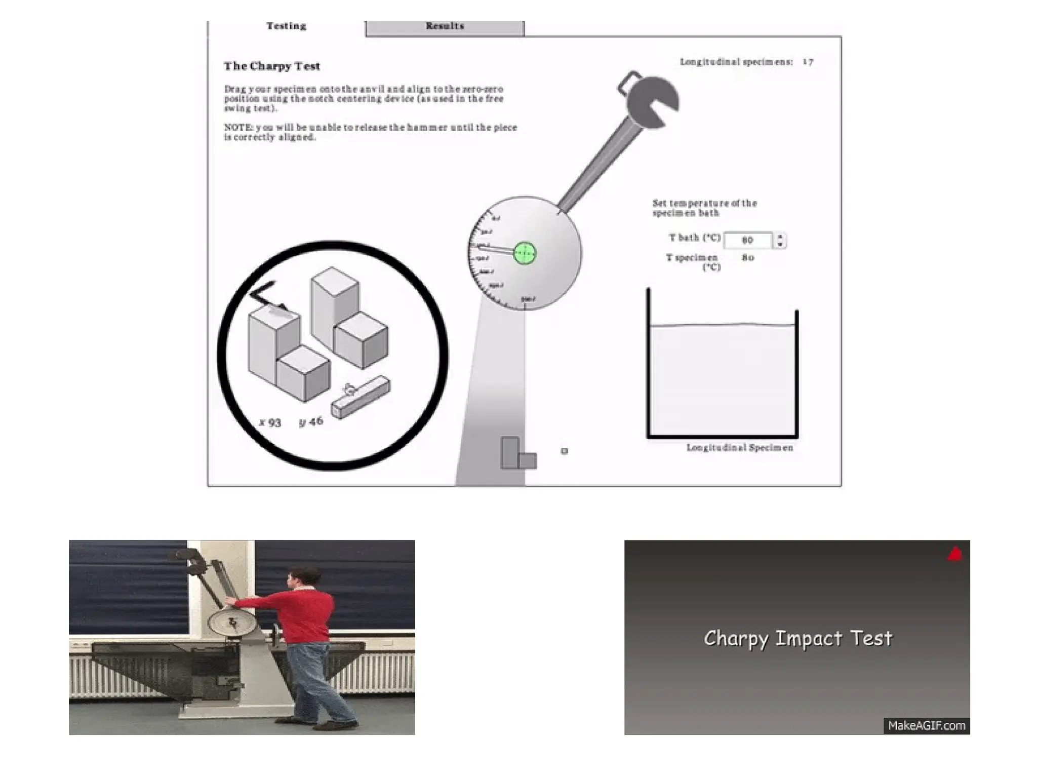
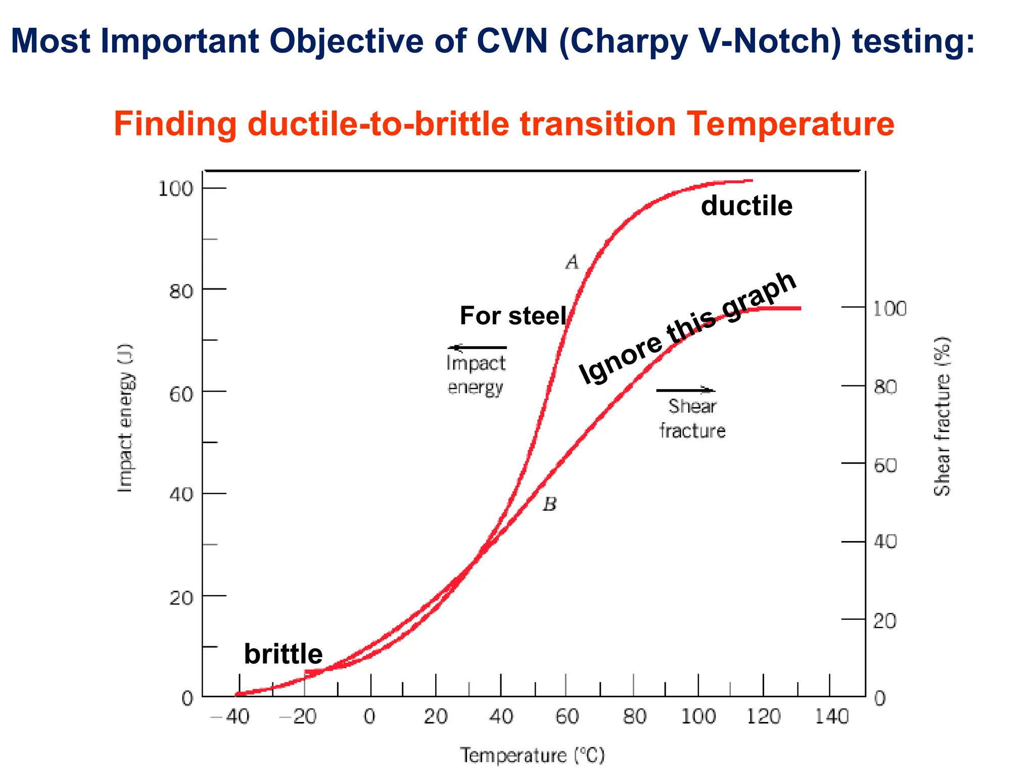
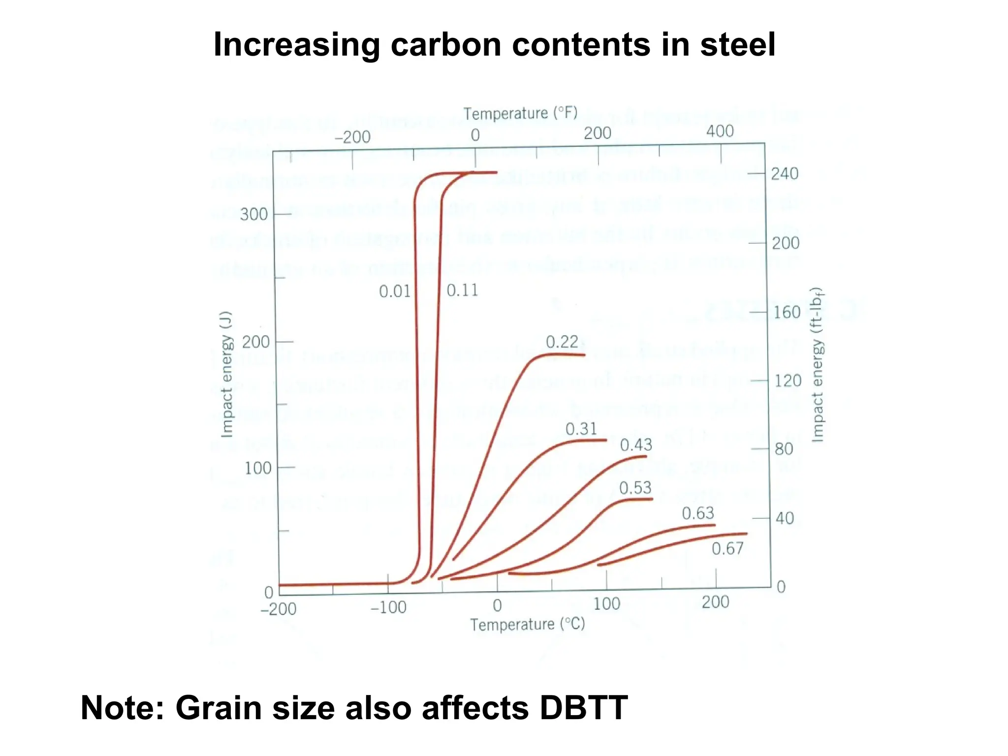
Most Important Objectiveof CVN (Charpy V-Notch) testing:
Finding ductile-to-brittle transition Temperature
For steel
Ignore this graph
brittle
ductile
35.
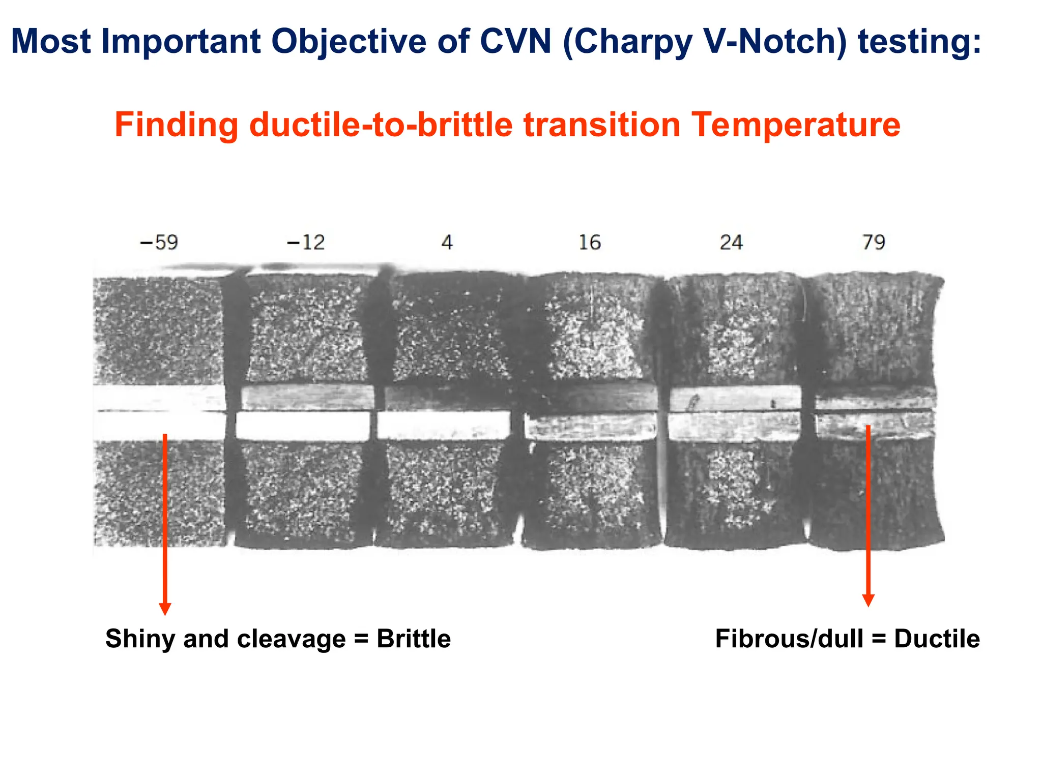
Most Important Objectiveof CVN (Charpy V-Notch) testing:
Finding ductile-to-brittle transition Temperature
Shiny and cleavage = Brittle Fibrous/dull = Ductile
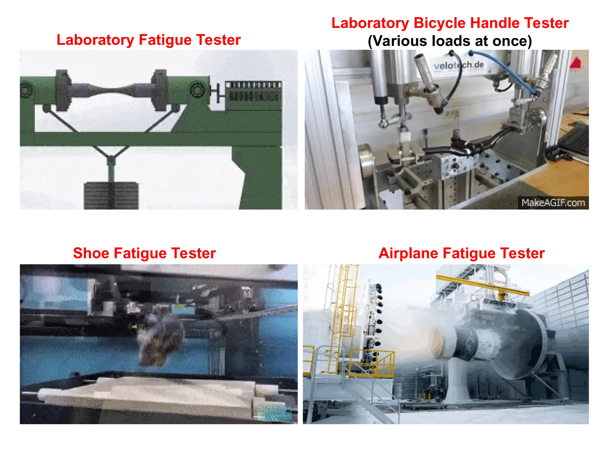
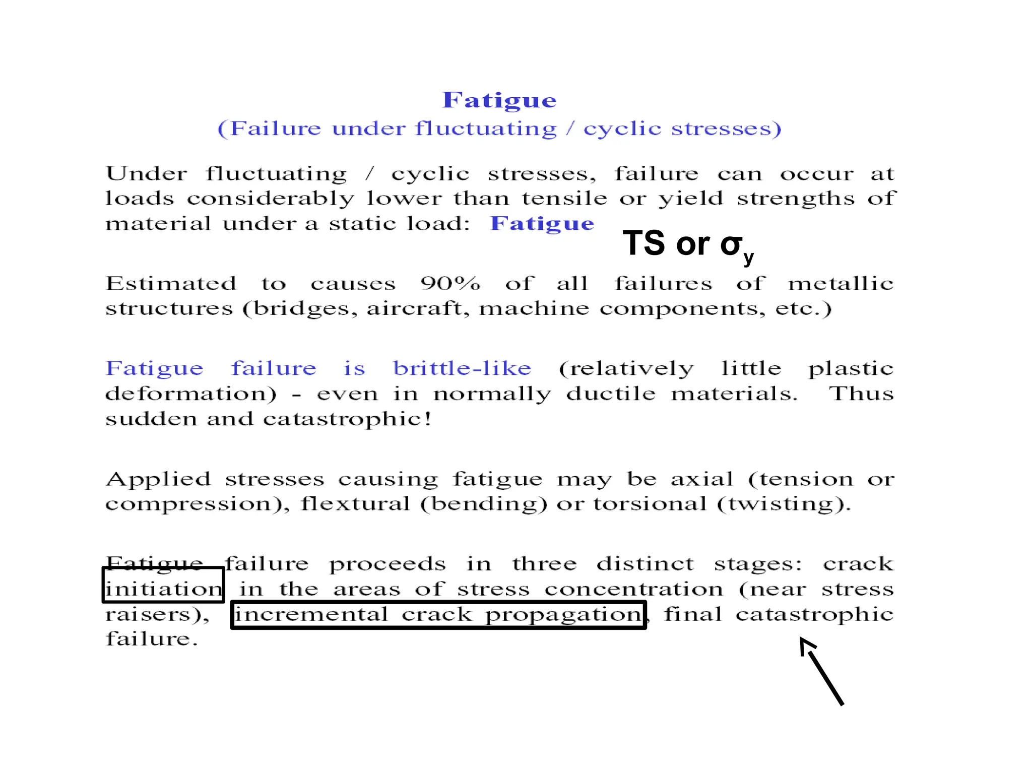
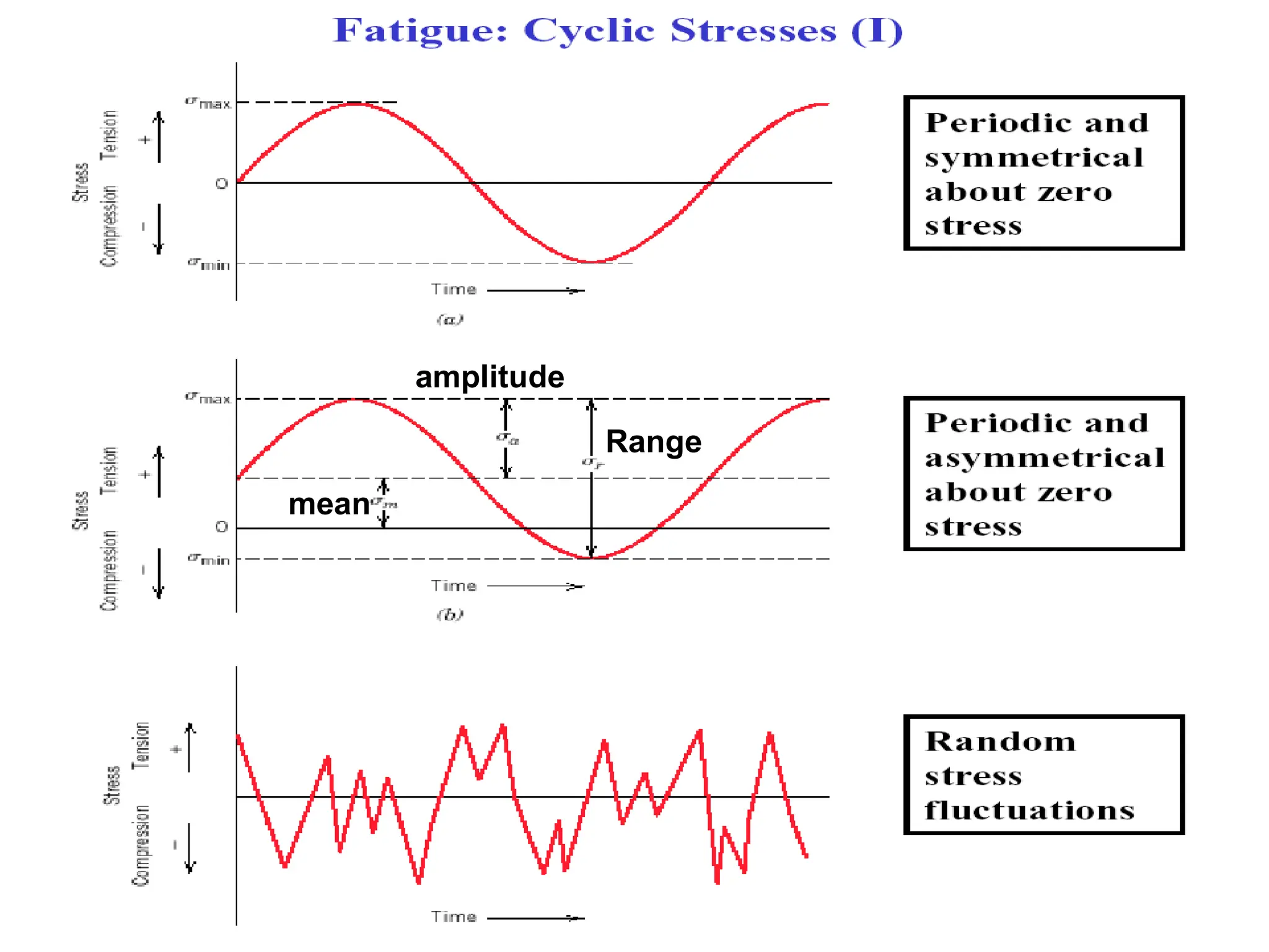
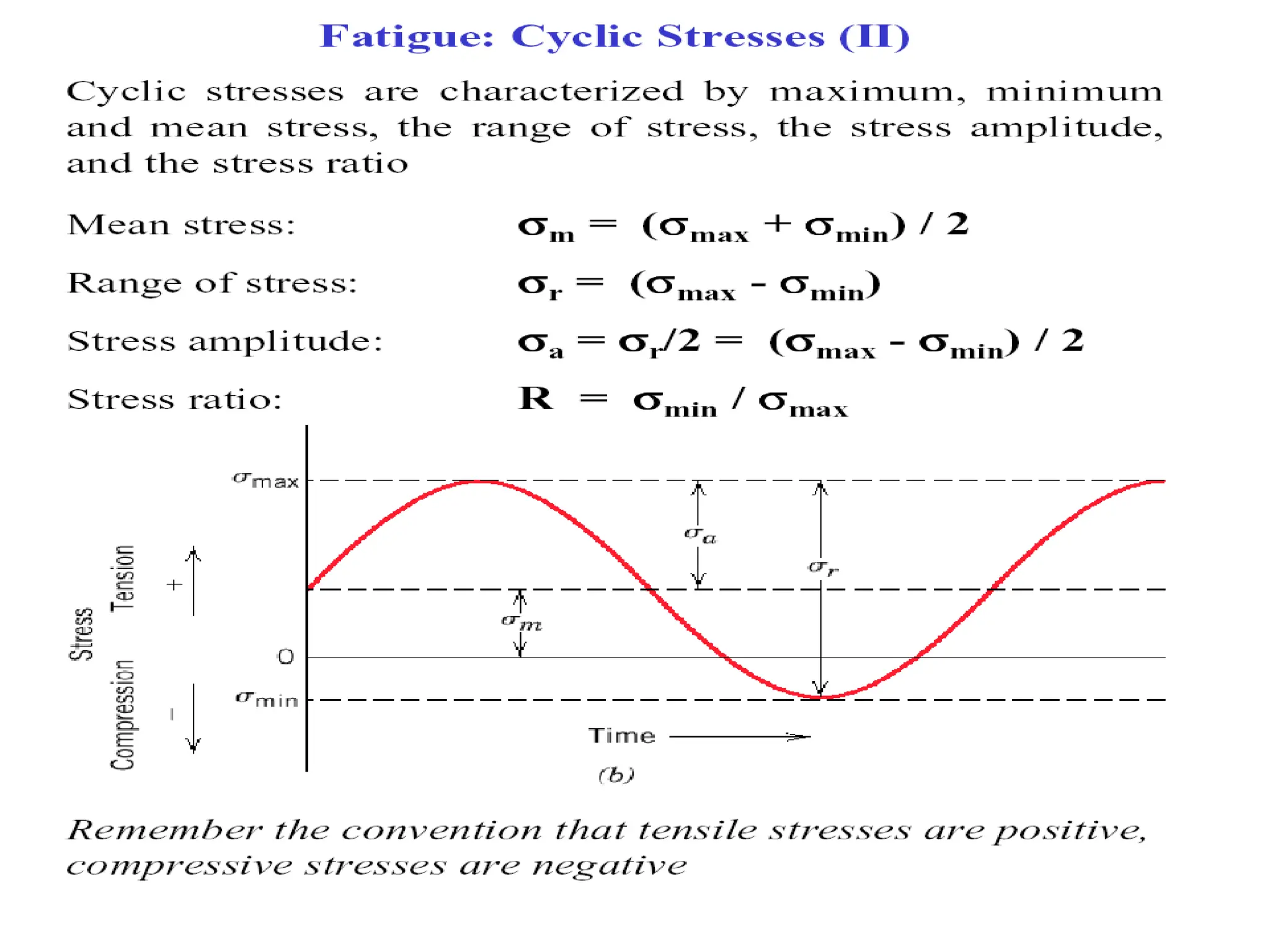
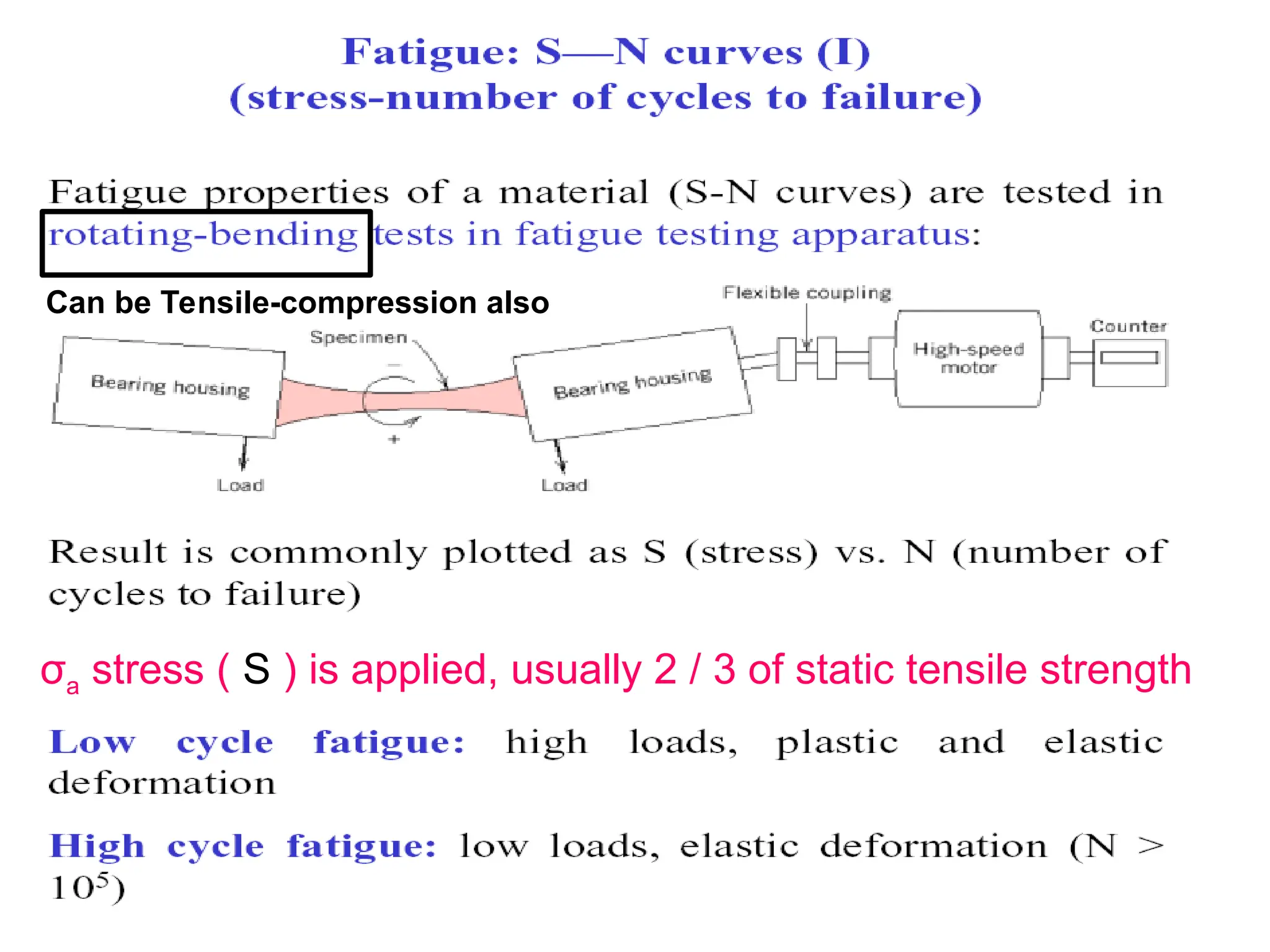
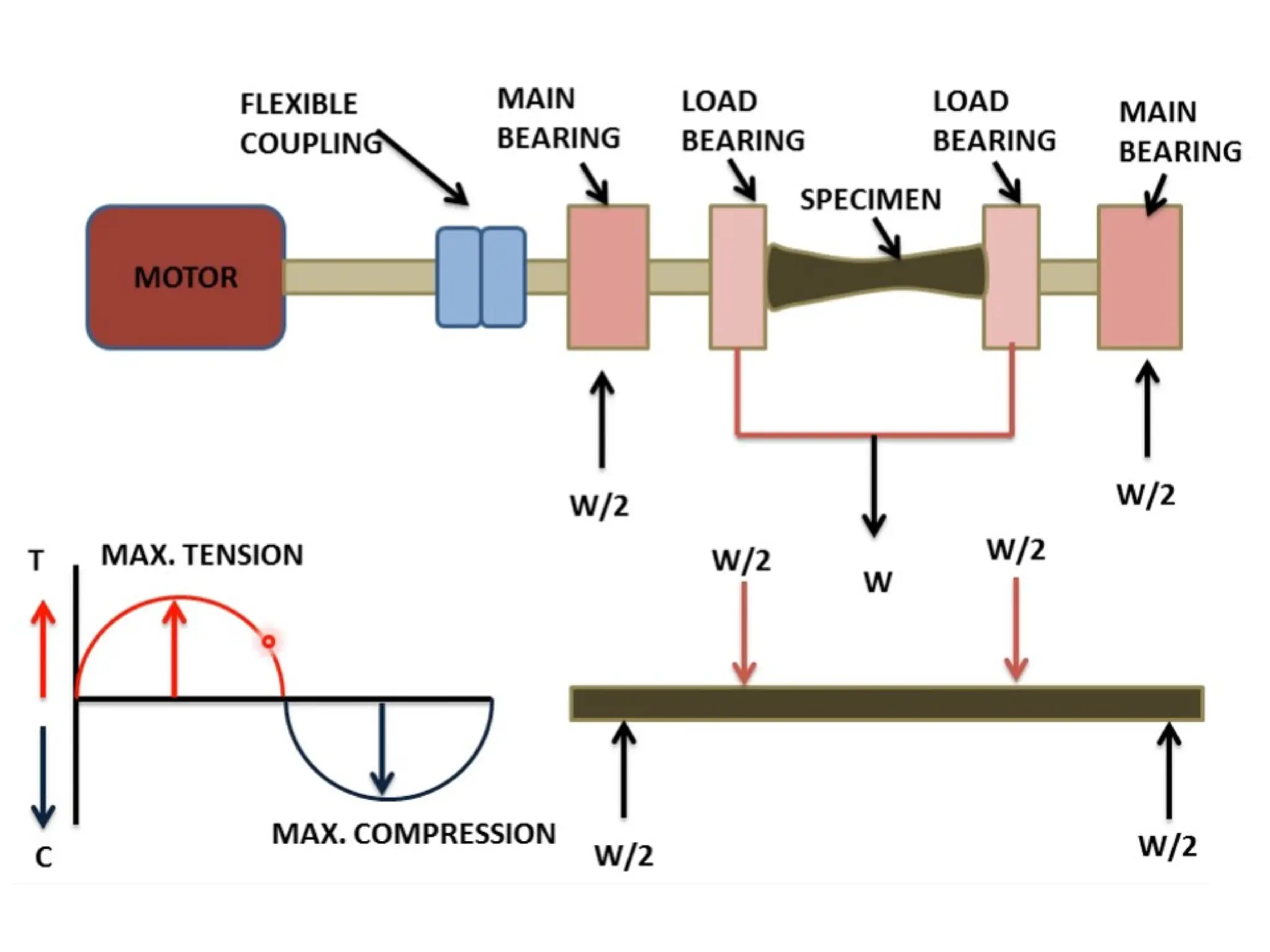
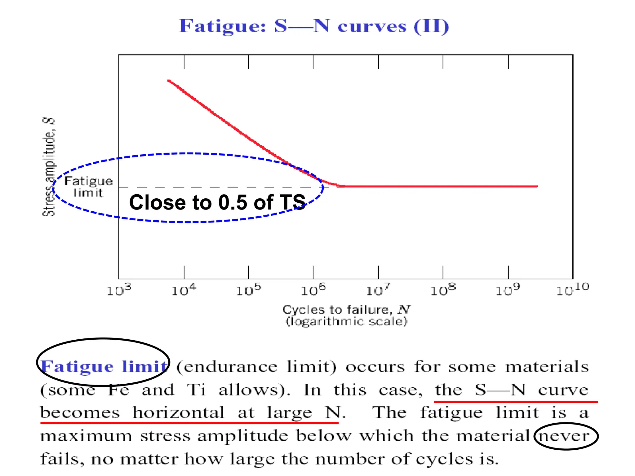
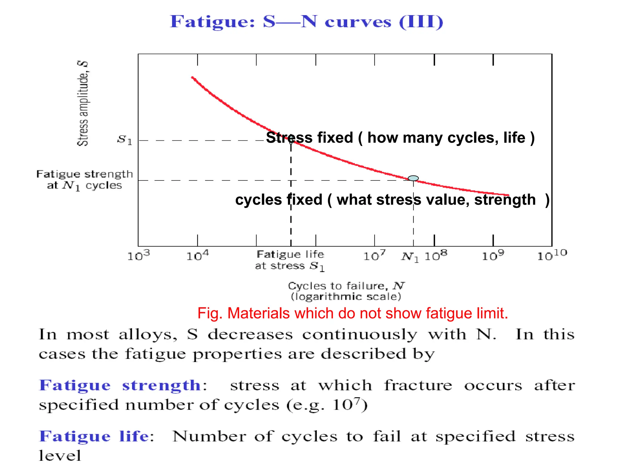
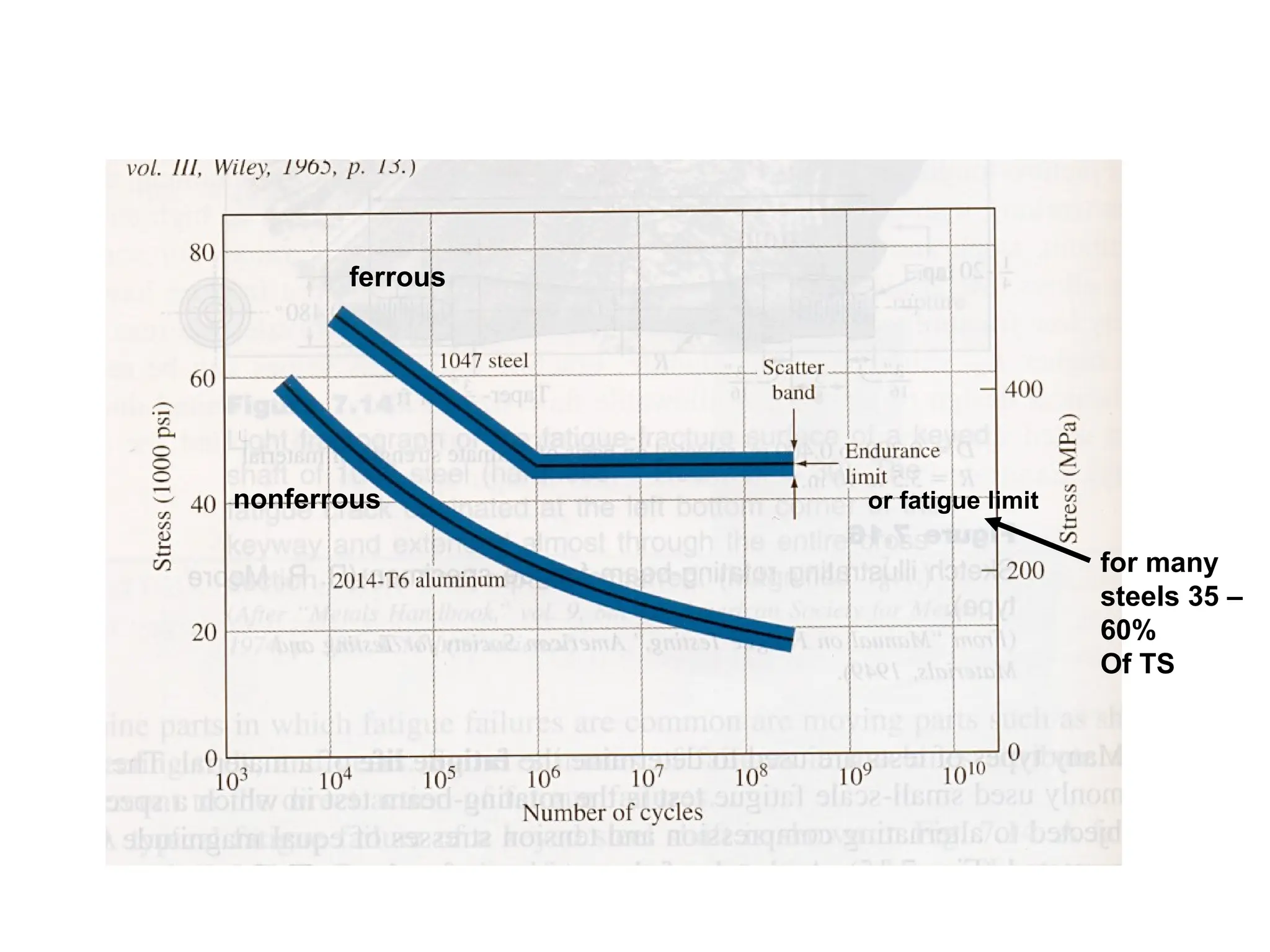
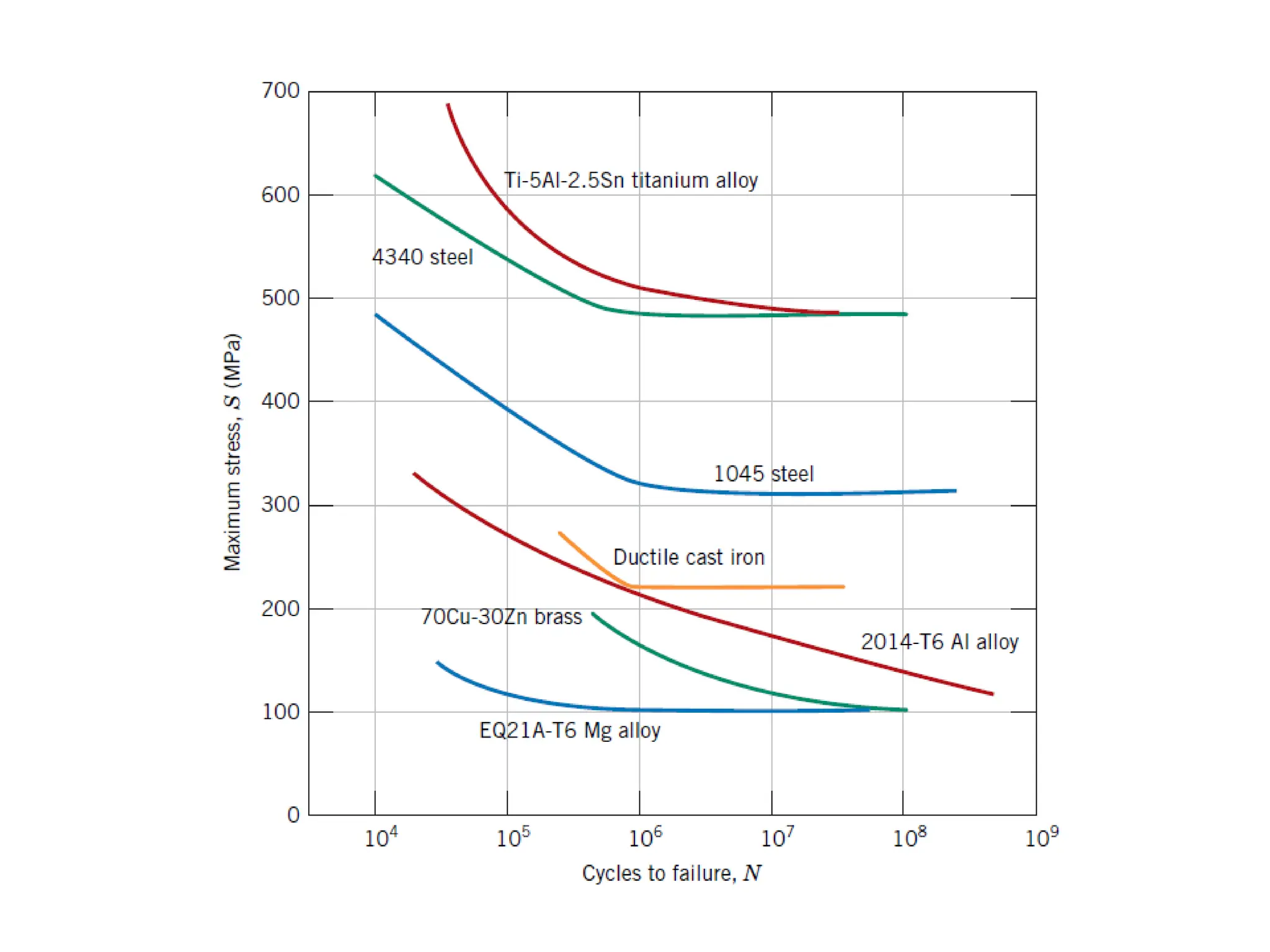
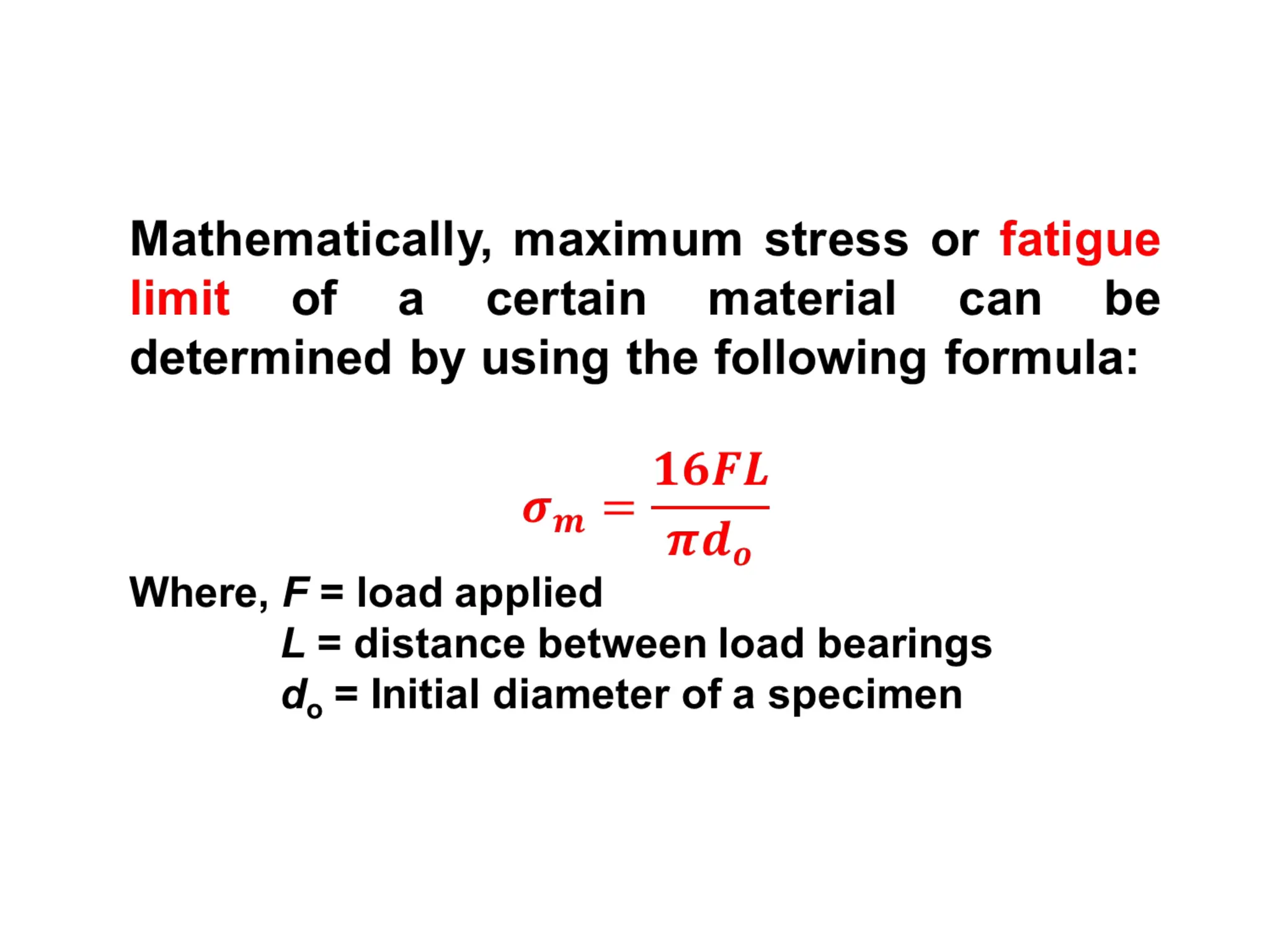
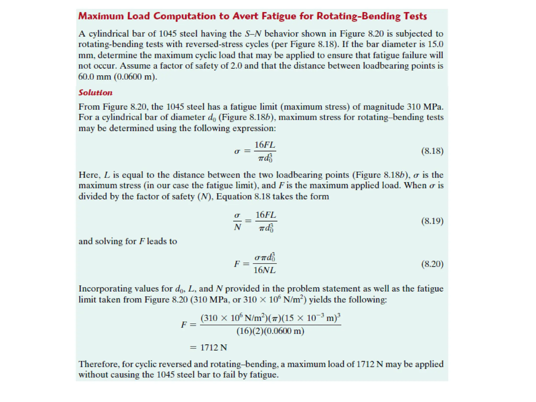
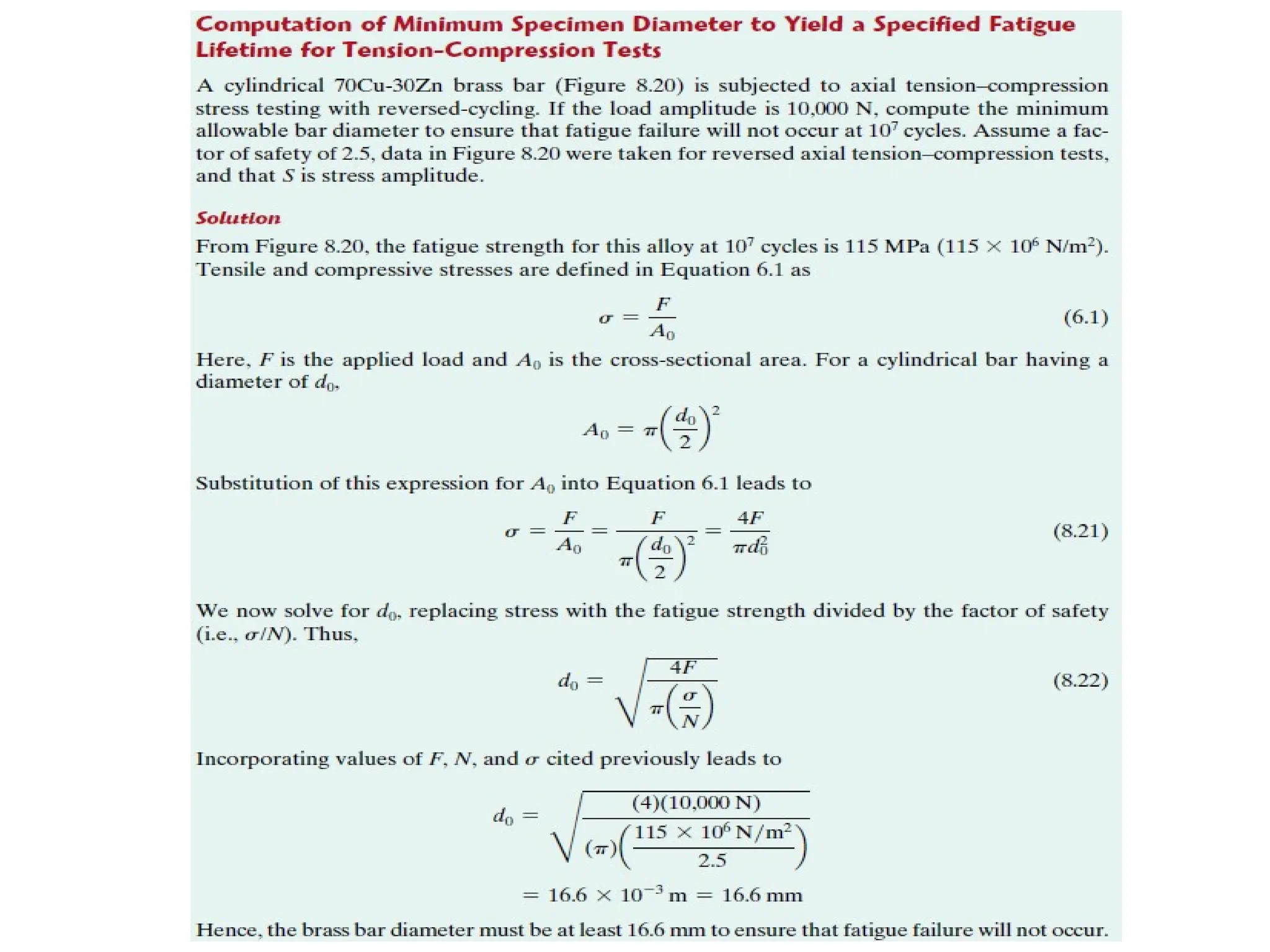
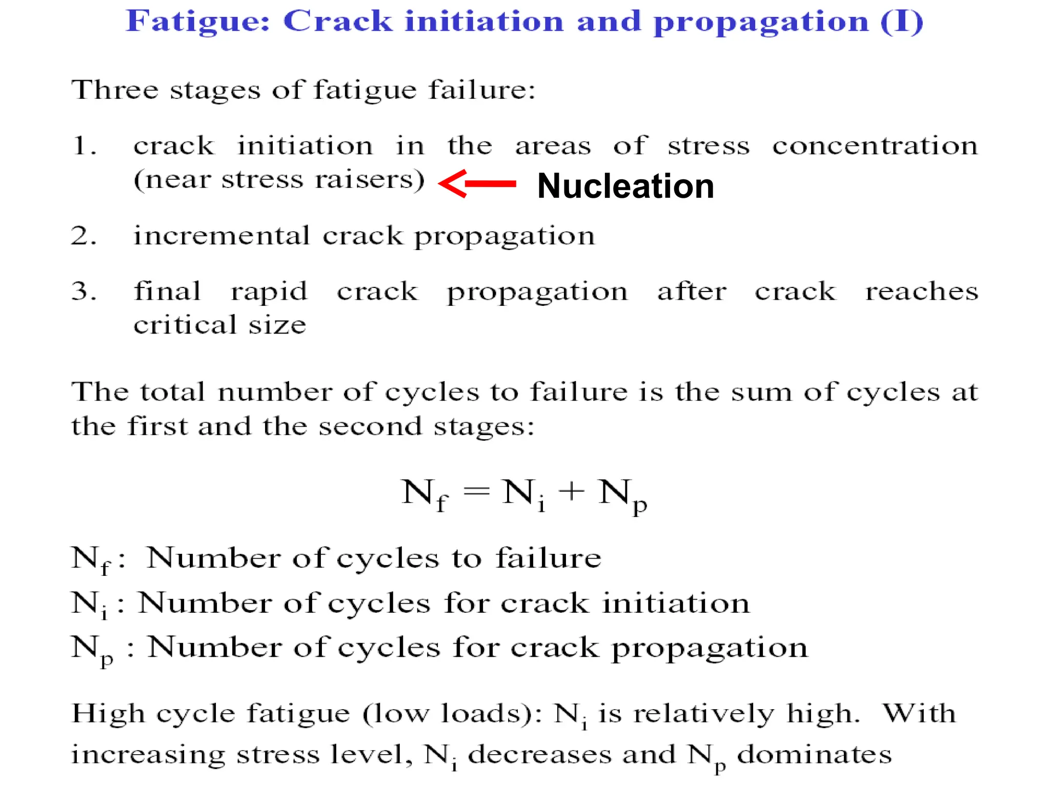
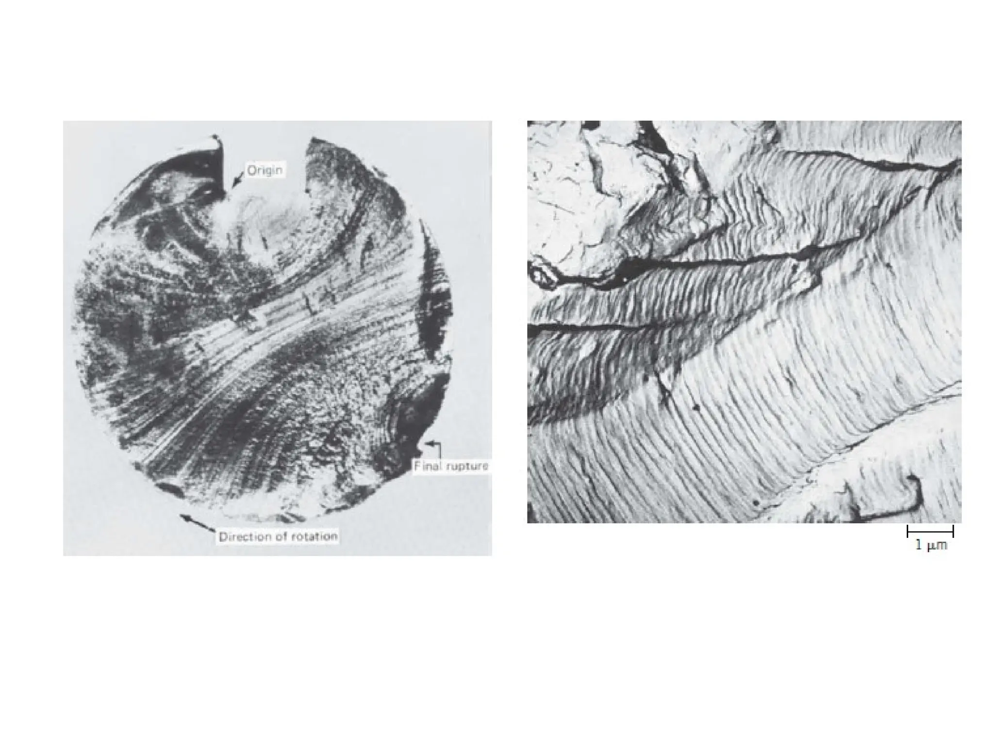
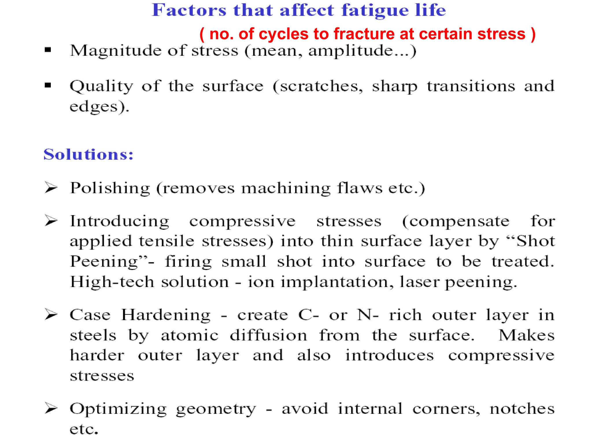
Fatigue
( fracture whenstress-strain fluctuates in time)
Stress may be Axial, Flexural or Torsional
1. occurs usually at lower applied stress
2. responsible for ~ 90 % damage
3. is brittle-like
4. called fatigue because each cycle incrementally adds
to the damage (to the strain, crack growth)
5. slow moving crack which rapidly picks up speed
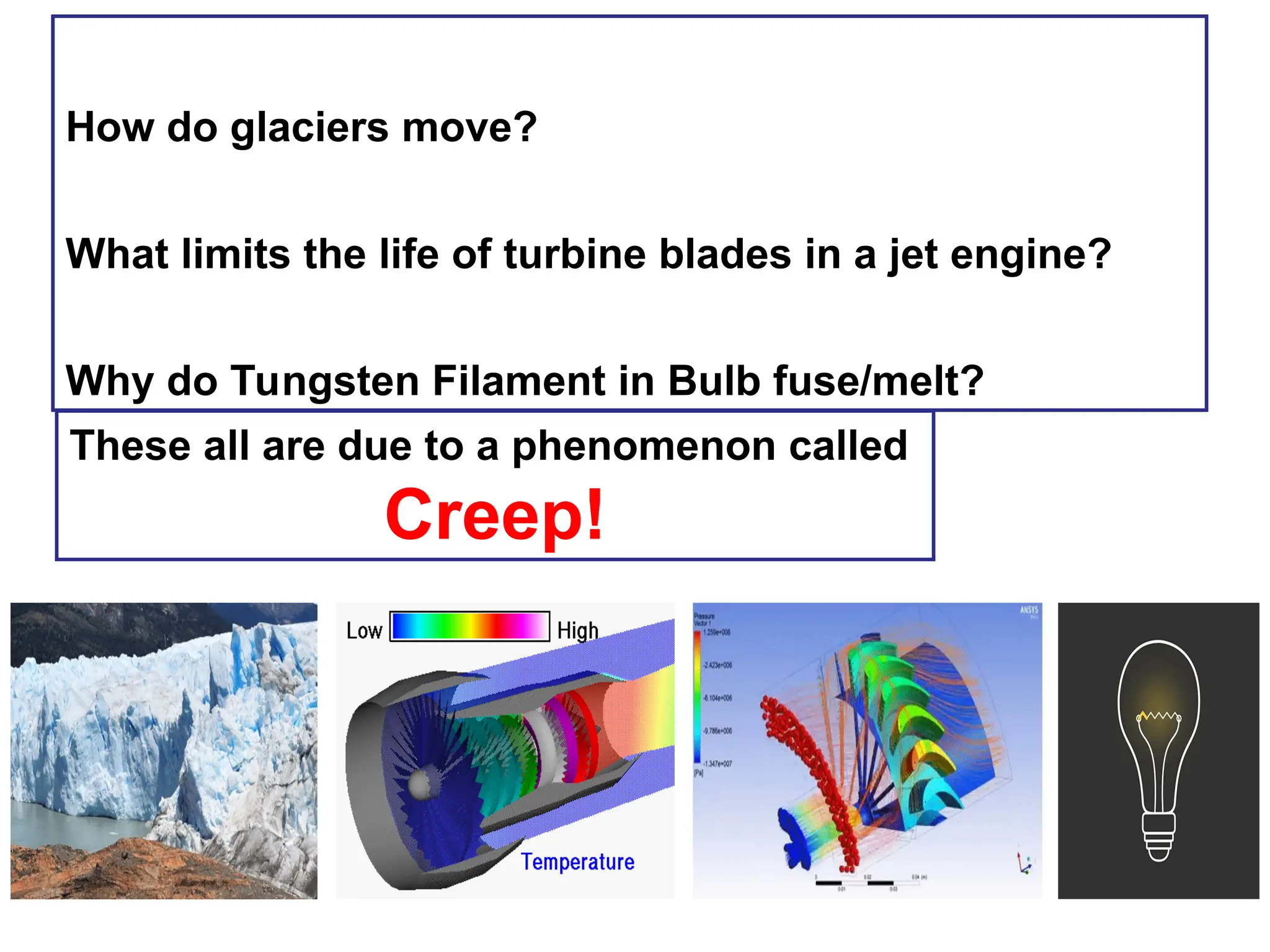
How do glaciersmove?
What limits the life of turbine blades in a jet engine?
Why do Tungsten Filament in Bulb fuse/melt?
These all are due to a phenomenon called
Creep!
61.
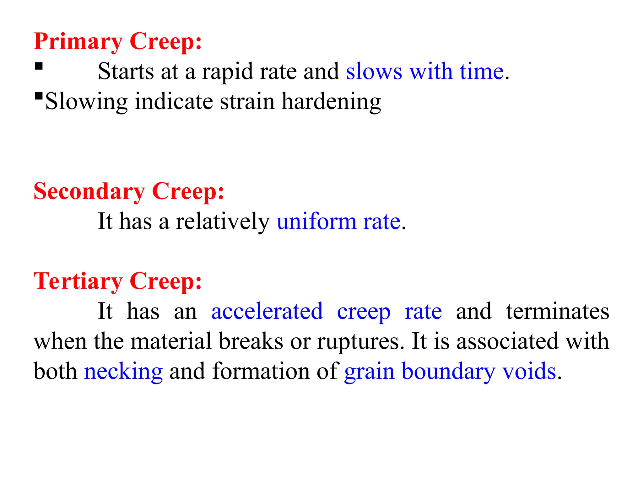
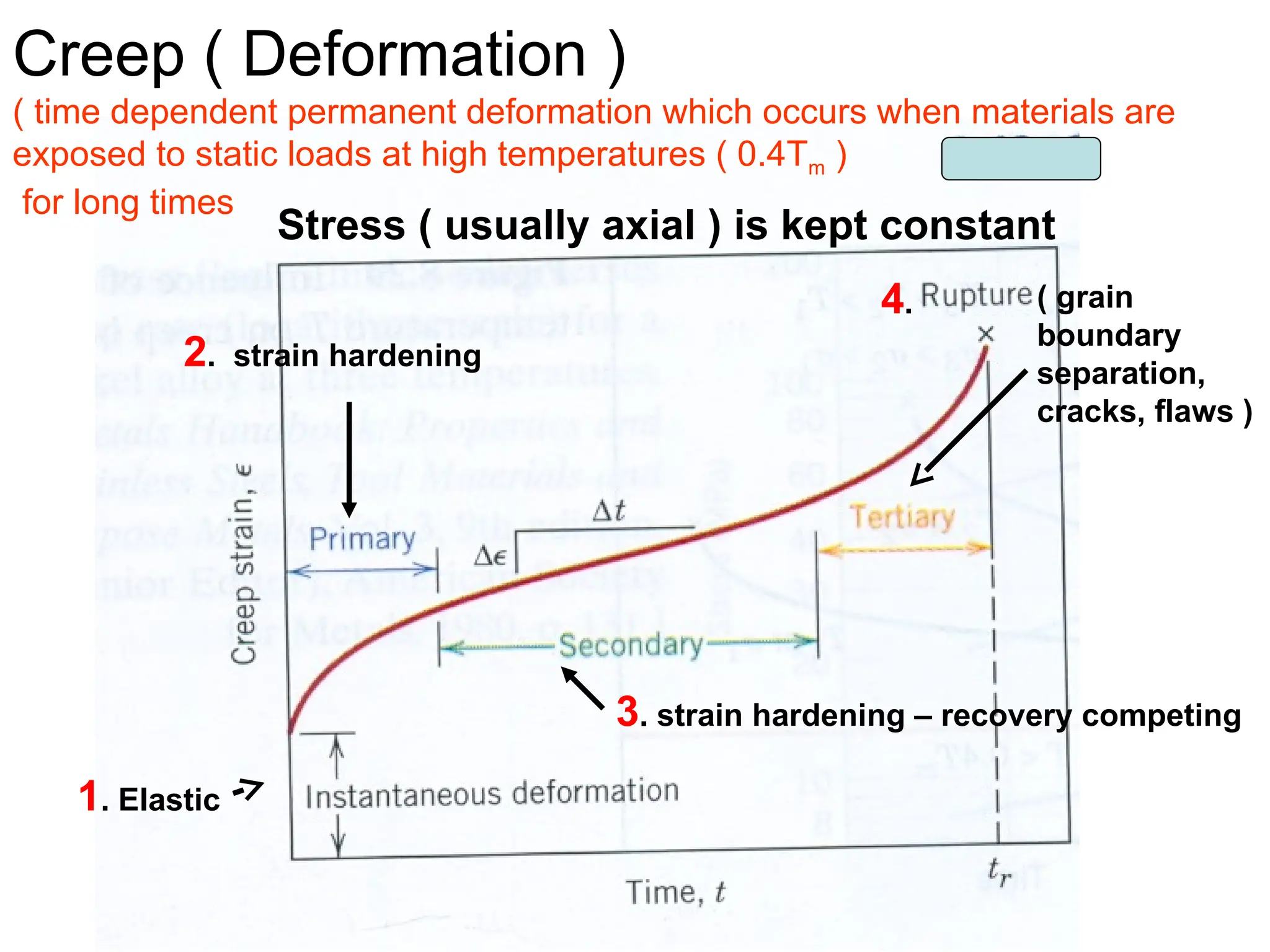
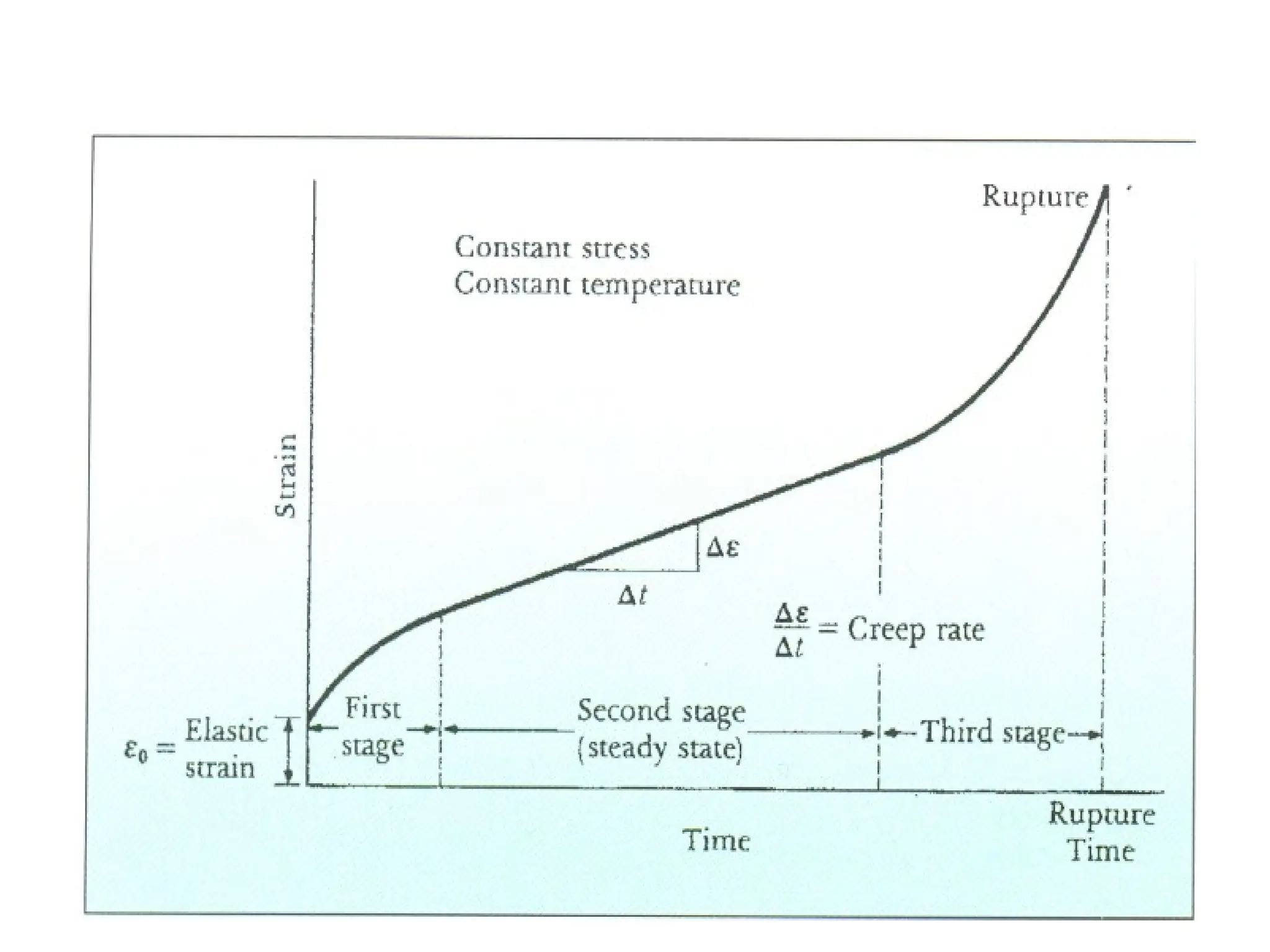
Primary Creep:
Startsat a rapid rate and slows with time.
Slowing indicate strain hardening
Secondary Creep:
It has a relatively uniform rate.
Tertiary Creep:
It has an accelerated creep rate and terminates
when the material breaks or ruptures. It is associated with
both necking and formation of grain boundary voids.
62.
Creep ( Deformation)
( time dependent permanent deformation which occurs when materials are
exposed to static loads at high temperatures ( 0.4Tm )
for long times
Stress ( usually axial ) is kept constant
2. strain hardening
3. strain hardening – recovery competing
( grain
boundary
separation,
cracks, flaws )
1. Elastic
4.
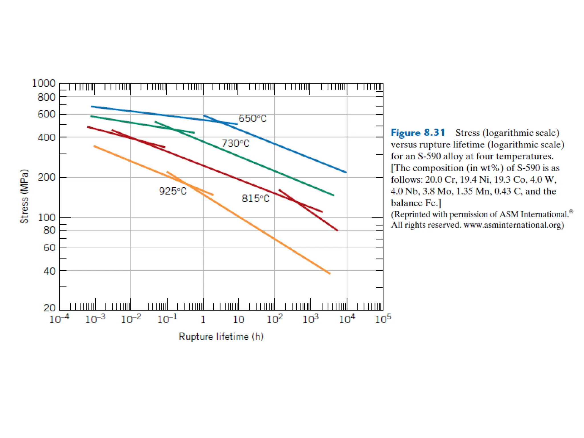
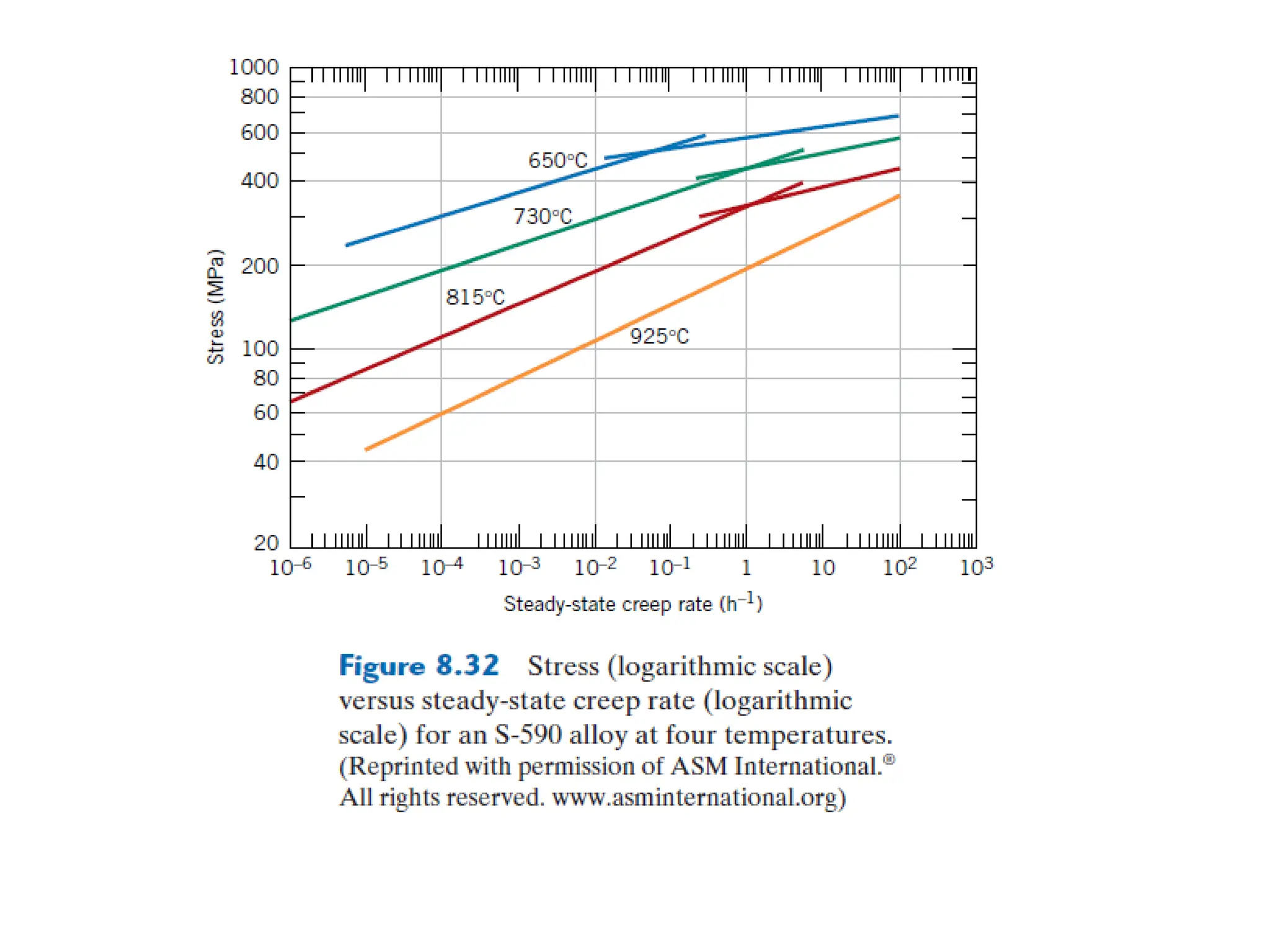
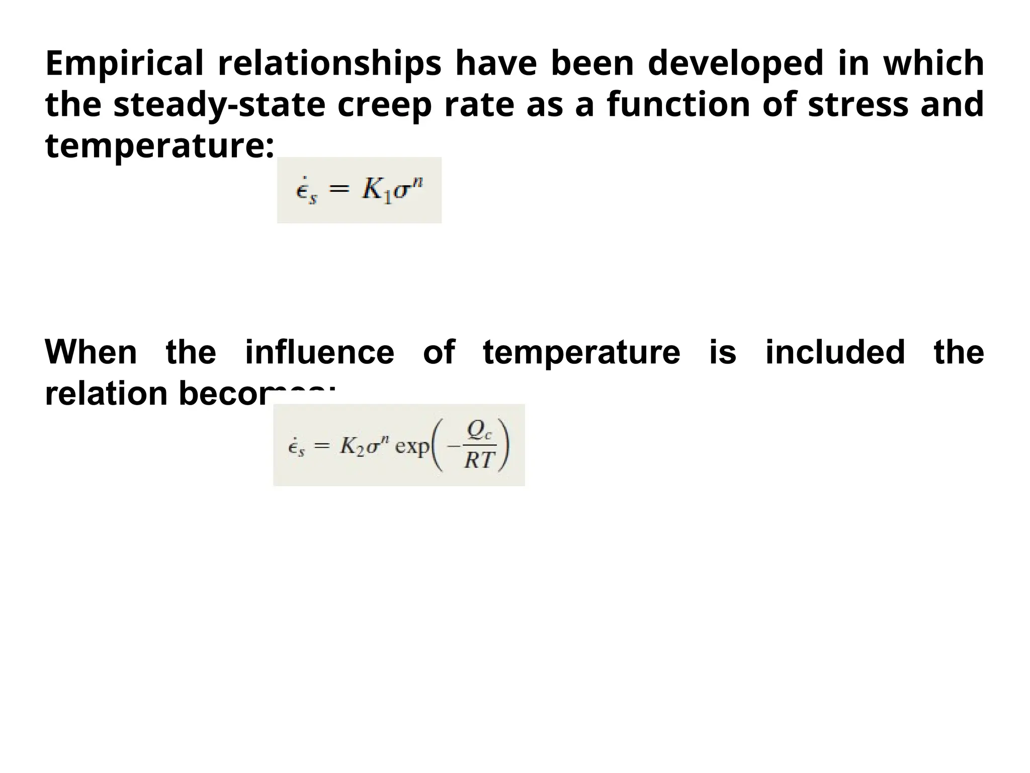
Empirical relationships havebeen developed in which
the steady-state creep rate as a function of stress and
temperature:
When the influence of temperature is included the
relation becomes:
70.
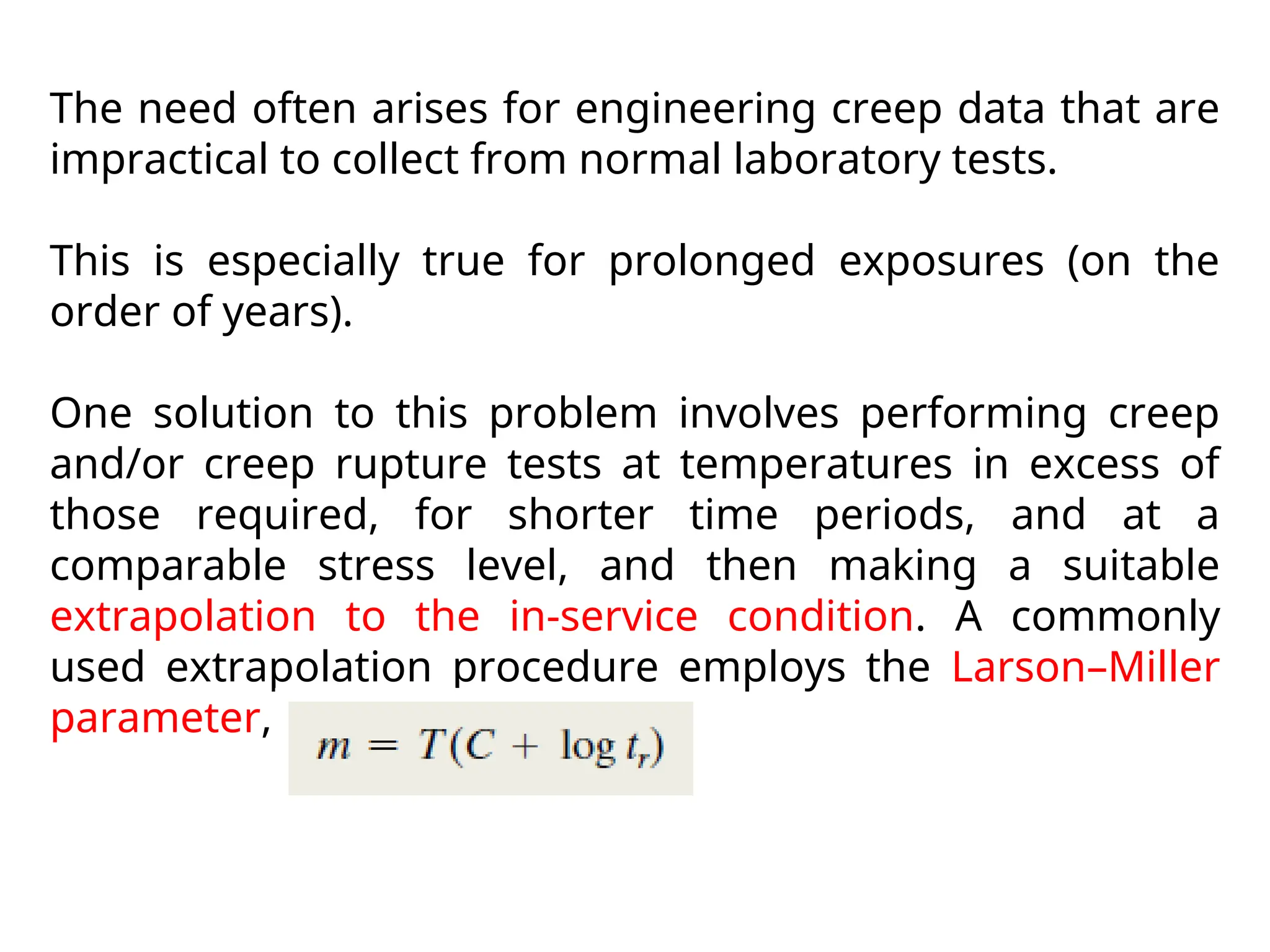
The need oftenarises for engineering creep data that are
impractical to collect from normal laboratory tests.
This is especially true for prolonged exposures (on the
order of years).
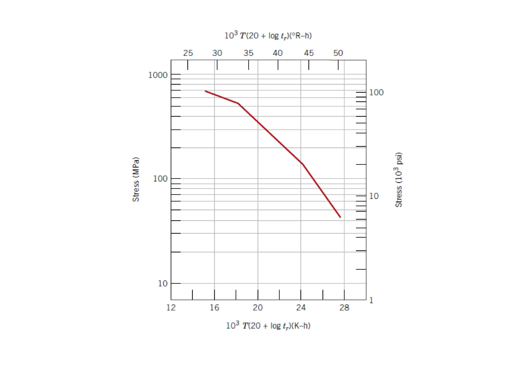
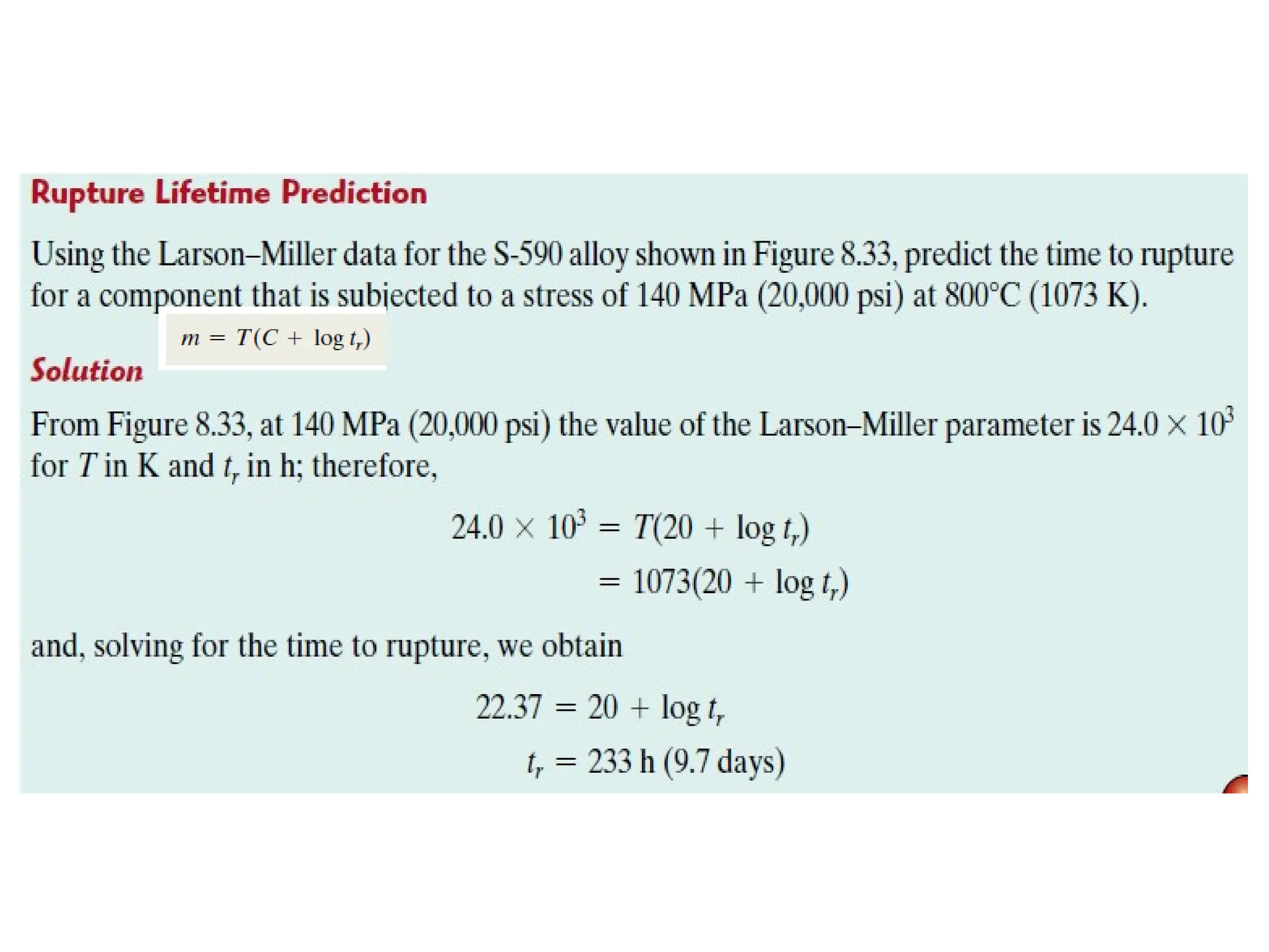
One solution to this problem involves performing creep
and/or creep rupture tests at temperatures in excess of
those required, for shorter time periods, and at a
comparable stress level, and then making a suitable
extrapolation to the in-service condition. A commonly
used extrapolation procedure employs the Larson–Miller
parameter, m, defined as:
73.
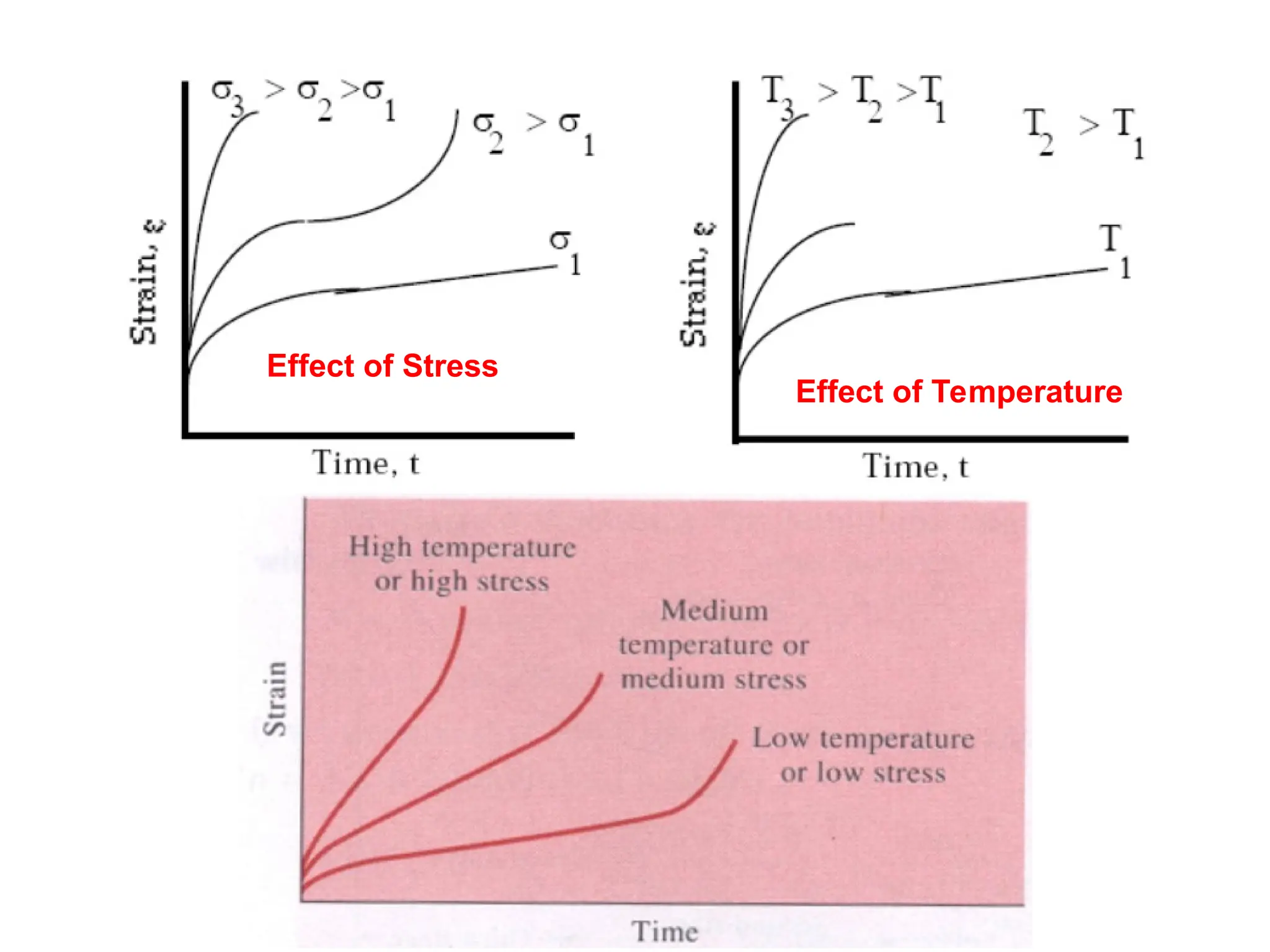
Factors Affecting Creep:
Temperature
Stress
MeltingPoint
Elastic Modulus
Grain Size
Greater the melting point, higher the elastic modulus and larger
the grain size of a material, the higher will be its creep life.
Stainless Steel and Super Alloys are especially resilient to creep.
Directional solidification and solid-solution alloying enhances the
creep life of a material.