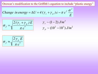
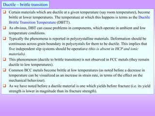
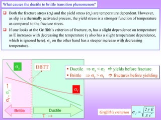
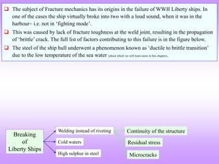
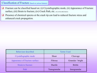
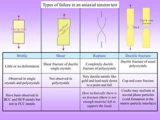
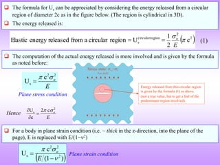
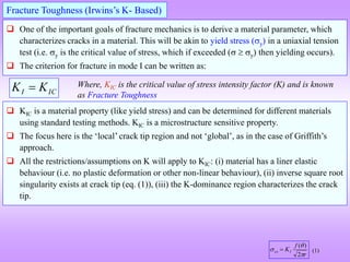
The document provides an overview of fracture mechanics, detailing the difference between brittle and ductile fractures as well as the significance of crack propagation in material failure. It highlights the theoretical strength of materials, the impact of crack geometry, and the factors influencing crack behavior under stress, while outlining the importance of characterizing fracture toughness. Historical context is given, linking concepts to the failures observed in WWII Liberty ships and early significant works in fracture theory.
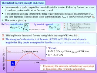
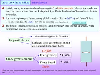
![ Fracture is related to propagation of cracks, leading to the failure of the
material/component.
If there are no pre-existing cracks, then a crack needs to nucleate before propagation (to
failure). Crack nucleation$ typically requires higher stress levels than crack propagation.
A crack is typically a ‘sharp*’ void in a material, which acts like a stress concentrator or
amplifier. Hence, crack is a amplifier of a ‘far field’mean stress. (Cracks themselves do not
produce stresses!). [A crack is a stress amplifier !].
Cracks in general may have several geometries. Even a circular hole can be considered as a
very ‘blunt’crack. A crack may lie fully enclosed by the material or may have ‘crack faces’
connected to the outer surface.
Crack propagation leads to the creation of new surface area, which further leads to the
increase in the surface energy of the solid. However, in fracture the surface energy involved
(the fracture surface energy) is typically greater than the intrinsic surface energy as fracture
involves ‘sub-surface’ atoms to some extent. Additionally, the fracture surface energy may
involve terms arising out of energy dissipation due to micro-cracking, phase transformation
and plastic deformation.
Fracture
2a
A crack in a material
Fracture surface energy (f) > Intrinsic surface energy ()
$ Regions of stress concentrations (arising from various sources) ‘help’ in the process.
* More about this sooner
Click here What is meant by failure?](https://image.slidesharecdn.com/7639952-221003160908-9b39cc93/85/7639952-ppt-3-320.jpg)
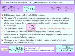
![2a
A crack in a material
What is a crack?
Funda Check
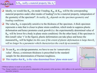
As we have seen crack is an amplifier of ‘far-field’ mean stress. The sharper the crack-tip,
the higher will be the stresses at the crack-tip. It is a region where atoms are ‘debonded’ and
an internal surface exists (this internal surface may be connected to the external surface).
Cracks can be sharp in brittle materials, while in ductile materials plastic deformation at the
crack-tip blunts the crack (leading to a lowered stress at the crack tip and further alteration
of nature of the stress distribution).
Even void or a through hole in the material can be considered a crack. Though often a crack is considered to
be a discontinuity in the material with a ‘sharp’ feature (i.e. the stress amplification factor is large).
A second phase (usually hard brittle phase) in a lens/needle like geometry can lead to stress
amplification and hence be considered a crack. Further, (in some cases) debonding at the
interface between the second phase and matrix can lead to the formation of an interface
crack.
As the crack propagates fresh (internal) surface area is created. The fracture surface energy
required for this comes from the strain energy stored in the material (which could further
come from externally applied loads). In ductile materials energy is also expended for plastic
deformation at the crack tip.
A crack reduces the stiffness of the structure (though this may often be ignored).
Hard second phase in
the material
Though often in figures the crack is shown to have a large lateral
extent, it is usually assumed that the crack does not lead to an
appreciable decrease in the load bearing area [i.e. crack is a local
stress amplifier, rather than a ‘global’ weakener by decreasing
the load bearing area].](https://image.slidesharecdn.com/7639952-221003160908-9b39cc93/85/7639952-ppt-6-320.jpg)
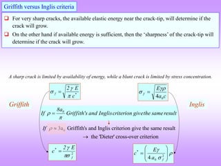
![‘Early Days’ of the Study of Fracture
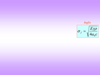
C.E. Inglis (seminal paper in 1913)[1]
A.A. Griffith (seminal paper in 1920)[2]
Stress based criterion for crack growth (local)
→ C.E. Inglis.
Energy based criterion for crack growth (global)
→ A.A. Griffith (Work done on glass very brittle material).
[1] C.E. Inglis, Stresses in a plate due to the presence of cracks and sharp corners, Trans. Inst. Naval Architechts 55 (1913) 219-230.
[2] A.A. Griffith, The phenomena of rupture and flow in solids, Philos. Trans. R. Soc. Lond. A221 (1920) 163-198. → Fat paper!](https://image.slidesharecdn.com/7639952-221003160908-9b39cc93/85/7639952-ppt-12-320.jpg)
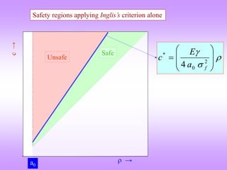
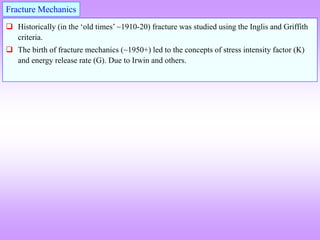
![Stress based criterion for crack propagation (Inglis criterion)
In 1913 Inglis observed that the stress concentration around a hole (or a ‘notch’) depended
on the radius of curvature of the notch. I.e. the far field stress (0) is amplified near the hole.
[(max / 0) is the stress concentration factor ()].
A ‘flattened’ (elliptical) hole can be thought of as a crack.
c
σ
σ 2
1
0
max
0 → applied “far field” stress
max → stress at hole/crack tip
→ hole/crack tip radius
c → length of the hole/crack
c
σ
σ 0
max 2
0
max
σ
A circular hole has a stress concentration factor of 3 [ = 3].
From Inglis’s formula it is seen that the ratio of crack length to crack tip radius is important
and not just the length of the crack.
hole crack
Sharper the crack, higher the stress concentration.
For sharp cracks
= c
For a circular hole
c
c
σ
σ 2
1
0
max
0
max 3σ
σ
One way of understanding this formula is that if max
exceeds t (the theoretical fracture stress), then the
material fails.
This is in spite of the fact that the applied stress is of
much lower magnitude than the theoretical fracture
stress.](https://image.slidesharecdn.com/7639952-221003160908-9b39cc93/85/7639952-ppt-14-320.jpg)
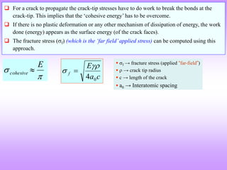
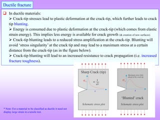
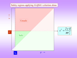
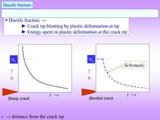
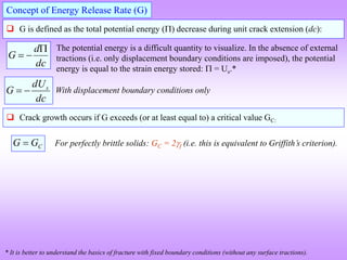
![Griffith’s criterion for brittle crack propagation
We have noted that the crack length does not appear ‘independently’ (of the crack tip radius)
in Inglis’s formula. Intuitively we can feel that longer crack must be more deleterious.
Another point noteworthy in Inglis’s approach is the implicit assumption that sufficient
energy is available in the elastic body to do work to propagate the crack. (‘What if there is
insufficient energy?’) (‘What if there is no crack in the body?’). Also, intuitively we can
understand that the energy (which is the elastic energy stored in the body) should be
available in the proximity of the crack tip (i.e. energy available far away from the crack tip
is of no use!).
Keeping some of these factors in view, Griffith proposed conditions for crack propagation:
(i) bonds at the crack tip must be stressed to the point of failure (as in Inglis’s criterion),
(ii) the amount of strain energy released (by the ‘slight’ unloading of the body due to crack
extension) must be greater than or equal to the surface energy of the crack faces created.
The second condition can be written as:
dc
dU
dc
dUs
Us → strain energy
U → surface energy
(Energy per unit area: [J/m2])
dc → (‘infinitesimal’) increase in the
length of the crack (‘c’ is the crack length)
We look at the formulae for Us and U next.
Essentially this is like energy balance (with the ‘=‘ sign) → the surface energy for the extended
crack faces comes from the elastically stored energy (in the fixed displacement case)](https://image.slidesharecdn.com/7639952-221003160908-9b39cc93/85/7639952-ppt-16-320.jpg)
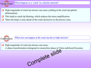
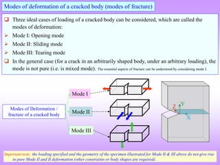
![ The strain energy released on the introduction of a very narrow elliptical double ended
crack of length ‘2c’ in a infinite plate of unit width (depth), under an uniform stress a is
given by the formula as below.
E
U
U
U a
crack
with
crack
without
2
2
s
c
U
energy
elastic
in
Reduction
This is because the body with the crack has a lower elastic
energy stored in it as compared to the body without the crack
(additionally, the body with the crack is less stiffer). Also, the
assumption is that the introduction of a crack does not alter
the far-field stresses (or the load bearing area significantly).
Notes:
The units of Us is [J/m] (Joules per meter depth of the crack→ as
this is a through crack).
Though Us has a symbol of energy, it is actually a difference
between two energies
(i.e. two states of a body→ one with a crack and one without).
Half crack length ‘c’ appears in the formula.
E is assumed constant in the process (the apparent modulus will decrease
slightly).
a is the ‘far field’ stress (this may result from displacements
rather than from applied forces see note later).
Should be written with a ve
sign if U = (Ufinal Uinitial)
For now we assume that these stresses
arise out of ‘applied’ displacements](https://image.slidesharecdn.com/7639952-221003160908-9b39cc93/85/7639952-ppt-17-320.jpg)
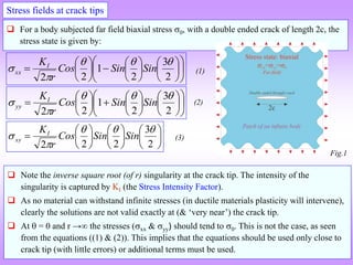
![ The surface energy of the crack of length 2c & unit width/depth is:
c
γ
U f
4
energy
surface
Fracture
This is the difference in the energy between a body with a crack and one without a crack.
As pointed out before, the surface energy is the fracture surface energy and not just the
surface free energy. The origin of this energy is contributions from dissipative mechanisms
like plastic deformation, micro-cracking & phase transformation, in addition to the energy
of the ‘broken bonds’.
The units are Joules per meter depth of the body: [J/m].
[J/m]
Important note
The “Griffith experiment” is easily understood in displacement control mode (i.e. apply a
constant displacement and ‘see’ what happens to the crack) and is more difficult to
comprehend in the force control mode (by applying constant ‘far-field’ forces).
In force control mode, the forces do work on the system and hence the ‘energy accounting’
process is more involved.
Hence, it is better to visualize as arising from a ‘far field’ applied displacements.
c
f
2
c
U
](https://image.slidesharecdn.com/7639952-221003160908-9b39cc93/85/7639952-ppt-19-320.jpg)
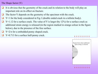
![
E
a
f
2
2
c
c
4
U
crack
a
of
on
introducti
the
on
energy
in
Change
c →
U
→
0
*
c
dc
U
d
*
c
0
c
0
0
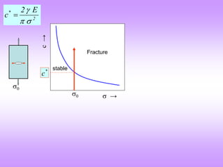
An alternate way of understanding the Griffith’s criterion (energy based)
c
γ
U f
4
E
a
2
2
s
c
U
This change in energy (U) should be negative with an increase in crack
length (or at worst equal to zero). I.e. (dU/dc) ≤ 0.
At c* the slope of U vs c curve is zero [(dU/dc)c* = 0]. This is a point
of unstable equilibrium.
With increasing stress the value of c* decreases (as expected→ more
elastic strain energy stored in the material).
Stable
cracks Unstable cracks
For ready reference
Negative slope
Positive slope
c →
U
→
*
1
c *
2
c](https://image.slidesharecdn.com/7639952-221003160908-9b39cc93/85/7639952-ppt-21-320.jpg)

![‘Modern’ Fracture Mechanics
G.R. Irwin[1]
Stress Intensity Factor (K)
Material Parameter Fracture Toughness (KC)
Energy Release Rate (G)
Material Parameter Critical Energy Release Rate (GC)
J-integral
[1] G.R. Irwin, “Fracture Dynamics”, in: “Fracture of Metals”, ASM, Cleaveland, OH, 1948, pp.147-166.
[2] G.R. Irwin, “Analysis of stresses and strains near the end of a crack traversing a plate, J. Appl. Mech 24 (1957) 361-364.](https://image.slidesharecdn.com/7639952-221003160908-9b39cc93/85/7639952-ppt-24-320.jpg)

![Understanding the stress field equation
2
3
2
1
2
2
Sin
Sin
Cos
r
KI
xx
r
f
KI
xx
2
)
(
→
c
Y
KI
0
‘Shape factor’ related to ‘Geometry’
Indicates mode I ‘loading’
Half the crack length
“KI (the Stress Intensity Factor) quantifies the magnitude of the effect of stress singularity at
the crack tip”[1].
Quadrupling the crack length is equivalent to doubling the stress ‘applied’. Hence, K
captures the combined effect of crack length and loading. The remaining part in equation(1)
is purely the location of a point in (r, ) coordinates (where the stress has to be computed).
Note that there is no crack tip radius () in the equation! The assumptions used in the
derivation of equations (1-3) are: = 0, infinite body, biaxial loading.
‘Y’ is considered in the next page.
[1] Anthony C. Fischer-Cripps, “Introduction to Contact Mechanics”, Springer, 2007.
(1)](https://image.slidesharecdn.com/7639952-221003160908-9b39cc93/85/7639952-ppt-30-320.jpg)
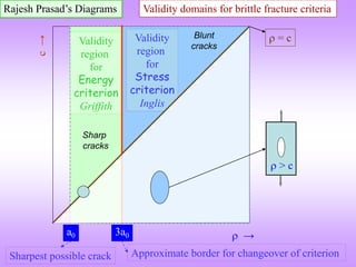
![Summary of Fracture Criteria
Criterion named after &
[important quantities]
Comments Fracture occurs if Relevant formulae
Inglis Involves crack tip radius
Griffith Involves crack length
Irwin [K] Concept of stress intensity factor.
KI > KIC
(in mode I)
- [G]
Energy release rate based. Same as K based
criterion for elastic bodies.](https://image.slidesharecdn.com/7639952-221003160908-9b39cc93/85/7639952-ppt-32-320.jpg)
![Material KIC [MPam]**
Cast Iron 33
Low carbon steel 77
Stainless steel 220
Al alloy 2024-T3 33
Al alloy 7075-T6 28
Ti-6Al-4V 55
Inconel 600 (Ni based alloy) 110
* We have already noted that fracture toughness is a microstructure sensitive property and hence to get ‘true’value the
microstructure has to be specified.
** Note the strange units for fracture toughness!
[1] Fracture Mechanics, C.T. Sun & Z.-H. Jin, Academic Press, Oxford (2012).
Fracture Toughness* (KIC) for some typical materials [1]](https://image.slidesharecdn.com/7639952-221003160908-9b39cc93/85/7639952-ppt-35-320.jpg)