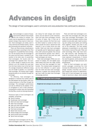
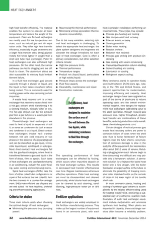
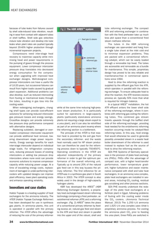
HEAT EXCHANGERS
Fertilizer International  463 | November - December 2014	 www.fertilizerinternational.com 33
tube sheet
Straight-tube heat exchanger (one pass tube-side)
tube sheet
shell-side fluid in
tube-side fluid out
shell-side fluid out
tube-side fluid in
shellbaffles
inletplenum
outletplenum
tube bundle with straight tubes
Fig 1: A shell and tube heat exchanger
A
heat exchanger is a piece of equip-
ment built for efficient heat transfer
from one medium to another. The
media may be separated by a solid wall to
prevent mixing or they may be in direct con-
tact. Heat exchangers are widely used in
many chemical and fertilizer plants, natural
gas processing and petroleum refineries.
There are three primary classifications
of heat exchangers according to their flow
arrangement. In parallel-flow heat exchang-
ers, the two liquids enter the exchanger at
the same end and travel in parallel to one
another to the other side. In counter-flow
heat exchangers, the liquids enter the
exchanger from opposite ends. The coun-
ter- current design is viewed as the most
efficient, as it can transfer the most heat
from the heat medium due to the fact that
the average temperature difference along
any unit length is greater. In a cross-flow
heat exchanger, the liquids travel roughly
perpendicularly to one another through the
exchanger.
For efficiency, heat exchangers are
designed to maximise the surface area of
the wall between the two liquids, while mini-
mising resistance to fluid flow through the
exchanger. The exchanger’s performance
can also be affected by the addition of fins
or corrugations in one or both directions,
increasing the surface area and channelling
the fluid flow, as well as inducing turbulence.
Numerous types of heat exchangers are
available, comprising:
l	 Electric heating
l	 Double-pipe heat exchanger
l	 Shell and tube heat exchanger
l	 Plate heat exchanger
l	 Plate and shell heat exchanger
l	 Plate fin heat exchanger
l	 Fluid heat exchanger
l	 Waste heat recovery units
l	 Phase-change heat exchanger
l	 Direct-contact heat exchanger
l	 Spiral heat exchanger.
Double-pipe heat exchangers are the sim-
plest exchangers used in industries. They
are cheap for both design and mainte-
nance and are ideal for small industries.
Shell and tube heat exchangers consist
of series of tubes. (Fig. 1) One set of
these tubes contains the fluid that must
be either heated or cooled so that it can
either provide the heat or absorb the heat
required. A set of tubes forms the tube
bundle. Shell and tube heat exchangers
are typically used for high-pressure applica-
tions (with pressures greater than 30 bar
and temperatures greater than 260°C).
Their shape ensures that shell and tube
heat exchangers are robust.
Plate heat exchangers (PHEs) are com-
posed of multiple, thin and slightly sepa-
rated plates that have very large surface
areas and fluid flow passages for heat
transfer. This stacked plate arrangement
can be more effective in a given space
than the shell and tube heat exchanger.
Advances in gasket and brazing technol-
ogy have made the plate heat exchanger
increasingly practical.
Plate and shell heat exchangers com-
bine plate heat exchanger with shell and
tube heat exchanger technologies. The
heart of the heat exchanger contains a fully
welded circular plate pack made by press-
ing and cutting round plates and welding
them together. Nozzles carry flow in and
out of the plate-pack. The fully welded
plate-pack is assembled in an outer shell
that creates a second flow path. Plate and
shell technology offers high heat trans-
fer, high pressure, high operating tem-
peratures, compact size, low fouling and
close approach temperatures. It avoids
the need for gaskets, which provides secu-
rity against leakage at high pressures and
temperatures.
Plate fin heat exchangers use sand-
wiched passages containing fins that
increase the effectiveness of the unit. The
design includes cross-flow and counter-
flow coupled with various fin applications.
Plate and fin heat exchangers are usually
made of aluminium alloys, which provide
Advances in design
The design of heat exchangers used in ammonia and urea production has continued to advance.
HEAT EXCHANGERS
33	 www.fertilizerinternational.com Fertilizer International  463 | November - December 2014
“For efficiency, heat
exchangers are
designed to maximise
the surface area of
the wall between the
two liquids, while
minimising resistance
to fluid flow through
the exchanger.
high heat transfer efficiency. The material
enables the system to operate at lower
temperature and reduce the weight of the
equipment. Plate and fin heat exchangers
are mostly used for low temperature ser-
vices, such as natural gas and air sepa-
ration units. They offer high heat transfer
efficiency, especially in gas treatment and
a larger heat transfer area, being approxi-
mately five times lighter in weight than a
shell and tube heat exchanger. Plate fin
heat exchangers can also withstand high
pressures. On the other hand, the narrow
pathways can led to clogging and are dif-
ficult to clean. The aluminium alloys are
also susceptible to mercury liquid embat-
tlement failure.
In a fluid heat exchanger, gas passes
upwards through a shower of liquid, and
the liquid is then taken elsewhere before
being cooled. This is commonly used for
cooling gases while also removing certain
impurities.
A waste heat recovery unit is a heat
exchanger that recovers excess heat from
a hot gas stream while transferring it to
a working medium, typically water or oils.
The hot gas stream can be the exhaust
gas from a gas turbine or a waste gas from
elsewhere in the process.
Phased-change heat exchangers are
used to heat a liquid to evaporate or boil
it, or serve as condensers to cool a vapour
and condense it to a liquid. Direct-contact
heat exchangers involve heat transfer
between hot and cold streams of two
phases in the absence of a separating wall
and can be classified as gas-liquid, immis-
cible liquid-liquid, solid-liquid or solid-gas.
Most direct-contact heat exchangers fall
into the gas-liquid category, where heat is
transferred between a gas and liquid in the
form of drops, films or sprays. Such types
of heat exchangers are used predominantly
in air conditioning, industry hot water heat-
ing, water cooling and condensing plants.
Spiral heat exchangers (SHEs) take the
form of either coiled tube configurations or
a pair of flat surfaces that are coiled to form
the two channels in a counter-flow arrange-
ment. SHEs make efficient use of space and
are well suited for heat recovery, pre-heat-
ing and effluent cooling applications.
Criteria for choice
Three main criteria apply when choosing
the optimal design of heat exchangers:
l	 Minimising the pressure drop (pumping
power)
l	 Maximising the thermal performance
l	 Minimising entropy generation (thermo-
dynamic irreversibility).
Due to the many variables, selecting opti-
mal heat exchangers is challenging. To
select the appropriate heat exchanger, the
plant system designers and engineers will
consider the design limitations for each
type of heat exchanger. Cost is often a
primary consideration, but other selection
criteria include:
l	 High/low pressure limits
l	 Thermal performance
l	 Temperature ranges
l	 Product mix (liquid/liquid, particulates
or high solids/liquid)
l	 Pressure drops across the exchanger
l	 Fluid flow capacity
l	 Cleanability, maintenance and repair
l	 Construction materials.
heat exchanger installation performing an
important role. These roles may include:
l	 Process gas heating and cooling
l	 Gas compression heat recovery
l	 Process waste recovery
l	 Steam generation
l	 Boiler water heating
l	 Reactor preheat
l	 Reaction heat recovery
l	 Process gas chilling with product con-
densing
l	 Gas cooling with steam condensing
l	 Vapour-liquid separation column reboiling
l	 Solvent heating and cooling
l	 Lubrication oil cooling
l	 Refrigerant vapour cooling.
Many ammonia plants in operation today
were built between 25-35 years ago, nota-
bly in the FSU and United States, and
present opportunities for modernisation,
improving efficiency and capacity. Heat
exchanger designs have been upgraded as
part of the desire of producers to reduce
operating costs and the overall environ-
mental footprint. New designs for replace-
ment heat exchangers add lasting value to
the plant operation, through reduced gas
pressure loss, higher throughput, greater
heat transfer and combinations of these
benefits, reducing production costs overall.
(www.chemicalengservices.com)
Certain designs of vertical process gas
waste heat recovery boilers are prone to
corrosion failure of tubes when the shell
side fluid is boiler feedwater at failure
regions near the tube sheets. Accumula-
tion of corrosion damage is slow in the
early life of the equipment, but accelerates
after about 10-15 years of service. Retub-
ing or plugging when such failures begin is
time-consuming and difficult and may pro-
vide only a temporary solution. A perma-
nent solution is to replace the waste heat
boiler with a new design, with the boiler
feedwater arranged up-flow in the tubes to
eliminate the possibility of trapping corro-
sive boiler dissolved solids on the outside
of tubes in the lower region of the bundle
shell side.
In most ammonia plants, heating and
cooling of synthesis gas streams is accom-
plished by the reactor effluent being used
for heating reactor feed, recovering a sub-
stantial part of exothermic reaction heat.
Examples of such heat exchanger equip-
ment include methanation and ammonia
synthesis feed heating. When plants are
expanded in capacity, these exchanger ser-
vices often become a reliability problem,
The operating performance of heat
exchangers can be affected by fouling,
which occurs when impurities deposit on
the heat exchanger surface. This results
in decreased heat transfer effectiveness
over time. Regular maintenance will ensure
effective operations. Plate heat exchang-
ers must be disassembled and cleaned
periodically, while tubular heat exchangers
can be cleaned by acid cleaning, sand-
blasting, high-pressure water jet or drill
rods.
Fertilizer applications
Heat exchangers are widely employed in
the fertilizer manufacturing process. They
make up the largest number of equipment
items in an ammonia plant, with each
HEAT EXCHANGERS
34 www.fertilizerinternational.com Fertilizer International 463 | November-December 2014
feed gas  stream
combined
reformed gas
catalyst filled
reformer tubes
autothermal
reformer
effluent
Fig 2: The KBR KRES™ systembecause of tube leaks from failures caused
by shell side-induced tube vibration, result-
ing in wear from contact with adjacent tubes
or shell baffles. Shell side gas velocities
induce tube vibration and develop into tube
leaks when plant rates are pushed typically
beyond 20-40% higher production through
incremental expansion projects.
Compressors need inter-stage heat
recovery to maximise capacity while mini-
mising head and power requirements in
the pumping of gases through the process
equipment. Lower compressor intercooler
pressure drop translates into decreased
energy consumption for the compres-
sor when upgrading with improved heat
exchanger designs. Well-designed com-
pressor intercoolers can have a useful life
of 10-20 years, but occasional failures can
result from higher loads caused by gradual
plant expansion. Additional problems can
also develop, such as reduced intercooling
from fouling or mechanical leaks through
the tubes, resulting in gas loss into the
cooling water.
When redesigning exchangers, chang-
ing shell types can provide cost-efficient
solutions for achieving reduced intercooler
gas pressure losses and energy savings.
Crossflow designs can provide extremely
low pressure drop performance compared
with alternative designs.
Replacing outdated, damaged or over-
loaded compressor intercooler equipment
can provide additional heat removal, low-
ering downstream stage power require-
ments. Energy savings benefits for each
inter-stage intercooler depend on individual
stage loads. For refrigeration compres-
sors, reducing pressure losses of existing
intercoolers or adding low pressure drop
intercoolers where none exist can provide
economic solutions to improve compressor
capacity while reducing power usage. At a
time of escalating energy costs, replace-
ment of damaged or under-performing inter-
coolers with updated designs can improve
plant efficiency, lower plant operating costs
and enhance operating reliability.
Innovations and case studies
Haldor Topsøe is a leading supplier of heat
exchangers for the ammonia industry. The
HTER (Haldor Topsøe Exchange Reformer)
has been developed for use in synthesis
gas plants. In ammonia plants, this unit
is operated in parallel with the primary
reformer. The HTER offers the advantage
of reducing the size of the primary reformer
while at the same time reducing high-pres-
sure steam production. It is particularly
suited for operations in large-capacity
plants (particularly stand-alone ammonia
plants not requiring a large steam export to
a urea plant), and it can also be retrofitted
as part of an ammonia plant revamp where
the reforming section is a bottleneck.
The principle of the HTER is that reac-
tion heat is provided by the exit gas from
the secondary reformer, and the waste
heat normally used for HP steam produc-
tion can therefore be used for the reform-
ing process down to typically 750-850°C.
Operating conditions in the HTER are
adjusted independently of the primary
reformer in order to get the optimum per-
formance of the overall reforming unit.
Typically up to around 20% of the natural
gas feed can in this way by-pass the pri-
mary reformer. The first reference for an
HTER was in a synthesis gas plant in South
Africa in 2003. The HTER concept is also
widely used in the design of high-capacity
hydrogen plants.
KBR has developed the KRES™
(KBR
Reforming Exchanger System), a proprie-
tary heat exchanger-based steam reforming
technology comprising a fired preheater, an
autothermal reformer (ATR) and a reforming
exchanger. (Fig. 2) KRES™
takes the place
of a conventional primary reformer by feed-
ing excess air, natural gas feed and steam
to the ATR and feed and steam in parallel
into the upper end of the robust, shell and
tube reforming exchanger. The compact
ATR and reforming exchanger in combina-
tion with the fired preheater take up much
less plot space than a conventional fired
steam methane reformer.
The tubes in the KBR reforming
exchanger are open-ended and hang from
a single tube sheet at the inlet cold end
to minimise expansion problems. They
are packed with a conventional reform-
ing catalyst, which can be easily loaded
through a removable top head. The tubes
are accessible and removable as a bundle
for maintenance. This simple, proprietary
design has proved to be very reliable and
maintenance-free in commercial opera-
tions since 1994.
Heat to drive the reforming reaction is
supplied by the effluent gas from the ATR,
which operates in parallel with the reform-
ing exchanger. To ensure adequate heat to
drive the reaction, the ATR receives excess
process air, typically 50% more than what
is required for nitrogen balance.
In a typical KRES™
installation, the hot
ATR effluent enters the lower shell side
of the reforming exchanger, where it com-
bines with reforming gas exiting the reform-
ing tubes. This combined gas stream
travels upwards through the baffled shell
side of the reforming exchanger, providing
heat needed for the endothermic reforming
reaction occurring inside he catalyst-filled
reforming tubes. In this way, heat energy
that would otherwise be used to generate
possibly unneeded steam in a waste heat
boiler downstream of the reformer is used
instead to replace fuel as the source of
heat to drive the reforming reaction.
GEA PHE Systems of Germany special-
ises in the provision of plate heat exchang-
ers (PHEs). PHEs offer the advantage of
compact size, with a higher heat-transfer
performance, lower temperature gradi-
ent, higher turbulence and easier mainte-
nance compared with shell and tube heat
exchangers. In an ammonia/urea complex,
plate heat exchangers are installed in sev-
eral areas, including CO2 cooling, residual
gas scrubbing and other process sections.
GEA PHE recently undertook the rede-
sign of the plate heat exchangers at a
fertilizer plant in Egypt, following problems
of fouling with the cooling water inside
the CO2 coolers. (Ammonia Technical
Manual, 2013) The 1,250 t/d ammonia
and 1,925 t/d urea complex uses Uhde’s
proprietary ammonia process. For cooling
the ammonia plant CO2 prior to feeding
the urea plant, three PHEs are switched in
HEAT EXCHANGERS
Fertilizer International  463 | November - December 2014	 www.fertilizerinternational.com 33
CO2
94°C (201.2°F)
1.4 bar (20.3 psia)
38°C (100.4°F) 33°C (91.4°F) 33°C (91.4°F)
35°C (95°F)
25.5 t/h
(56.2 1,000-lb/h)
WBP CW
326 t/h (718.7 1,000-lb/h)
35°C (95°F)
3.3 bar (47.86 psia)
623 t/h
(1373.5 1,000-lb/h)
30°C (86°F)
623 t/h
(1373.5 1,000-lb/h)
30°C (86°F)
BC A
CW
62°C
(143°F)
40°C
(104°F)
40°C
(104°F)
25.5 t/h
(56.2 1,000-lb/h)
46.46 t/h
(102.43 1,000-lb/h)
CO2
cooling water
Fig 3: CO2 coolers in the GEA PHE cooling system
parallel, two in operation and one in stand-by.
(Fig. 3) The CO2 flows into the PHEs as a
wet gas mixture at 94°C and is cooled in
a counter-current process to 33°C. Water
at 30°C is used as the coolant. The trans-
ferred heat capacity of the PHE installation
is 14.5 mW (49.4 mmBtu/hour).
Because of fouling on the cooling water
side, the cooling water flow rate on the CO2
coolers fell from 500 m3/hour to 300 m3/
hour. This led to operational problems in
the urea plant, where the CO2 feed tem-
perature was rising at between 0.5-1°C per
day on average, reaching 50°C after 30
days of operation. It was noted that depos-
its had accumulated at an area about 20
cm from the plate inlet and selectively
covered the plate surface. The deposits
plugged the channels and restricted the
water flow over the plate.
GEA PHE proposed two technical solu-
tions to these fouling problems: redesign-
ing the existing plate heat exchangers, and
new plate geometries. The PHEs were origi-
nally designed with large surface margins
in order to meet the pressure drop limits on
the CO2 side. In the first design modifica-
tion, the surface area of the heat exchang-
ers was reduced by removing 86 plates out
of 254 plates, reducing the surface area
by 34%. The average cooling water veloc-
ity inside the gaps increased from 0.30
to 0.42 m/second. The rate of depos-
its formed on the surface of the plates
decreased as a result of the increase in
the shear stress, in turn leading to a fall
in the calculated surface temperature from
72 to 69°C and aiding the decreased rate
of solid deposition. The operation time for
the cooler increased from 30 days to 43
days before cleaning. However, even with
the modification, the CO2 outlet tempera-
ture started to increase after about 23
days of operation, and deposits continued
to accumulate on the cooling water side,
which eventually led to a reduction in the
cooling water flow rate.
After cleaning the CO2 coolers, the PHE
installation was further modified, reverting
to the original configuration of 254 plates,
and one plate cooler was put into opera-
tion instead of two coolers. In this new
arrangement, the full plant capacity of CO2
and cooling water went through one cooler
instead of two. Good results were achieved
initially, although after one month, the
CO2 outlet temperature rose from 30°C
to 34-35°C, subsequently rising further to
50°C.
After these two trials, GEA PHE then
installed a new NT (New Technology) PHE
with computer-modelled geometry in paral-
lel with the existing two coolers. The NT
series sets new economic standards and
the OptiWave plate design requires less
heat transfer surface for the same perfor-
mance. The new plate design offers higher
gap velocities (shear stress) due to bet-
ter fluid distribution over the plates and
smaller gap size.
In conventional plates, more fluid flows
from the inlet in the nearest channels,
while the fluid velocity over the plate’s
width decreases. This uneven distribution
is due to the higher pressure drop in the
longer flow channel. The optimised fluid
distribution channels of the NT series lead
to balanced velocity over the whole plate
width and equal distribution of the medium.
The flow channels in the distribution and
collection area of the NT-plates vary in their
width and were optimised, based on com-
putational fluid dynamics (CFD). The chan-
nels located further away from the inlet hole
have a larger diameter than those closer
to the inlet hole. This leads to the highest
heat exchange rates being achieved with
the lowest pressure drop.
The even flow distribution over the
channels with the NT plates ensured that
fewer deposits were accumulated. The NT
unit was put into operation in parallel with
the two old conventional plates units. As
a result, most of the cooling water flowed
to them. The average cooling water veloc-
ity inside the gaps increased to 0.52 m/
second, while the rate of deposits formed
on the surface of the plates decreased.
The calculated surface temperature conse-
quently fell to 69°C, which aided the lower
rate of solid deposition. The unit with the
NT plates was designed, in principle, to
run in parallel with one of the conventional-
plate units and not to run in parallel with
both. After installing the PHE, the units
with conventional plates could be cleaned
every six months and the units with NT
plates every eight months.
Alfa Laval has supplied more than 50
fertilizer plants with PHEs that replaced
shell and tube installations. One ammonia
plant in North Africa has installed semi-
welded PHEs as ammonia condensers.
Through the increased sub-cooling of the
ammonia, the company is also saving
large amounts of energy in the refrigera-
tion section of the plant. Another Alfa Laval
installation is in an ammonia/urea facility
in Malaysia. This uses Alfa Laval Compa-
bloc heat exchangers for its CO2 removal
system, reducing investment costs and
recovering more than 5 mW of energy. A
urea plant in Ukraine switched to Compa-
bloc heat exchangers to serve as a hydro-
lyser interchanger and reboiler in the waste
water treatment system. The payback was
less than a year, due to steam savings in
the reboiler.
HEAT EXCHANGERS
33	 www.fertilizerinternational.com Fertilizer International  463 | November - December 2014
and the shell-side flow path is wasteful on
pressure drop, limiting maximum thermal
effectiveness and encouraging dead spots
where fouling may occur. The twisted tube
exchanger design was originally developed
in the 1980s. It eliminates the baffles
entirely by arranging for the tubes to sup-
port themselves. The tubes are formed into
an oval cross-section with a superimposed
twist. This is done in a special, single-step
process which ensures that the wall thick-
ness remains constant. The advantages of
the twisted tube design include:
l	 Higher thermal-hydraulic performance:
replacement of the zigzag flow with a
more unidirectional flow on the shell
side gives a much higher heat transfer
coefficient per unit of pressure drop,
typically being 40% higher.
l	 Higher thermal effectiveness
l	 Lower fouling and cleanability
l	 Avoidance of vibration.
The US company Tranter has designed
a range of shell and plate heat exchang-
ers for use in ammonia and urea plants,
offering a smaller footprint, lower costs
and simplified mechanical cleanability and
better leak resistance. Designed for oper-
ating pressures of up to 900°C, Tranter’s
welded plate heat exchangers offer high
performance under extreme conditions.
The Tranter Supermax SPW heat exchanger
incorporates the benefits of plate and
frame exchangers, without gaskets. The
unit is compact, requiring only 30-50% of
the space of an equivalent shell and tube
heat exchanger. Because of the advanced
plate welding technology, no filler material
is used. The SPW can be installed horizon-
tally or vertically. For condensing, evapo-
rating and boiling applications, horizontal
installation is recommended.
Schoeller-Bleckmann Nitec (SBN) of
Austria are specialist manufacturers of
pressure vessels for the fertilizer industry,
particularly for ammonia and urea plants.
SBN provides a wide range of equipment
for ammonia plants, including primary and
secondary reformers, heat exchangers for
various process stages and internals for
ammonia synthesis converters, as well
as heat exchangers for the high-pressure
synthesis section. Depending on the spe-
cific conditions, either monowall or multi-
layer construction can be used. SBN also
supplies urea plants with high corrosion-
resistant material clad elements designed
for urea synthesis, including heat exchang-
ers, reactors and columns.  n
BFW
steam
gas
1
2
3
4
gas
1. Ferritic tubes are used, which are not
sensitive to stress corrosion, contrary to
incology tubes.
2. Unique patented hot/cold tube arrangement
which results in tubesheet temperatures
below from where nitriding starts
3. Hydraulically expanded tubes avoid crevice
corrosion.
4. Hot incoming gas is guided through internal
gas chamber directly to tube inlet ends,
no special protection of combined gas inlet/
outlet chamber against nitriding and
hydrogen embrittlement is necessary.
Fig 4: The Borsig process
heat exchanger
Borsig Process Heat Exchanger GmbH
is a leading supplier of pressure vessels,
heat exchangers and other systems for
use in the fertilizer industry. The Borsig Pro-
cess Heat Exchanger hot/cold tubesheet
design for synthesis loop waste heat boil-
ers has been widely applied in waste heat
recovery systems in ammonia plants. The
Borsig design incorporates ferritic tubes,
which are not sensitive to stress corro-
sion cracking. (Fig. 4) U-tubes with hot
and cold ends are alternatively arranged,
while the hot shank is surrounded by cold
shanks. One advantage of this design is
that the tubesheet and the hot-end tube
wall temperature inside the tubesheet
can be kept below 380°C, thus avoiding
nitriding. As a result, the inlet ends of the
tubes inside the tubesheet as well as the
whole tubesheet itself are at gas outlet
temperature.
Compared with conventional tube
arrangements, Borsig’s unique hot/cold
tube arrangement achieves an even temper-
ature distribution across the tubesheet thick-
ness, which is below nitriding temperature.
SKW Piesteritz is the largest producer of
ammonia and urea in Germany, operating
plants designed by M.W. Kellogg and engi-
neered by Toyo Engineering Corporation.
The plants were commissioned in 1973 and
1975. Capacity was enhanced to 1,650 t/a
ammonia in 1989. In more recent years,
problems arose with the high-pressure heat
exchangers in the form of leaking tubes and
cracking. Pitting corrosion due to caustic
reaction resulted in tube leakage. (Ammonia
Technical Manual, 2011)
The only known process for sealing the
leaking tubes was to install tube plugs with
a thread. These plugs were welded into the
tubes with preheating and post heat treat-
ment. This repair process is lengthy and
welded plugs can suffer from circumferen-
tial cracks after the units returned to ser-
vice and were exposed to the temperature
cycles of the waste heat boiler.
The heat exchanger at the SKW Piester-
itz site comprises a fixed tube vertical
heat exchanger with 1,101 tubes. SKW
approached EST Group to find a solution
to plug the heat exchanger without welding
and within a shorter time-frame with equal
or improved reliability. EST Group offered the
Pop-A-Plug
®
heat exchanger tube plugging
system, which features internally-serrated
plugs designed to maintain a leak-tight seal
under extreme thermal and pressure cycling.
The Pop-A-Plug
®
system was installed using
a controlled force, protecting against dam-
age to the tube sheet ligaments and the
adjacent tube sheet joints. The system took
just minutes to install and enabled the life
of the heat exchanger to be extended while
reducing operating costs.
The system is available in a wide range
of materials and can be matched to the
tube or tube sheet it is installed in. Match-
ing the material eliminates differences in
thermal expansion rates and ensures that
a perfect seal is maintained during tem-
perature cycles experienced by the heat
exchanger.
Koch Heat Transfer Co. supplies
Twisted Tube
®
heat exchangers. While con-
ventional shell and tube exchangers have
an excellent record of acceptance and
functionality, they have some limitations,

Fertilizer international heat-exchanger

  • 1.
    HEAT EXCHANGERS Fertilizer International 463 | November - December 2014 www.fertilizerinternational.com 33 tube sheet Straight-tube heat exchanger (one pass tube-side) tube sheet shell-side fluid in tube-side fluid out shell-side fluid out tube-side fluid in shellbaffles inletplenum outletplenum tube bundle with straight tubes Fig 1: A shell and tube heat exchanger A heat exchanger is a piece of equip- ment built for efficient heat transfer from one medium to another. The media may be separated by a solid wall to prevent mixing or they may be in direct con- tact. Heat exchangers are widely used in many chemical and fertilizer plants, natural gas processing and petroleum refineries. There are three primary classifications of heat exchangers according to their flow arrangement. In parallel-flow heat exchang- ers, the two liquids enter the exchanger at the same end and travel in parallel to one another to the other side. In counter-flow heat exchangers, the liquids enter the exchanger from opposite ends. The coun- ter- current design is viewed as the most efficient, as it can transfer the most heat from the heat medium due to the fact that the average temperature difference along any unit length is greater. In a cross-flow heat exchanger, the liquids travel roughly perpendicularly to one another through the exchanger. For efficiency, heat exchangers are designed to maximise the surface area of the wall between the two liquids, while mini- mising resistance to fluid flow through the exchanger. The exchanger’s performance can also be affected by the addition of fins or corrugations in one or both directions, increasing the surface area and channelling the fluid flow, as well as inducing turbulence. Numerous types of heat exchangers are available, comprising: l Electric heating l Double-pipe heat exchanger l Shell and tube heat exchanger l Plate heat exchanger l Plate and shell heat exchanger l Plate fin heat exchanger l Fluid heat exchanger l Waste heat recovery units l Phase-change heat exchanger l Direct-contact heat exchanger l Spiral heat exchanger. Double-pipe heat exchangers are the sim- plest exchangers used in industries. They are cheap for both design and mainte- nance and are ideal for small industries. Shell and tube heat exchangers consist of series of tubes. (Fig. 1) One set of these tubes contains the fluid that must be either heated or cooled so that it can either provide the heat or absorb the heat required. A set of tubes forms the tube bundle. Shell and tube heat exchangers are typically used for high-pressure applica- tions (with pressures greater than 30 bar and temperatures greater than 260°C). Their shape ensures that shell and tube heat exchangers are robust. Plate heat exchangers (PHEs) are com- posed of multiple, thin and slightly sepa- rated plates that have very large surface areas and fluid flow passages for heat transfer. This stacked plate arrangement can be more effective in a given space than the shell and tube heat exchanger. Advances in gasket and brazing technol- ogy have made the plate heat exchanger increasingly practical. Plate and shell heat exchangers com- bine plate heat exchanger with shell and tube heat exchanger technologies. The heart of the heat exchanger contains a fully welded circular plate pack made by press- ing and cutting round plates and welding them together. Nozzles carry flow in and out of the plate-pack. The fully welded plate-pack is assembled in an outer shell that creates a second flow path. Plate and shell technology offers high heat trans- fer, high pressure, high operating tem- peratures, compact size, low fouling and close approach temperatures. It avoids the need for gaskets, which provides secu- rity against leakage at high pressures and temperatures. Plate fin heat exchangers use sand- wiched passages containing fins that increase the effectiveness of the unit. The design includes cross-flow and counter- flow coupled with various fin applications. Plate and fin heat exchangers are usually made of aluminium alloys, which provide Advances in design The design of heat exchangers used in ammonia and urea production has continued to advance.
  • 2.
    HEAT EXCHANGERS 33 www.fertilizerinternational.comFertilizer International  463 | November - December 2014 “For efficiency, heat exchangers are designed to maximise the surface area of the wall between the two liquids, while minimising resistance to fluid flow through the exchanger. high heat transfer efficiency. The material enables the system to operate at lower temperature and reduce the weight of the equipment. Plate and fin heat exchangers are mostly used for low temperature ser- vices, such as natural gas and air sepa- ration units. They offer high heat transfer efficiency, especially in gas treatment and a larger heat transfer area, being approxi- mately five times lighter in weight than a shell and tube heat exchanger. Plate fin heat exchangers can also withstand high pressures. On the other hand, the narrow pathways can led to clogging and are dif- ficult to clean. The aluminium alloys are also susceptible to mercury liquid embat- tlement failure. In a fluid heat exchanger, gas passes upwards through a shower of liquid, and the liquid is then taken elsewhere before being cooled. This is commonly used for cooling gases while also removing certain impurities. A waste heat recovery unit is a heat exchanger that recovers excess heat from a hot gas stream while transferring it to a working medium, typically water or oils. The hot gas stream can be the exhaust gas from a gas turbine or a waste gas from elsewhere in the process. Phased-change heat exchangers are used to heat a liquid to evaporate or boil it, or serve as condensers to cool a vapour and condense it to a liquid. Direct-contact heat exchangers involve heat transfer between hot and cold streams of two phases in the absence of a separating wall and can be classified as gas-liquid, immis- cible liquid-liquid, solid-liquid or solid-gas. Most direct-contact heat exchangers fall into the gas-liquid category, where heat is transferred between a gas and liquid in the form of drops, films or sprays. Such types of heat exchangers are used predominantly in air conditioning, industry hot water heat- ing, water cooling and condensing plants. Spiral heat exchangers (SHEs) take the form of either coiled tube configurations or a pair of flat surfaces that are coiled to form the two channels in a counter-flow arrange- ment. SHEs make efficient use of space and are well suited for heat recovery, pre-heat- ing and effluent cooling applications. Criteria for choice Three main criteria apply when choosing the optimal design of heat exchangers: l Minimising the pressure drop (pumping power) l Maximising the thermal performance l Minimising entropy generation (thermo- dynamic irreversibility). Due to the many variables, selecting opti- mal heat exchangers is challenging. To select the appropriate heat exchanger, the plant system designers and engineers will consider the design limitations for each type of heat exchanger. Cost is often a primary consideration, but other selection criteria include: l High/low pressure limits l Thermal performance l Temperature ranges l Product mix (liquid/liquid, particulates or high solids/liquid) l Pressure drops across the exchanger l Fluid flow capacity l Cleanability, maintenance and repair l Construction materials. heat exchanger installation performing an important role. These roles may include: l Process gas heating and cooling l Gas compression heat recovery l Process waste recovery l Steam generation l Boiler water heating l Reactor preheat l Reaction heat recovery l Process gas chilling with product con- densing l Gas cooling with steam condensing l Vapour-liquid separation column reboiling l Solvent heating and cooling l Lubrication oil cooling l Refrigerant vapour cooling. Many ammonia plants in operation today were built between 25-35 years ago, nota- bly in the FSU and United States, and present opportunities for modernisation, improving efficiency and capacity. Heat exchanger designs have been upgraded as part of the desire of producers to reduce operating costs and the overall environ- mental footprint. New designs for replace- ment heat exchangers add lasting value to the plant operation, through reduced gas pressure loss, higher throughput, greater heat transfer and combinations of these benefits, reducing production costs overall. (www.chemicalengservices.com) Certain designs of vertical process gas waste heat recovery boilers are prone to corrosion failure of tubes when the shell side fluid is boiler feedwater at failure regions near the tube sheets. Accumula- tion of corrosion damage is slow in the early life of the equipment, but accelerates after about 10-15 years of service. Retub- ing or plugging when such failures begin is time-consuming and difficult and may pro- vide only a temporary solution. A perma- nent solution is to replace the waste heat boiler with a new design, with the boiler feedwater arranged up-flow in the tubes to eliminate the possibility of trapping corro- sive boiler dissolved solids on the outside of tubes in the lower region of the bundle shell side. In most ammonia plants, heating and cooling of synthesis gas streams is accom- plished by the reactor effluent being used for heating reactor feed, recovering a sub- stantial part of exothermic reaction heat. Examples of such heat exchanger equip- ment include methanation and ammonia synthesis feed heating. When plants are expanded in capacity, these exchanger ser- vices often become a reliability problem, The operating performance of heat exchangers can be affected by fouling, which occurs when impurities deposit on the heat exchanger surface. This results in decreased heat transfer effectiveness over time. Regular maintenance will ensure effective operations. Plate heat exchang- ers must be disassembled and cleaned periodically, while tubular heat exchangers can be cleaned by acid cleaning, sand- blasting, high-pressure water jet or drill rods. Fertilizer applications Heat exchangers are widely employed in the fertilizer manufacturing process. They make up the largest number of equipment items in an ammonia plant, with each
  • 3.
    HEAT EXCHANGERS 34 www.fertilizerinternational.comFertilizer International 463 | November-December 2014 feed gas stream combined reformed gas catalyst filled reformer tubes autothermal reformer effluent Fig 2: The KBR KRES™ systembecause of tube leaks from failures caused by shell side-induced tube vibration, result- ing in wear from contact with adjacent tubes or shell baffles. Shell side gas velocities induce tube vibration and develop into tube leaks when plant rates are pushed typically beyond 20-40% higher production through incremental expansion projects. Compressors need inter-stage heat recovery to maximise capacity while mini- mising head and power requirements in the pumping of gases through the process equipment. Lower compressor intercooler pressure drop translates into decreased energy consumption for the compres- sor when upgrading with improved heat exchanger designs. Well-designed com- pressor intercoolers can have a useful life of 10-20 years, but occasional failures can result from higher loads caused by gradual plant expansion. Additional problems can also develop, such as reduced intercooling from fouling or mechanical leaks through the tubes, resulting in gas loss into the cooling water. When redesigning exchangers, chang- ing shell types can provide cost-efficient solutions for achieving reduced intercooler gas pressure losses and energy savings. Crossflow designs can provide extremely low pressure drop performance compared with alternative designs. Replacing outdated, damaged or over- loaded compressor intercooler equipment can provide additional heat removal, low- ering downstream stage power require- ments. Energy savings benefits for each inter-stage intercooler depend on individual stage loads. For refrigeration compres- sors, reducing pressure losses of existing intercoolers or adding low pressure drop intercoolers where none exist can provide economic solutions to improve compressor capacity while reducing power usage. At a time of escalating energy costs, replace- ment of damaged or under-performing inter- coolers with updated designs can improve plant efficiency, lower plant operating costs and enhance operating reliability. Innovations and case studies Haldor Topsøe is a leading supplier of heat exchangers for the ammonia industry. The HTER (Haldor Topsøe Exchange Reformer) has been developed for use in synthesis gas plants. In ammonia plants, this unit is operated in parallel with the primary reformer. The HTER offers the advantage of reducing the size of the primary reformer while at the same time reducing high-pres- sure steam production. It is particularly suited for operations in large-capacity plants (particularly stand-alone ammonia plants not requiring a large steam export to a urea plant), and it can also be retrofitted as part of an ammonia plant revamp where the reforming section is a bottleneck. The principle of the HTER is that reac- tion heat is provided by the exit gas from the secondary reformer, and the waste heat normally used for HP steam produc- tion can therefore be used for the reform- ing process down to typically 750-850°C. Operating conditions in the HTER are adjusted independently of the primary reformer in order to get the optimum per- formance of the overall reforming unit. Typically up to around 20% of the natural gas feed can in this way by-pass the pri- mary reformer. The first reference for an HTER was in a synthesis gas plant in South Africa in 2003. The HTER concept is also widely used in the design of high-capacity hydrogen plants. KBR has developed the KRES™ (KBR Reforming Exchanger System), a proprie- tary heat exchanger-based steam reforming technology comprising a fired preheater, an autothermal reformer (ATR) and a reforming exchanger. (Fig. 2) KRES™ takes the place of a conventional primary reformer by feed- ing excess air, natural gas feed and steam to the ATR and feed and steam in parallel into the upper end of the robust, shell and tube reforming exchanger. The compact ATR and reforming exchanger in combina- tion with the fired preheater take up much less plot space than a conventional fired steam methane reformer. The tubes in the KBR reforming exchanger are open-ended and hang from a single tube sheet at the inlet cold end to minimise expansion problems. They are packed with a conventional reform- ing catalyst, which can be easily loaded through a removable top head. The tubes are accessible and removable as a bundle for maintenance. This simple, proprietary design has proved to be very reliable and maintenance-free in commercial opera- tions since 1994. Heat to drive the reforming reaction is supplied by the effluent gas from the ATR, which operates in parallel with the reform- ing exchanger. To ensure adequate heat to drive the reaction, the ATR receives excess process air, typically 50% more than what is required for nitrogen balance. In a typical KRES™ installation, the hot ATR effluent enters the lower shell side of the reforming exchanger, where it com- bines with reforming gas exiting the reform- ing tubes. This combined gas stream travels upwards through the baffled shell side of the reforming exchanger, providing heat needed for the endothermic reforming reaction occurring inside he catalyst-filled reforming tubes. In this way, heat energy that would otherwise be used to generate possibly unneeded steam in a waste heat boiler downstream of the reformer is used instead to replace fuel as the source of heat to drive the reforming reaction. GEA PHE Systems of Germany special- ises in the provision of plate heat exchang- ers (PHEs). PHEs offer the advantage of compact size, with a higher heat-transfer performance, lower temperature gradi- ent, higher turbulence and easier mainte- nance compared with shell and tube heat exchangers. In an ammonia/urea complex, plate heat exchangers are installed in sev- eral areas, including CO2 cooling, residual gas scrubbing and other process sections. GEA PHE recently undertook the rede- sign of the plate heat exchangers at a fertilizer plant in Egypt, following problems of fouling with the cooling water inside the CO2 coolers. (Ammonia Technical Manual, 2013) The 1,250 t/d ammonia and 1,925 t/d urea complex uses Uhde’s proprietary ammonia process. For cooling the ammonia plant CO2 prior to feeding the urea plant, three PHEs are switched in
  • 4.
    HEAT EXCHANGERS Fertilizer International 463 | November - December 2014 www.fertilizerinternational.com 33 CO2 94°C (201.2°F) 1.4 bar (20.3 psia) 38°C (100.4°F) 33°C (91.4°F) 33°C (91.4°F) 35°C (95°F) 25.5 t/h (56.2 1,000-lb/h) WBP CW 326 t/h (718.7 1,000-lb/h) 35°C (95°F) 3.3 bar (47.86 psia) 623 t/h (1373.5 1,000-lb/h) 30°C (86°F) 623 t/h (1373.5 1,000-lb/h) 30°C (86°F) BC A CW 62°C (143°F) 40°C (104°F) 40°C (104°F) 25.5 t/h (56.2 1,000-lb/h) 46.46 t/h (102.43 1,000-lb/h) CO2 cooling water Fig 3: CO2 coolers in the GEA PHE cooling system parallel, two in operation and one in stand-by. (Fig. 3) The CO2 flows into the PHEs as a wet gas mixture at 94°C and is cooled in a counter-current process to 33°C. Water at 30°C is used as the coolant. The trans- ferred heat capacity of the PHE installation is 14.5 mW (49.4 mmBtu/hour). Because of fouling on the cooling water side, the cooling water flow rate on the CO2 coolers fell from 500 m3/hour to 300 m3/ hour. This led to operational problems in the urea plant, where the CO2 feed tem- perature was rising at between 0.5-1°C per day on average, reaching 50°C after 30 days of operation. It was noted that depos- its had accumulated at an area about 20 cm from the plate inlet and selectively covered the plate surface. The deposits plugged the channels and restricted the water flow over the plate. GEA PHE proposed two technical solu- tions to these fouling problems: redesign- ing the existing plate heat exchangers, and new plate geometries. The PHEs were origi- nally designed with large surface margins in order to meet the pressure drop limits on the CO2 side. In the first design modifica- tion, the surface area of the heat exchang- ers was reduced by removing 86 plates out of 254 plates, reducing the surface area by 34%. The average cooling water veloc- ity inside the gaps increased from 0.30 to 0.42 m/second. The rate of depos- its formed on the surface of the plates decreased as a result of the increase in the shear stress, in turn leading to a fall in the calculated surface temperature from 72 to 69°C and aiding the decreased rate of solid deposition. The operation time for the cooler increased from 30 days to 43 days before cleaning. However, even with the modification, the CO2 outlet tempera- ture started to increase after about 23 days of operation, and deposits continued to accumulate on the cooling water side, which eventually led to a reduction in the cooling water flow rate. After cleaning the CO2 coolers, the PHE installation was further modified, reverting to the original configuration of 254 plates, and one plate cooler was put into opera- tion instead of two coolers. In this new arrangement, the full plant capacity of CO2 and cooling water went through one cooler instead of two. Good results were achieved initially, although after one month, the CO2 outlet temperature rose from 30°C to 34-35°C, subsequently rising further to 50°C. After these two trials, GEA PHE then installed a new NT (New Technology) PHE with computer-modelled geometry in paral- lel with the existing two coolers. The NT series sets new economic standards and the OptiWave plate design requires less heat transfer surface for the same perfor- mance. The new plate design offers higher gap velocities (shear stress) due to bet- ter fluid distribution over the plates and smaller gap size. In conventional plates, more fluid flows from the inlet in the nearest channels, while the fluid velocity over the plate’s width decreases. This uneven distribution is due to the higher pressure drop in the longer flow channel. The optimised fluid distribution channels of the NT series lead to balanced velocity over the whole plate width and equal distribution of the medium. The flow channels in the distribution and collection area of the NT-plates vary in their width and were optimised, based on com- putational fluid dynamics (CFD). The chan- nels located further away from the inlet hole have a larger diameter than those closer to the inlet hole. This leads to the highest heat exchange rates being achieved with the lowest pressure drop. The even flow distribution over the channels with the NT plates ensured that fewer deposits were accumulated. The NT unit was put into operation in parallel with the two old conventional plates units. As a result, most of the cooling water flowed to them. The average cooling water veloc- ity inside the gaps increased to 0.52 m/ second, while the rate of deposits formed on the surface of the plates decreased. The calculated surface temperature conse- quently fell to 69°C, which aided the lower rate of solid deposition. The unit with the NT plates was designed, in principle, to run in parallel with one of the conventional- plate units and not to run in parallel with both. After installing the PHE, the units with conventional plates could be cleaned every six months and the units with NT plates every eight months. Alfa Laval has supplied more than 50 fertilizer plants with PHEs that replaced shell and tube installations. One ammonia plant in North Africa has installed semi- welded PHEs as ammonia condensers. Through the increased sub-cooling of the ammonia, the company is also saving large amounts of energy in the refrigera- tion section of the plant. Another Alfa Laval installation is in an ammonia/urea facility in Malaysia. This uses Alfa Laval Compa- bloc heat exchangers for its CO2 removal system, reducing investment costs and recovering more than 5 mW of energy. A urea plant in Ukraine switched to Compa- bloc heat exchangers to serve as a hydro- lyser interchanger and reboiler in the waste water treatment system. The payback was less than a year, due to steam savings in the reboiler.
  • 5.
    HEAT EXCHANGERS 33 www.fertilizerinternational.comFertilizer International  463 | November - December 2014 and the shell-side flow path is wasteful on pressure drop, limiting maximum thermal effectiveness and encouraging dead spots where fouling may occur. The twisted tube exchanger design was originally developed in the 1980s. It eliminates the baffles entirely by arranging for the tubes to sup- port themselves. The tubes are formed into an oval cross-section with a superimposed twist. This is done in a special, single-step process which ensures that the wall thick- ness remains constant. The advantages of the twisted tube design include: l Higher thermal-hydraulic performance: replacement of the zigzag flow with a more unidirectional flow on the shell side gives a much higher heat transfer coefficient per unit of pressure drop, typically being 40% higher. l Higher thermal effectiveness l Lower fouling and cleanability l Avoidance of vibration. The US company Tranter has designed a range of shell and plate heat exchang- ers for use in ammonia and urea plants, offering a smaller footprint, lower costs and simplified mechanical cleanability and better leak resistance. Designed for oper- ating pressures of up to 900°C, Tranter’s welded plate heat exchangers offer high performance under extreme conditions. The Tranter Supermax SPW heat exchanger incorporates the benefits of plate and frame exchangers, without gaskets. The unit is compact, requiring only 30-50% of the space of an equivalent shell and tube heat exchanger. Because of the advanced plate welding technology, no filler material is used. The SPW can be installed horizon- tally or vertically. For condensing, evapo- rating and boiling applications, horizontal installation is recommended. Schoeller-Bleckmann Nitec (SBN) of Austria are specialist manufacturers of pressure vessels for the fertilizer industry, particularly for ammonia and urea plants. SBN provides a wide range of equipment for ammonia plants, including primary and secondary reformers, heat exchangers for various process stages and internals for ammonia synthesis converters, as well as heat exchangers for the high-pressure synthesis section. Depending on the spe- cific conditions, either monowall or multi- layer construction can be used. SBN also supplies urea plants with high corrosion- resistant material clad elements designed for urea synthesis, including heat exchang- ers, reactors and columns. n BFW steam gas 1 2 3 4 gas 1. Ferritic tubes are used, which are not sensitive to stress corrosion, contrary to incology tubes. 2. Unique patented hot/cold tube arrangement which results in tubesheet temperatures below from where nitriding starts 3. Hydraulically expanded tubes avoid crevice corrosion. 4. Hot incoming gas is guided through internal gas chamber directly to tube inlet ends, no special protection of combined gas inlet/ outlet chamber against nitriding and hydrogen embrittlement is necessary. Fig 4: The Borsig process heat exchanger Borsig Process Heat Exchanger GmbH is a leading supplier of pressure vessels, heat exchangers and other systems for use in the fertilizer industry. The Borsig Pro- cess Heat Exchanger hot/cold tubesheet design for synthesis loop waste heat boil- ers has been widely applied in waste heat recovery systems in ammonia plants. The Borsig design incorporates ferritic tubes, which are not sensitive to stress corro- sion cracking. (Fig. 4) U-tubes with hot and cold ends are alternatively arranged, while the hot shank is surrounded by cold shanks. One advantage of this design is that the tubesheet and the hot-end tube wall temperature inside the tubesheet can be kept below 380°C, thus avoiding nitriding. As a result, the inlet ends of the tubes inside the tubesheet as well as the whole tubesheet itself are at gas outlet temperature. Compared with conventional tube arrangements, Borsig’s unique hot/cold tube arrangement achieves an even temper- ature distribution across the tubesheet thick- ness, which is below nitriding temperature. SKW Piesteritz is the largest producer of ammonia and urea in Germany, operating plants designed by M.W. Kellogg and engi- neered by Toyo Engineering Corporation. The plants were commissioned in 1973 and 1975. Capacity was enhanced to 1,650 t/a ammonia in 1989. In more recent years, problems arose with the high-pressure heat exchangers in the form of leaking tubes and cracking. Pitting corrosion due to caustic reaction resulted in tube leakage. (Ammonia Technical Manual, 2011) The only known process for sealing the leaking tubes was to install tube plugs with a thread. These plugs were welded into the tubes with preheating and post heat treat- ment. This repair process is lengthy and welded plugs can suffer from circumferen- tial cracks after the units returned to ser- vice and were exposed to the temperature cycles of the waste heat boiler. The heat exchanger at the SKW Piester- itz site comprises a fixed tube vertical heat exchanger with 1,101 tubes. SKW approached EST Group to find a solution to plug the heat exchanger without welding and within a shorter time-frame with equal or improved reliability. EST Group offered the Pop-A-Plug ® heat exchanger tube plugging system, which features internally-serrated plugs designed to maintain a leak-tight seal under extreme thermal and pressure cycling. The Pop-A-Plug ® system was installed using a controlled force, protecting against dam- age to the tube sheet ligaments and the adjacent tube sheet joints. The system took just minutes to install and enabled the life of the heat exchanger to be extended while reducing operating costs. The system is available in a wide range of materials and can be matched to the tube or tube sheet it is installed in. Match- ing the material eliminates differences in thermal expansion rates and ensures that a perfect seal is maintained during tem- perature cycles experienced by the heat exchanger. Koch Heat Transfer Co. supplies Twisted Tube ® heat exchangers. While con- ventional shell and tube exchangers have an excellent record of acceptance and functionality, they have some limitations,