Downloaded 28 times


![ where a = λ/μ is the offered load and
(13)
the probability P(S) of an arriving call being blocked = the probability that all
channels are busy
(14) called the Erlang B formula &
denoted as B(S,a)
B(S,a) is also called blocking probability, probability of loss, or probability of
rejection
If S is given as 2 with a = 3, the blocking probability is,
(15)]
So, a fraction of 0.529 calls is blocked & need to reinitiate the call. Thus the total number
of blocked call is about 30*0.529=15.87
The efficiency of the system can be given by,
Capacity of a Cell
(16)](https://image.slidesharecdn.com/chapter5-151027031403-lva1-app6892/75/Chapter-5-Cellular-Concepts-11-2048.jpg)

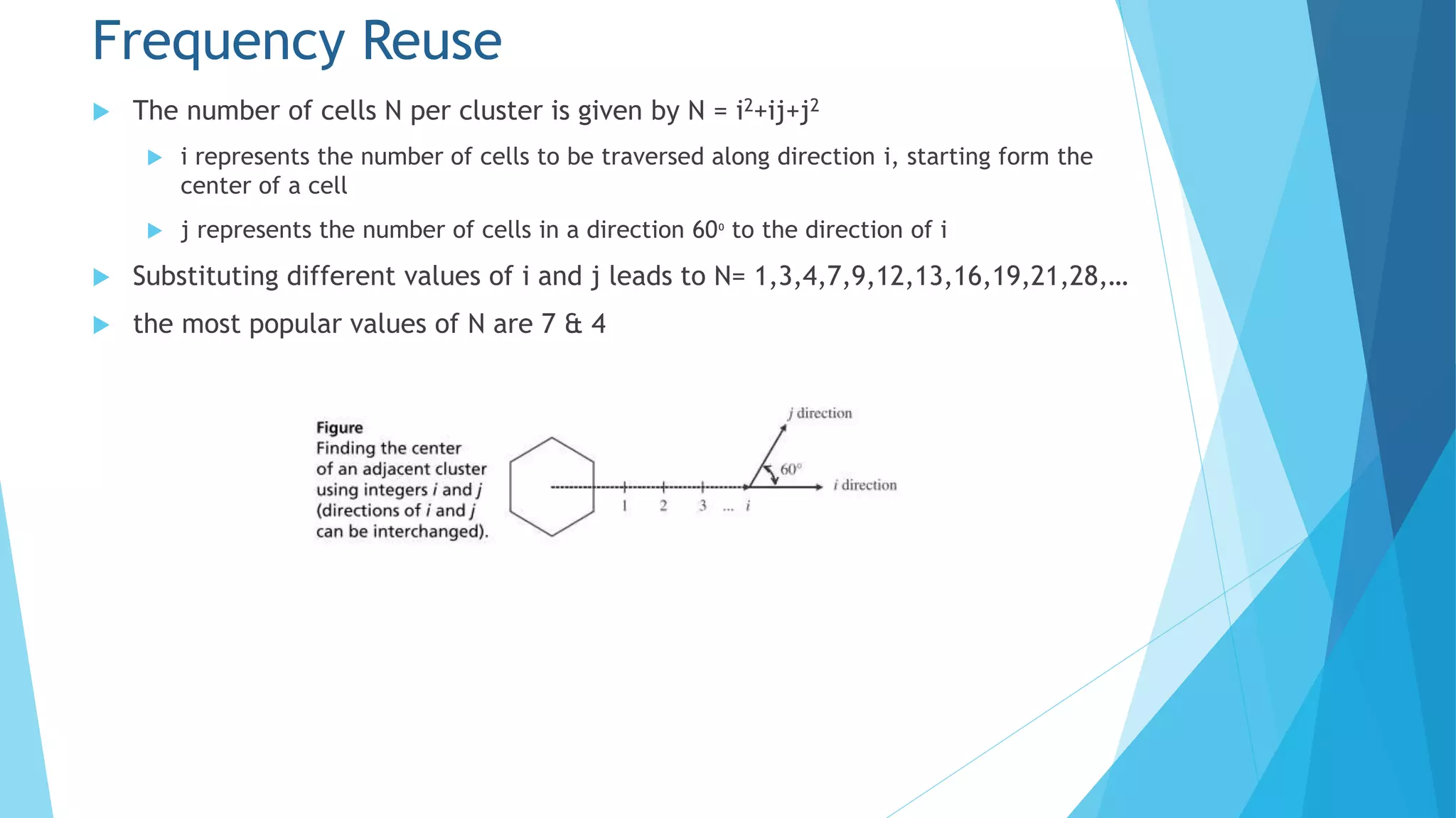
![ For a case j=1 with a given N & integer i is fixed then we get from the
equation
N = i2+ij+j2 = i2+i+1 (20)
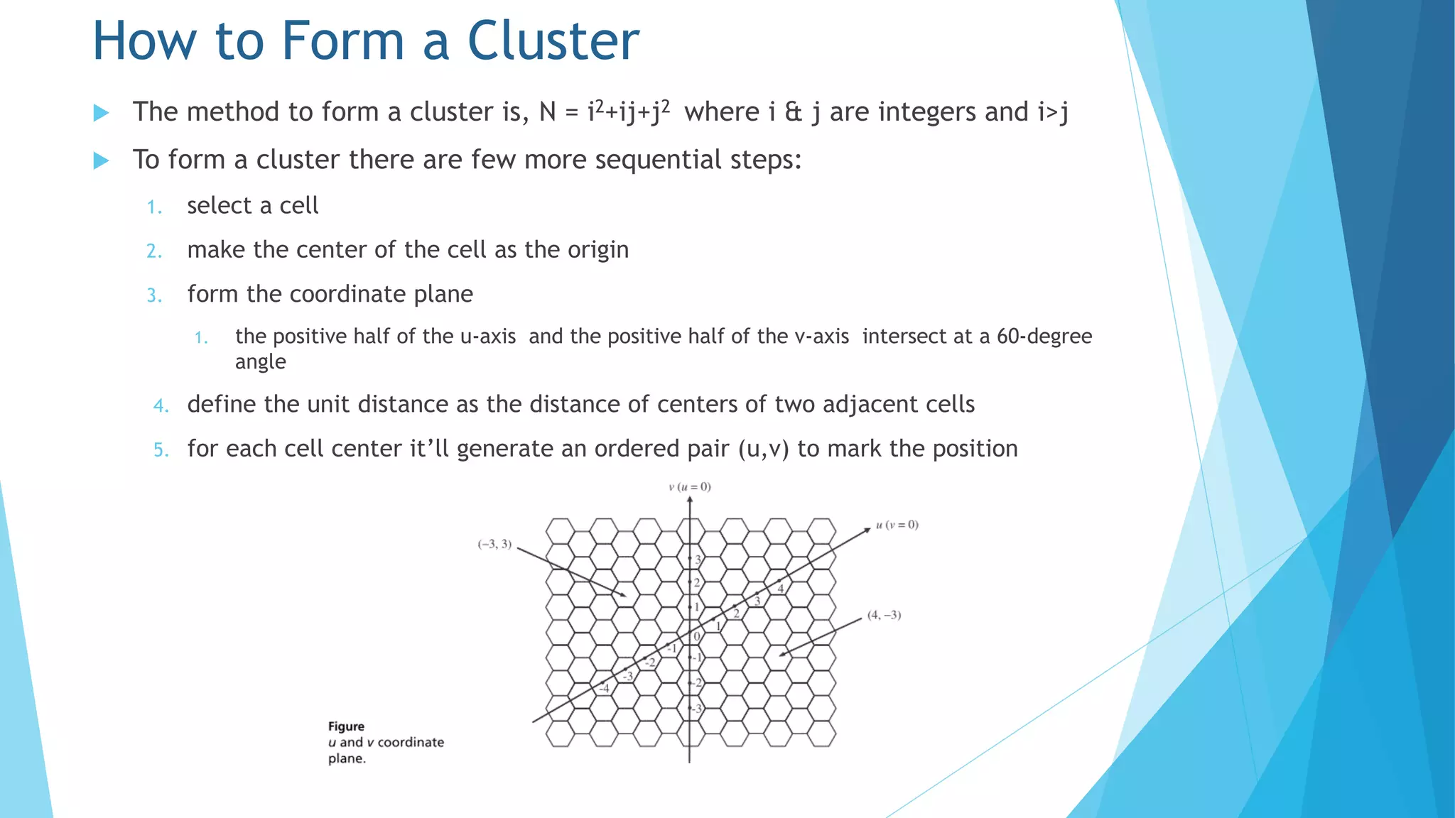
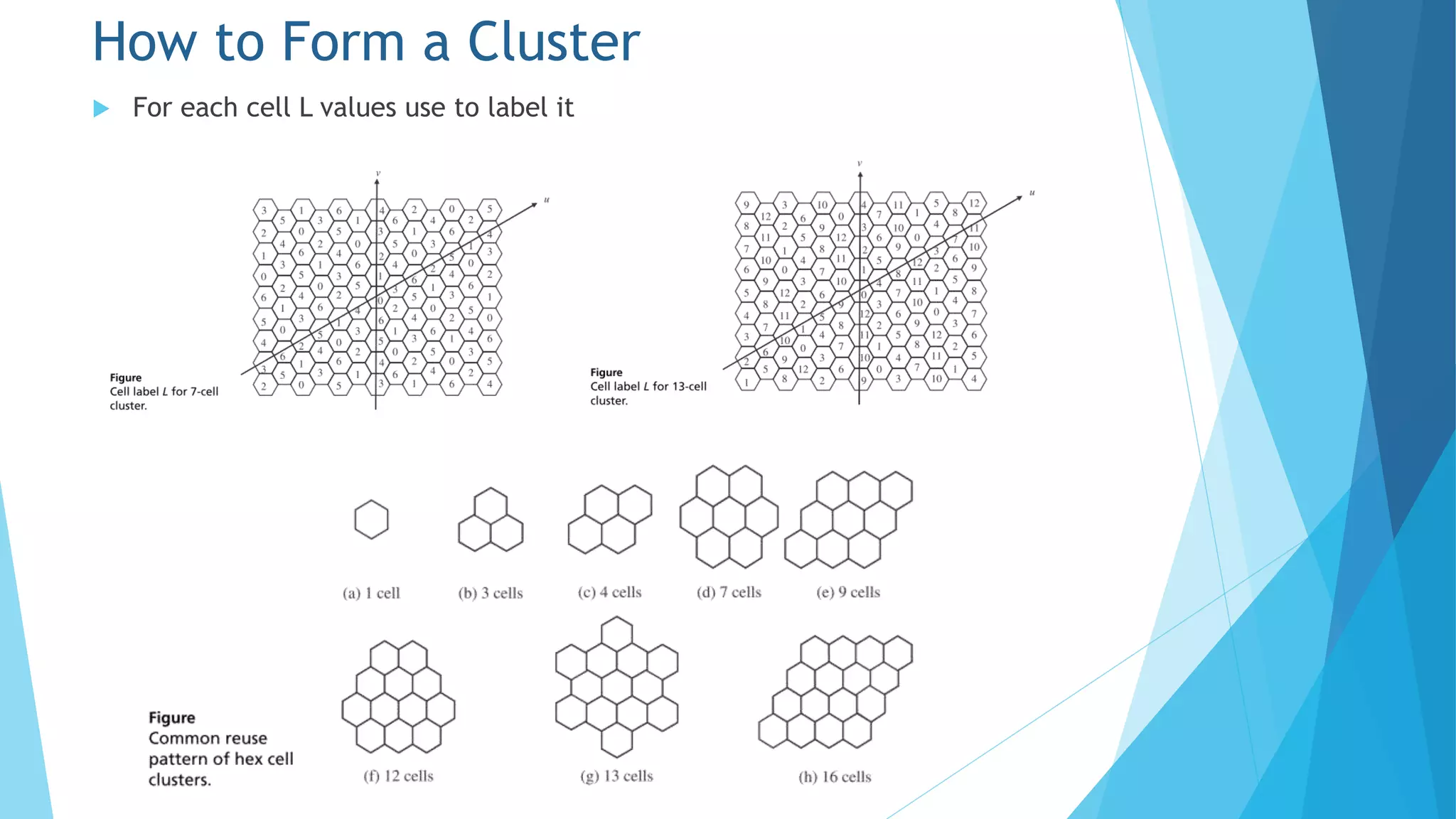
Then using L = [(i+1)u+v]modN (21)
The cells with labels from 0 through N-1 form a cluster of N cells by using the
above equations
The cells with the same band can use same frequency
For example if given N=7 & by using equation (20) we get i=2 & from equation
(21) we can get L=(3u+v) mod 7
For center’s position (u,v) we can compute label L
How to Form a Cluster](https://image.slidesharecdn.com/chapter5-151027031403-lva1-app6892/75/Chapter-5-Cellular-Concepts-16-2048.jpg)

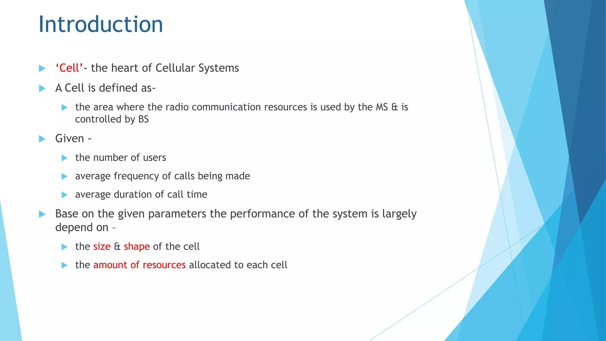
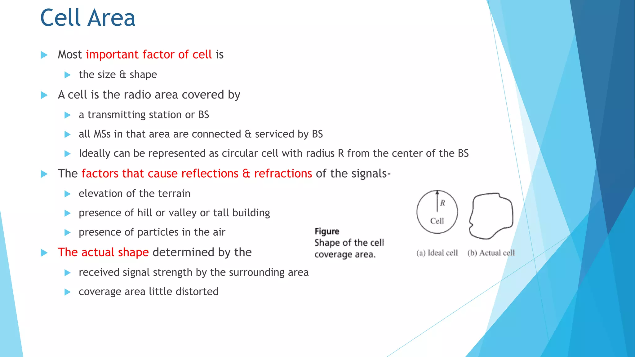
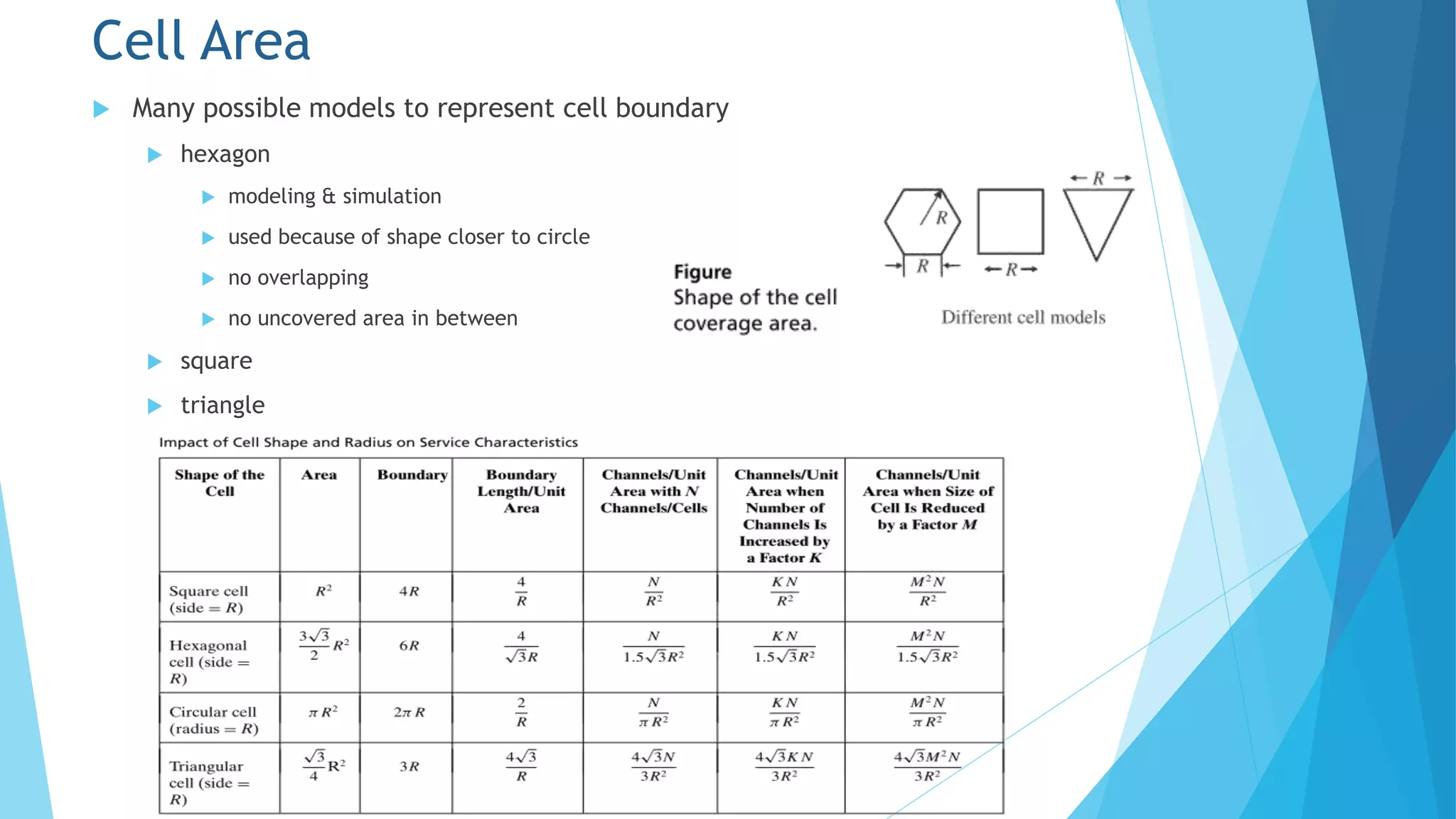
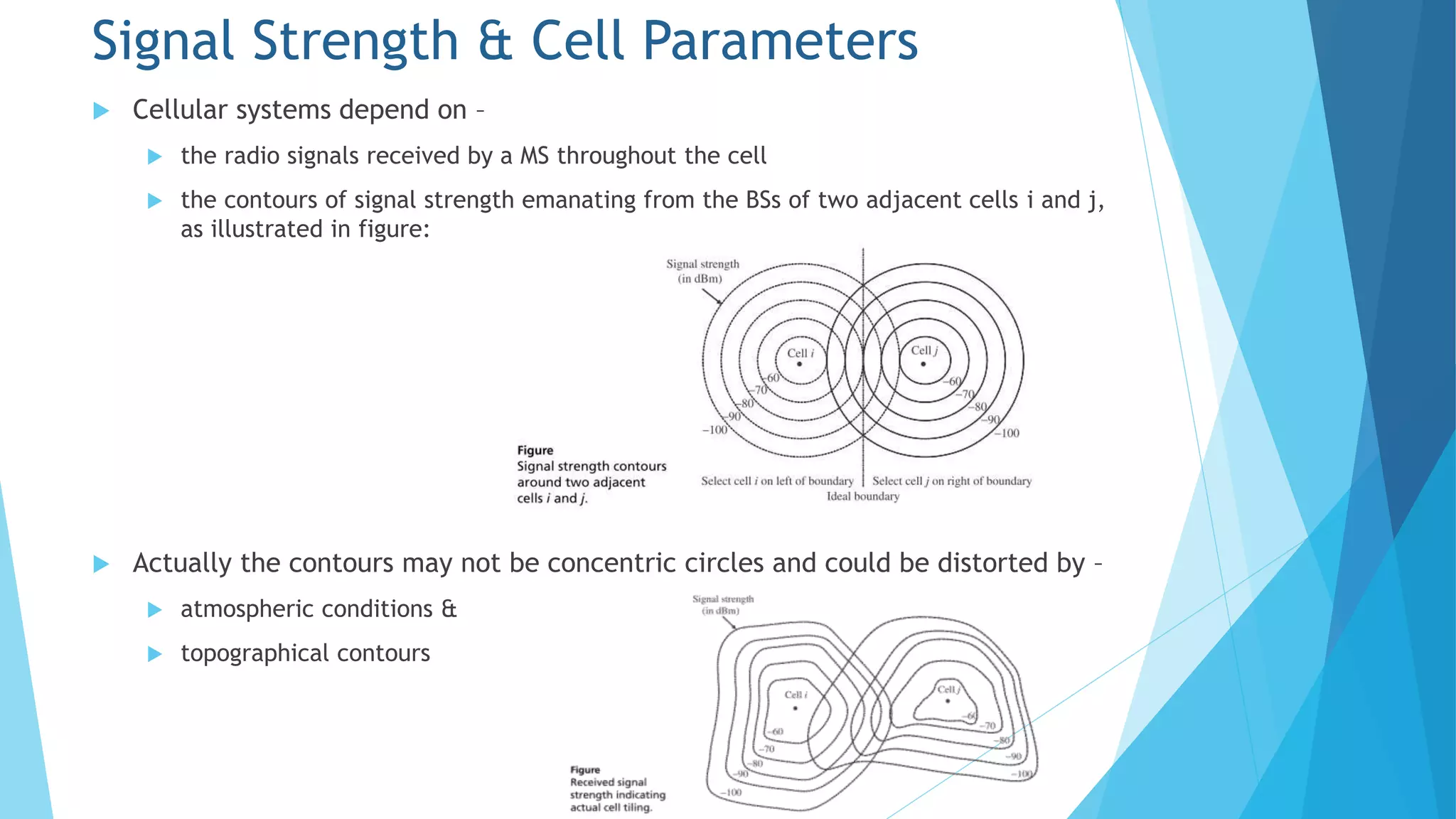
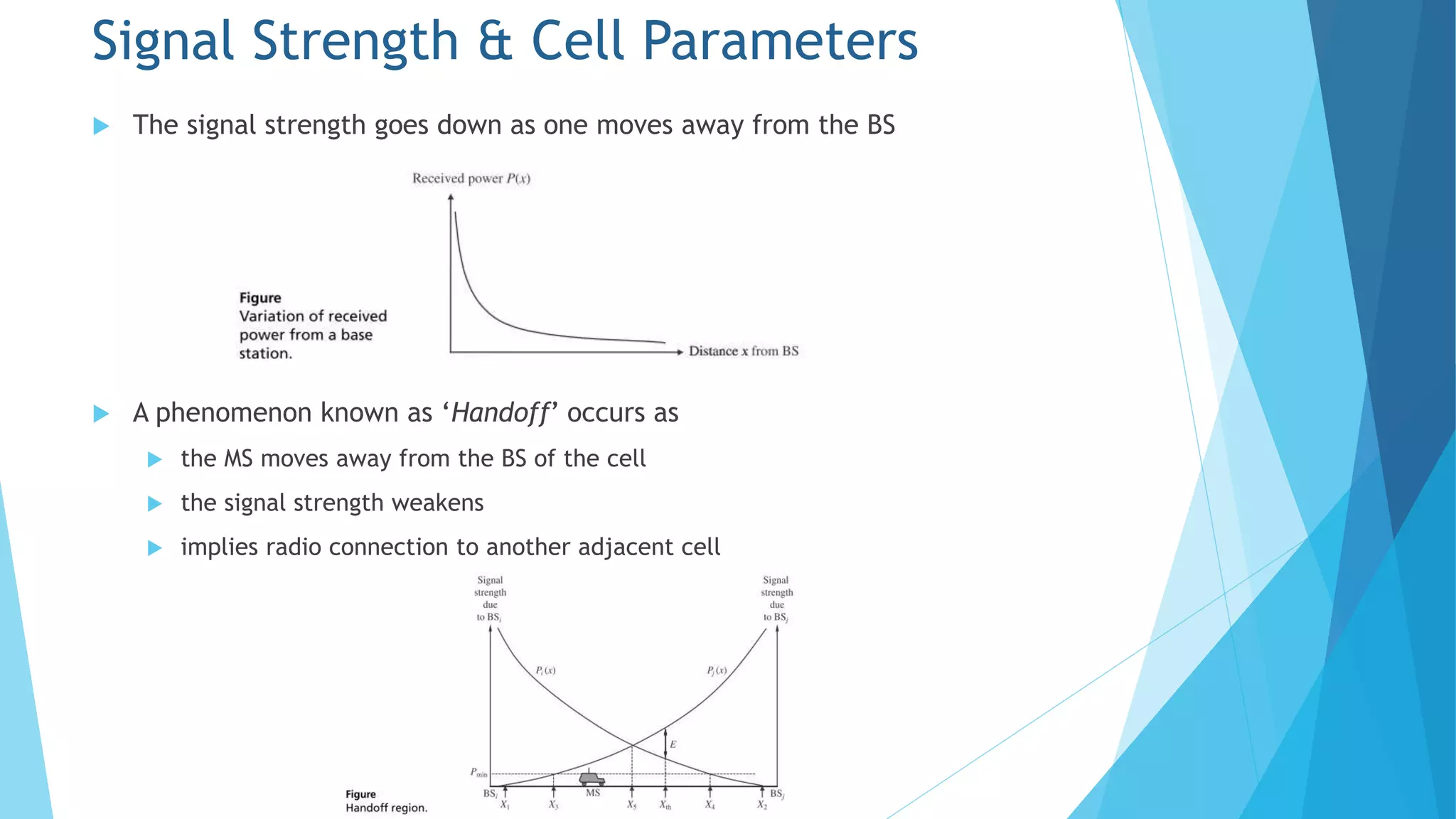
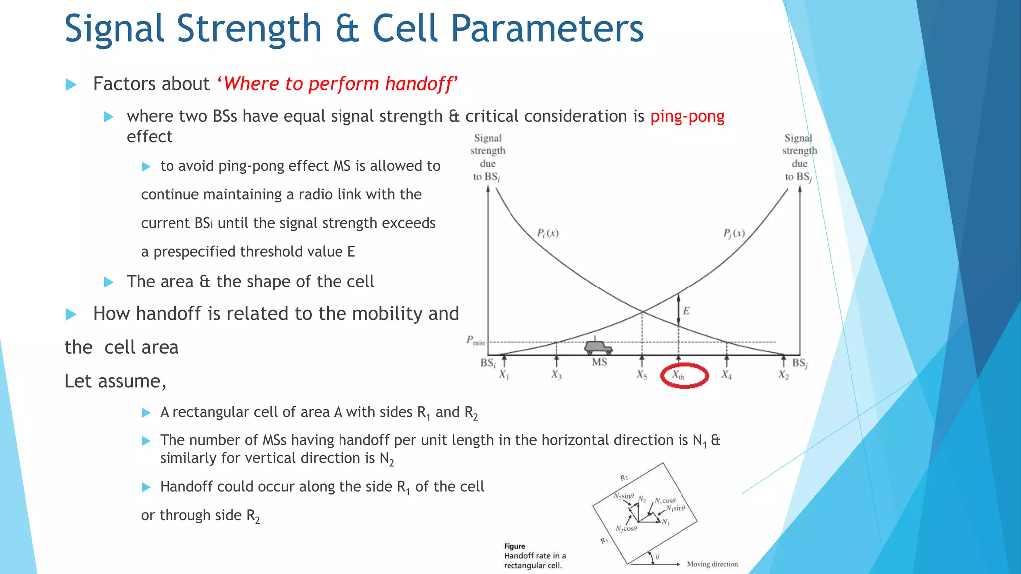
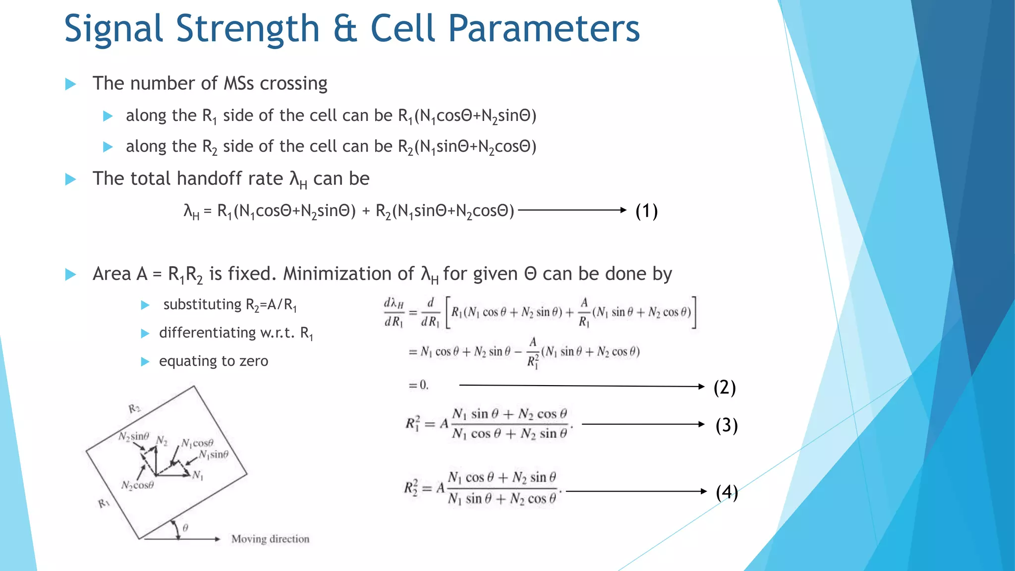
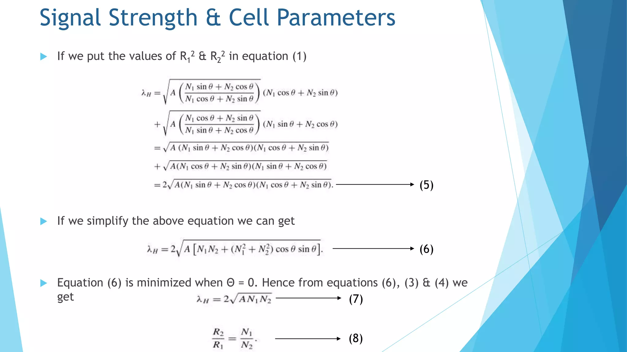
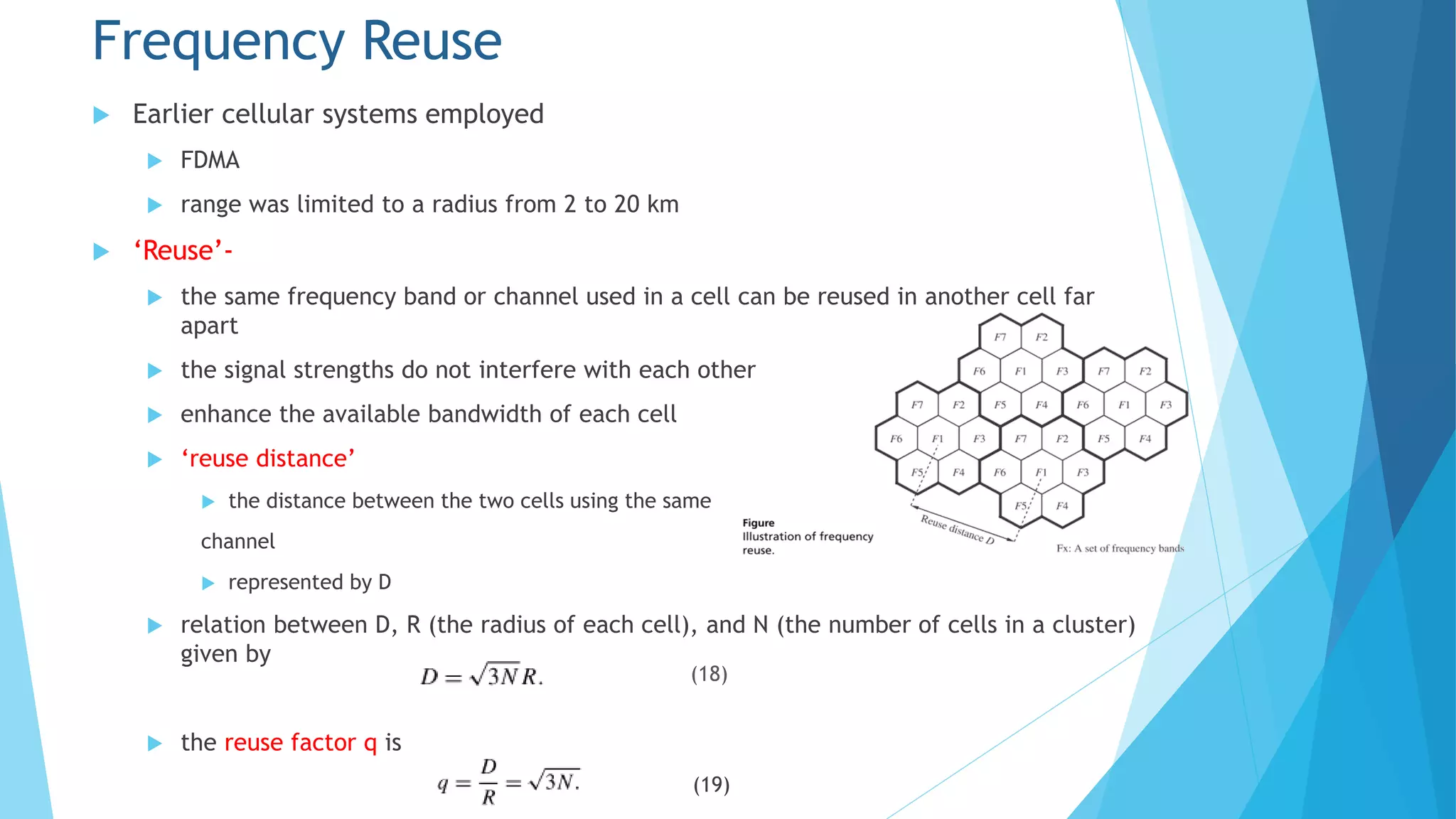
Chapter 5 discusses the cellular concept in radio communications, emphasizing the importance of cell size and shape in system performance. It covers the parameters affecting signal strength, handoff processes, traffic load, and strategies like frequency reuse, cell splitting, and sectoring to manage interference and optimize resource usage. The chapter provides mathematical models to analyze call arrival rates and blocking probabilities in cellular networks.