This document provides information about a Mechanical Working Drawing course, including:
- The instructors, textbook, and intended learning outcomes which are to understand machine assembly drawings, distinguish between working and assembly drawings, and professionally create drawings according to standards.
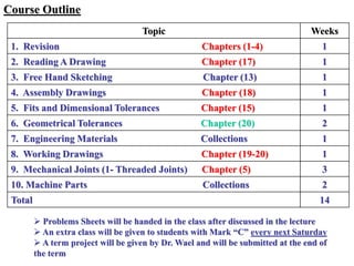
- The course outline covers topics like reading drawings, freehand sketching, assembly drawings, fits and tolerances, and threaded joints over 14 weeks.
- Assessment includes measuring achieved objectives, identifying areas for improvement, and completing term projects and problem sheets.