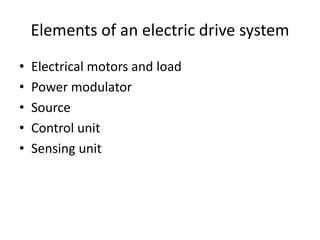
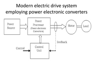
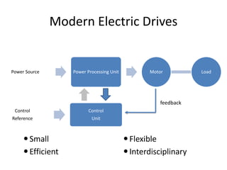
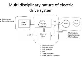
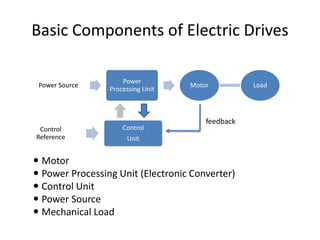
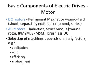
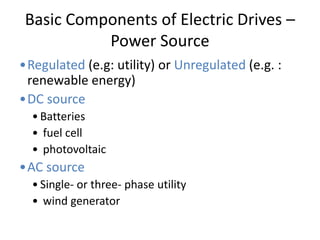
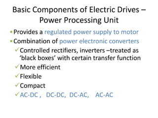
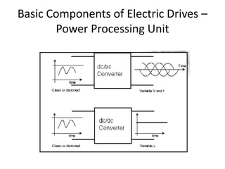
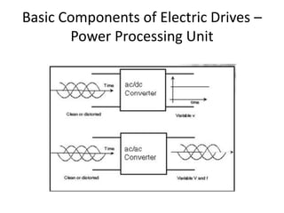
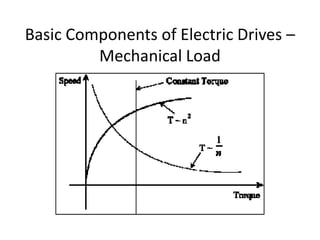
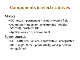
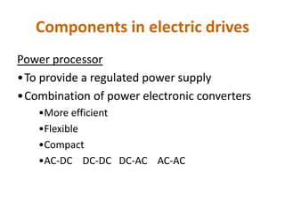
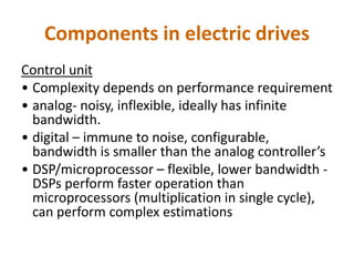
C.VENKATESH KUMAR M.E.,
Assistant Professor / EEE
St. Joseph’s College of Engg, Chennai.
EE6351 - Electrical Drives and Controls
UNIT I INTRODUCTION 8(L)
Basic Elements – Types of Electric Drives – factors influencing the choice of electrical drives –
heating and cooling curves – Loading conditions and classes of duty – Selection of power rating
for drive motors with regard to thermal overloading and Load variation factors.
UNIT II DRIVE MOTOR CHARACTERISTICS 9(L)
Mechanical characteristics – Speed-Torque characteristics of various types of load and drive
motors – Braking of Electrical motors – DC motors: Shunt, series and compound - single phase
and three phase induction motors.
UNIT III STARTING METHODS 8(L)
Types of D.C Motor starters – Typical control circuits for shunt and series motors – Three phase
squirrel cage and slip ring induction motors.
UNIT IV CONVENTIONAL AND SOLID STATE SPEED CONTROL OF D.C. DRIVES 10(L)
Speed control of DC series and shunt motors – Armature and field control, Ward-Leonard control
system - Using controlled rectifiers and DC choppers –applications.
UNIT V CONVENTIONAL AND SOLID STATE SPEED CONTROL OF A.C. DRIVES 10(L)
Speed control of three phase induction motor – Voltage control, voltage / frequency control, slip
power recovery scheme – Using inverters and AC voltage regulators – applications.
TEXT BOOKS
1. VEDAM SUBRAHMANIAM, “Electric Drives (concepts
and applications)”, Tata McGraw-Hill, 2001
2. NAGRATH.I.J. & KOTHARI.D.P, “Electrical Machines”,
Tata McGraw-Hill, 1998
REFERENCE BOOKS
1. PILLAI.S.K “A first course on Electric drives”, Wiley
Eastern Limited, 1998
2. M.D.SINGH, K.B.KHANCHANDANI, “Power
Electronics”, Tata McGraw-Hill, 1998
3 H.Partab, “Art and Science and Utilisation of
electrical energy”, Dhanpat Rai and Sons, 1994
4 Gopal K Dubey, ” Fundamentals of Electric Drives”
5 P.K Sen, ”Electric Drives”
UNIT I INTRODUCTION 8(L)
Basic Elements – Types of Electric
Drives – factors influencing the choice
of electrical drives – heating and
cooling curves – Loading conditions
and classes of duty – Selection of
power rating for drive motors with
regard to thermal overloading and
Load variation factors.
Electrical Drives?
A drive consists of various system
combined together for the purpose
of motion control or movement
control. Especially the drives which
employ electric motors for motion
control are known as Electrical
drives.
Electrical Drives
Drives are systems employed for motion control
Require prime movers
Drives that employ electric motors as
prime movers are known as Electrical Drives
Electrical Drives
• About 50% of electrical energy used for drives
• Can be either used for fixed speed or variable speed
• 75% - constant speed, 25% variable speed (expanding)
Example on VSD application
motor pump
valve
Supply
Constant speed Variable Speed Drives
Power
In
Power loss
Mainly in valve
Power out
Example on VSD application
motor pump
valve
Supply
motor
PEC pump
Supply
Constant speed Variable Speed Drives
Power
In
Power loss
Power out
Power loss
Mainly in valve
Power out
Power
In
Power loss
Mainly in valve
Power out
motor pump
valve
Supply
motor
PEC pump
Supply
Constant speed Variable Speed Drives
Example on VSD application
Power
In
Power loss
Power
In
Power out
Electric Drives Application
• Single-Motor,
Single-Load Drives
– Most common
– Eg: electric saws,
drills, fans,
washers, blenders,
disk-drives, electric
cars.
Electric Drives Application
• Multimotor
Drives
– Several motors,
single mechanical
load
– Complex drive
functions
– Eg: assembly
lines, robotics,
military airplane
actuation.
Application of electrical drives
• Paper mills
• Electric traction
• Cement mills
• Steel mills
Definition of Electrical Drives
• Drives – system employed
for motion control
• Motion control requires
prime movers
• Electrical Drives – Drives
that employ Electric
Motors as prime movers
Electrical Drives -> Electric
Motor as Prime Mover
Prime Mover
Drives -> Motion Control
Conventional variable speed electrical
drive system
Conventional Electric Drives
Disadvantage :
Bulky
Expensive
Inefficient
Complex
Elements of an electric drive system
• Electrical motors and load
• Power modulator
• Source
• Control unit
• Sensing unit
Modern electric drive system
employing power electronic converters
Modern Electric Drives
Small
Efficient
Flexible
Interdisciplinary
Power Source Power Processing Unit Motor Load
Control
Reference
Control
Unit
feedback
Multi disciplinary nature of electric
drive system
Basic Components of Electric Drives
 Motor
 Power Processing Unit (Electronic Converter)
 Control Unit
 Power Source
 Mechanical Load
Power Source
Power
Processing Unit
Motor Load
Control
Reference
Control
Unit
feedback
Basic Components of Electric Drives -
Motor
•DC motors - Permanent Magnet or wound-field
(shunt, separately excited, compound, series)
•AC motors – Induction, Synchronous (wound –
rotor, IPMSM, SPMSM), brushless DC
•Selection of machines depends on many factors,
e.g.:
• application
• cost
• efficiency
• environment
Basic Components of Electric Drives –
Power Source
•Regulated (e.g: utility) or Unregulated (e.g. :
renewable energy)
•DC source
• Batteries
• fuel cell
• photovoltaic
•AC source
• Single- or three- phase utility
• wind generator
Basic Components of Electric Drives –
Power Processing Unit
•Provides a regulated power supply to motor
•Combination of power electronic converters
Controlled rectifiers, inverters –treated as
‘black boxes’ with certain transfer function
More efficient
Flexible
Compact
AC-DC , DC-DC, DC-AC, AC-AC
Basic Components of Electric Drives –
Power Processing Unit
Basic Components of Electric Drives –
Power Processing Unit
Basic Components of Electric Drives –
Control Unit
• Supervise operation
• Enhance overall performance and stability
• Complexity depends on performance requirement
• Analog Control – noisy, inflexible, ideally infinite bandwidth
• Digital Control – immune to noise, configurable, smaller
bandwidth
• DSP/microprocessor – flexible, lower bandwidth, real-time
• DSPs perform faster operation than microprocessors
(multiplication in single cycle), can perform complex
estimations
Basic Components of Electric Drives –
Mechanical Load
• Wide variation of Torque-speed (T-)
characteristics
• Load torque is function of speed
• where k = integer or fraction
• Mechanical power of load:
• and
k
m
L
T 

m
L
T
P 
 m
m n
60
2
 
Angular speed
in rad/s
Speed
in rpm
Basic Components of Electric Drives –
Mechanical Load
Components in electric drives
Motors
• DC motors - permanent magnet – wound field
• AC motors – induction, synchronous (IPMSM,
SMPSM), brushless DC
• Applications, cost, environment
Power sources
• DC – batteries, fuel cell, photovoltaic - unregulated
• AC – Single- three- phase utility, wind generator –
unregulated
Components in electric drives
Power processor
•To provide a regulated power supply
•Combination of power electronic converters
•More efficient
•Flexible
•Compact
•AC-DC DC-DC DC-AC AC-AC
Components in electric drives
Control unit
• Complexity depends on performance requirement
• analog- noisy, inflexible, ideally has infinite
bandwidth.
• digital – immune to noise, configurable,
bandwidth is smaller than the analog controller’s
• DSP/microprocessor – flexible, lower bandwidth -
DSPs perform faster operation than
microprocessors (multiplication in single cycle),
can perform complex estimations
Some Applications of Electric Drives
Conveyors, elevators, escalators, lifts
Paper and pulp mills; textile mills
Steel mills, sugar mills, coal mining
Pumps, fans, compressors
Plant automation
Flexible manufacturing systems
Spindles and servos
Appliances and power tools
Cement kilns
Automotive applications
The advantage of an electric drive
system
• Flexible control characteristic – This is particularly true when
power electronic converters are employed where the dynamic
and steady state characteristics of the motor can be controlled by
controlling the applied voltage or current.
• High efficiency (no load losses are less), lower noise, low
maintenance requirements and cleaner operation (pollution free)
• Control characteristic can be manipulated as per requirements
• Availability of simple and easy speed control methods
• Electric braking can be employed in easy manner
• The variety of electric drives with wide range of speed, power and
torque ratings are available.
• Electric energy is easy to be transported.
• Started immediately and fully loaded immediately
• They have short time overload capacity.
Torque-Speed Quadrant of Operation
m
Te
Te
m
Te
m
Te
m

T
•Direction of positive (forward)
speed is arbitrary chosen
•Direction of positive torque will
produce positive (forward) speed
Quadrant 1
Forward motoring
Quadrant 2
Forward braking
Quadrant 3
Reverse motoring
Quadrant 4
Reverse braking
Classification of Electric Drives
• According to Mode of Operation
– Continuous duty drives
– Short time duty drives
– Intermittent duty drives
• According to Means of Control
– Manual
– Semi automatic
– Automatic
• According to Number of machines
– Individual drive
– Group drive
– Multi-motor drive
Classification of Electric Drives
• According to Dynamics and Transients
– Uncontrolled transient period
– Controlled transient period
• According to Methods of Speed Control
– Reversible and non-reversible uncontrolled constant
speed.
– Reversible and non-reversible step speed control.
– Variable position control.
– Reversible and non-reversible smooth speed control.
The elements of an electric drive
system
• Group drive
• Individual drive
• Multimotor drive
Group Electric Drive
• This drive consists of a single motor, which drives one
or more line shafts supported on bearings. The line
shaft may be fitted with either pulleys and belts or
gears, by means of which a group of machines or
mechanisms may be operated. It is also some times
called as SHAFT DRIVES.
• Advantages
A single large motor can be used instead of number of
small motors
• Disadvantages
There is no flexibility. If the single motor used develops
fault, the whole process will be stopped.
Individual Electric Drive
• In this drive each individual machine is driven by a
separate motor. This motor also imparts motion to
various parts of the machine.
• Electric motor is used for transmitting motion to
various parts or mechanisms belonging to single
equipment.
• This motor also imparts motion to various other parts
of the system.
• Eg. Single spindle drilling machine(lathes).
• Lathe – the motor rotates the spindle, moves the feed
and also with the help of gears, transmits motion to
lubricating and cooling pumps.
Multi Motor Electric Drive
In this drive system, there are several drives, each of which
serves to actuate one of the working parts of the drive
mechanisms.
• Eg. Travelling cranes – there are three motors, one for
hoisting, another for long travel motion and the third for
cross travel motion.
• Crane operator coordinate all three functions.
• Electric locomotive traction drive – 4-8 motors.
E.g.: Complicated metal cutting machine tools
Paper making industries,
Rolling machines etc.
The types of electrical drives
• DC drives
• AC drives
DC Drives AC Drives
The commutator makes the
motor bulky, costly and heavy
Motors are inexpensive, particular
squirrel cage motor
The converter technology is
well established. The power
converter is simple and
inexpensive
The inverter technology is still
being developed. The power circuit
of the converter and its control are
simple
Line commutation of the
converter is used
Forced commutation is used with
induction motors. Sometimes
machine commutation may be used
with synchronous motors
Fast response and wide speed
range smooth control
With solid state converter the speed
range is wide. With conventional
methods it is stepped and limited
Small power/weight ratio Large power /weight ratio
Cost does not depend on the
solid state converter
Solid state converter employed also
decides the cost
Overview of AC and DC drives
Extracted from Boldea & Nasar
Overview of AC and DC drives
DC motors: Regular maintenance, heavy, expensive, speed limit
Easy control, decouple control of torque and flux
AC motors: Less maintenance, light, less expensive, high speed
Coupling between torque and flux – variable spatial
angle between rotor and stator flux
Three methods of operation for
electrics drive
• Steady state
• Acceleration including starting
• Deceleration including stopping
Factors affecting the selection of
electric drives
• Efficiency,
• Braking,
• Limits of speed range,
• starting requirements,
• power factor,
• load factor,
• availability of supply,
• effects of supply
variations,
• economical aspects,
• reliability of operation,
• environmental effects.
Factors affect the selection of different
configuration of electrical drive system
• Torque and speed profile - determine the
ratings of converters and the quadrant of
operation required.
• Capital and running cost – Drive systems will
vary in terms of start-up cost and running
cost, e.g. maintenance
• Space and weight restrictions
• Environment and location
Selecting a Drive
There can be several factors that affect the
selection of different configuration of electrical
drive system such as
a) Torque and speed profile - determine the
ratings of converters and the quadrant of
operation required.
b) Capital and running cost – Drive systems will
vary in terms of start-up cost and running cost,
e.g. maintenance
c) Space and weight restrictions
d) Environment and location
Selecting a Drive
• Overall Considerations
• Motor limitations
• Thermal considerations
Choice (or) Selection of Electrical
Drives
Choice of an electric drive depends on a number of factors. Some of the
important factors are.
1. Steady State Operating conditions requirements
– Nature of speed torque characteristics, speed regulation, speed range, efficiency, duty
cycle, quadrants of operation, speed fluctuations if any, ratings etc
2. Transient operation requirements
– Values of acceleration and deceleration, starting, braking and reversing performance.
3. Requirements related to the source
– Types of source and its capacity, magnitude of voltage, voltage fluctuations, power
factor, harmonics and their effect on other loads, ability to accept regenerative power
4. Capital and running cost, maintenance needs life.
5. Space and weight restriction if any.
6. Environment and location.
7. Reliability.
Heating and cooling curve
The size and rating of a motor to be used as
a drive element in a particular appln
depends upon
• Heating effects in the motors
• Loading conditions and classes of duty
• Load inertia or inertias
• Environment conditions
Heating effects
• When a motor operates, heat is produced due to losses
inside the machine and its temp rises.
• As the temperature increases beyond(exceeds) ambient
value, a portion of heat produced, flows out to the
surrounding medium.
• The amount of outflow of heat is a function of temp rise
of motor above the ambient value.
• As motor temp rises, the heat outflow increases and
equilibrium ultimately sets in when the heat generated
becomes equal to heat dissipated to surrounding
medium.
• Steady state temperature depends on power loss, which
in turn depends on the output power of the machine.
• Steady state temperature is not same at various parts of
the machine.(winding – high – loss density is high,
dissipation is slow.
• Too complex to predict the accuracy of heat flow and
temperature distribution.
• Direction of heat flow does not remain same at all load
conditions.
• At no-load and lightly loaded condition ,heat flows from
iron parts to windings due to temp gradient.
• When load increases, heat generation in the winding is
greater than iron core.
Reference : Electric Drives by Vedam Subramaniyam
Page num: 461-467.
Heating and cooling curves
simplifications
• Homogeneous body – uniform temp gradient.
• At all the points at which heat is generated have the
same temp.
• At all the points at which heat is dissipated to
cooling medium have the same temp.
• Heat dissipation is directly proportional to the
difference of temp of the body and surrounding
medium. No heat is radiated.
• Rate of dissipation of heat is constant at all temp.
CLASSES OF DUTY
• The rating of motor selected from the viewpoint of
heating depends on the load conditions to which it
is subjected.
• There are eight types of classes of duty.
• REF – S.K PILLAI (142-146)
Motor Duty Types
• Actual operating conditions are often of a
more irregular nature than those
corresponding to any of the standard duty
types. When choosing and rating a motor it is
necessary to decide on the type of duty that
corresponds best to the thermal stresses that
are expected to occur in practice.
Motor Duty Types
• Standard types of duty classes
– Continuous Duty
– Short Time Duty
– Intermittent periodic Duty
– Intermittent periodic Duty with Starting
– Intermittent periodic Duty with starting and Braking
– Continuous duty with intermittent Periodic loading
– Continuous Duty with starting and Braking
– Continuous Duty with periodic speed changes
Continuous Duty
Continuous duty denotes Operation at constant load and long enough
for thermal equilibrium to be reached.
Short Time Duty
Operation at constant load for a given
time, that is shorter than the time
needed to reach thermal equilibrium,
followed by a rest and de-energised
period. The de-energisation period
should be long enough to allow the
motor to reach a temperature that
does not deviate from the temperature
of the cooling medium.
Intermittent Duty
A sequence of identical duty cycles,
where each cycle is in two parts, one at
constant load and the other at rest and
de-energised. In this type of duty the
starting current has no significant
effect on the temperature rise. The
duty cycle is too short for thermal
equilibrium to be reached.
Intermittent Duty with Starting
A sequence of individual duty cycles,
where each cycle consists of a start that
is sufficiently long to have a significant
effect on the motor temperature, a
period of constant load and a period at
rest and de-energised. In this type of
duty the starting current is insignificant
on the temperature rise. The duty cycles
are too short for thermal equilibrium to
be reached.
Intermittent Duty with starting and
Braking
A sequence of identical duty cycles,
where each cycle consists of a start,
a period at constant load followed
by rapid electrical braking, and a
rest and de-energised period. The
duty cycle is too short for thermal
equilibrium to be reached.
Continuous duty with intermittent
Periodic loading
A sequence of identical duty cycles,
where each cycle is in two parts,
one at constant load and the other
at no load, no rest and no de-
energised period. The duty cycles
are too short for thermal
equilibrium conditions to be
reached.
Continuous Duty with starting and
Braking
A sequence of identical duty cycles,
where each cycle consists of a start
and a period at constant load,
followed by electrical braking, no
rest and de-energised period. The
duty cycles are too short for thermal
equilibrium conditions to be
reached.
Continuous Duty with periodic speed
changes
This duty consists of a period
of running at a different period
of running at diff speed and load,
again both operating periods are
too short for thermal
equilibrium conditions to be reached.
SELECTION OF POWER RATING OF MOTORS
The calculation of motor rating for various duty
cycles can be classified as:
• Continuous duty and constant load.
• Continuous duty and variable load.
• Short time rating (or) short time duty.
Continuous duty and constant load
• For a drive motor which is driving a constant
load for sufficiently longer period till it reaches
thermal equilibrium, its rating must be
sufficient to drive it without exceeding the
specified temp.
• It specifies the max load that the motor can
take over a period of time without exceeding
the temp rise.
• The motor should carry momentary overloads.
• So, select the motor Rating slightly more than
the power required by the load.
Continuous duty and variable load
• temp changes continuously when load is variable
• Difficult to select the motor rating as per heating
• Analytical study is highly complicated when it has
irregular load and large num of steps.
• Difficult to Select the motor capacity thr the
analysis of load diagram – lack of accuracy.
• In otherwords it is not correct to select the motor
according to the low and highest value.
• Necessary to adopt suitable methods for
determination of power rating.
Methods
• Method of average losses
• Equivalent current method
• Equivalent torque method
• Equivalent power method
UNIT I Electric Drives and   control.ppt

UNIT I Electric Drives and control.ppt

  • 1.
    C.VENKATESH KUMAR M.E., AssistantProfessor / EEE St. Joseph’s College of Engg, Chennai. EE6351 - Electrical Drives and Controls
  • 2.
    UNIT I INTRODUCTION8(L) Basic Elements – Types of Electric Drives – factors influencing the choice of electrical drives – heating and cooling curves – Loading conditions and classes of duty – Selection of power rating for drive motors with regard to thermal overloading and Load variation factors. UNIT II DRIVE MOTOR CHARACTERISTICS 9(L) Mechanical characteristics – Speed-Torque characteristics of various types of load and drive motors – Braking of Electrical motors – DC motors: Shunt, series and compound - single phase and three phase induction motors. UNIT III STARTING METHODS 8(L) Types of D.C Motor starters – Typical control circuits for shunt and series motors – Three phase squirrel cage and slip ring induction motors. UNIT IV CONVENTIONAL AND SOLID STATE SPEED CONTROL OF D.C. DRIVES 10(L) Speed control of DC series and shunt motors – Armature and field control, Ward-Leonard control system - Using controlled rectifiers and DC choppers –applications. UNIT V CONVENTIONAL AND SOLID STATE SPEED CONTROL OF A.C. DRIVES 10(L) Speed control of three phase induction motor – Voltage control, voltage / frequency control, slip power recovery scheme – Using inverters and AC voltage regulators – applications.
  • 3.
    TEXT BOOKS 1. VEDAMSUBRAHMANIAM, “Electric Drives (concepts and applications)”, Tata McGraw-Hill, 2001 2. NAGRATH.I.J. & KOTHARI.D.P, “Electrical Machines”, Tata McGraw-Hill, 1998 REFERENCE BOOKS 1. PILLAI.S.K “A first course on Electric drives”, Wiley Eastern Limited, 1998 2. M.D.SINGH, K.B.KHANCHANDANI, “Power Electronics”, Tata McGraw-Hill, 1998 3 H.Partab, “Art and Science and Utilisation of electrical energy”, Dhanpat Rai and Sons, 1994 4 Gopal K Dubey, ” Fundamentals of Electric Drives” 5 P.K Sen, ”Electric Drives”
  • 4.
    UNIT I INTRODUCTION8(L) Basic Elements – Types of Electric Drives – factors influencing the choice of electrical drives – heating and cooling curves – Loading conditions and classes of duty – Selection of power rating for drive motors with regard to thermal overloading and Load variation factors.
  • 5.
    Electrical Drives? A driveconsists of various system combined together for the purpose of motion control or movement control. Especially the drives which employ electric motors for motion control are known as Electrical drives.
  • 6.
    Electrical Drives Drives aresystems employed for motion control Require prime movers Drives that employ electric motors as prime movers are known as Electrical Drives
  • 7.
    Electrical Drives • About50% of electrical energy used for drives • Can be either used for fixed speed or variable speed • 75% - constant speed, 25% variable speed (expanding)
  • 8.
    Example on VSDapplication motor pump valve Supply Constant speed Variable Speed Drives Power In Power loss Mainly in valve Power out
  • 9.
    Example on VSDapplication motor pump valve Supply motor PEC pump Supply Constant speed Variable Speed Drives Power In Power loss Power out Power loss Mainly in valve Power out Power In
  • 10.
    Power loss Mainly invalve Power out motor pump valve Supply motor PEC pump Supply Constant speed Variable Speed Drives Example on VSD application Power In Power loss Power In Power out
  • 11.
    Electric Drives Application •Single-Motor, Single-Load Drives – Most common – Eg: electric saws, drills, fans, washers, blenders, disk-drives, electric cars.
  • 12.
    Electric Drives Application •Multimotor Drives – Several motors, single mechanical load – Complex drive functions – Eg: assembly lines, robotics, military airplane actuation.
  • 13.
    Application of electricaldrives • Paper mills • Electric traction • Cement mills • Steel mills
  • 14.
    Definition of ElectricalDrives • Drives – system employed for motion control • Motion control requires prime movers • Electrical Drives – Drives that employ Electric Motors as prime movers Electrical Drives -> Electric Motor as Prime Mover Prime Mover Drives -> Motion Control
  • 15.
    Conventional variable speedelectrical drive system
  • 16.
    Conventional Electric Drives Disadvantage: Bulky Expensive Inefficient Complex
  • 17.
    Elements of anelectric drive system • Electrical motors and load • Power modulator • Source • Control unit • Sensing unit
  • 18.
    Modern electric drivesystem employing power electronic converters
  • 19.
    Modern Electric Drives Small Efficient Flexible Interdisciplinary PowerSource Power Processing Unit Motor Load Control Reference Control Unit feedback
  • 20.
    Multi disciplinary natureof electric drive system
  • 21.
    Basic Components ofElectric Drives  Motor  Power Processing Unit (Electronic Converter)  Control Unit  Power Source  Mechanical Load Power Source Power Processing Unit Motor Load Control Reference Control Unit feedback
  • 22.
    Basic Components ofElectric Drives - Motor •DC motors - Permanent Magnet or wound-field (shunt, separately excited, compound, series) •AC motors – Induction, Synchronous (wound – rotor, IPMSM, SPMSM), brushless DC •Selection of machines depends on many factors, e.g.: • application • cost • efficiency • environment
  • 23.
    Basic Components ofElectric Drives – Power Source •Regulated (e.g: utility) or Unregulated (e.g. : renewable energy) •DC source • Batteries • fuel cell • photovoltaic •AC source • Single- or three- phase utility • wind generator
  • 24.
    Basic Components ofElectric Drives – Power Processing Unit •Provides a regulated power supply to motor •Combination of power electronic converters Controlled rectifiers, inverters –treated as ‘black boxes’ with certain transfer function More efficient Flexible Compact AC-DC , DC-DC, DC-AC, AC-AC
  • 25.
    Basic Components ofElectric Drives – Power Processing Unit
  • 26.
    Basic Components ofElectric Drives – Power Processing Unit
  • 27.
    Basic Components ofElectric Drives – Control Unit • Supervise operation • Enhance overall performance and stability • Complexity depends on performance requirement • Analog Control – noisy, inflexible, ideally infinite bandwidth • Digital Control – immune to noise, configurable, smaller bandwidth • DSP/microprocessor – flexible, lower bandwidth, real-time • DSPs perform faster operation than microprocessors (multiplication in single cycle), can perform complex estimations
  • 28.
    Basic Components ofElectric Drives – Mechanical Load • Wide variation of Torque-speed (T-) characteristics • Load torque is function of speed • where k = integer or fraction • Mechanical power of load: • and k m L T   m L T P   m m n 60 2   Angular speed in rad/s Speed in rpm
  • 29.
    Basic Components ofElectric Drives – Mechanical Load
  • 30.
    Components in electricdrives Motors • DC motors - permanent magnet – wound field • AC motors – induction, synchronous (IPMSM, SMPSM), brushless DC • Applications, cost, environment Power sources • DC – batteries, fuel cell, photovoltaic - unregulated • AC – Single- three- phase utility, wind generator – unregulated
  • 31.
    Components in electricdrives Power processor •To provide a regulated power supply •Combination of power electronic converters •More efficient •Flexible •Compact •AC-DC DC-DC DC-AC AC-AC
  • 32.
    Components in electricdrives Control unit • Complexity depends on performance requirement • analog- noisy, inflexible, ideally has infinite bandwidth. • digital – immune to noise, configurable, bandwidth is smaller than the analog controller’s • DSP/microprocessor – flexible, lower bandwidth - DSPs perform faster operation than microprocessors (multiplication in single cycle), can perform complex estimations
  • 33.
    Some Applications ofElectric Drives Conveyors, elevators, escalators, lifts Paper and pulp mills; textile mills Steel mills, sugar mills, coal mining Pumps, fans, compressors Plant automation Flexible manufacturing systems Spindles and servos Appliances and power tools Cement kilns Automotive applications
  • 34.
    The advantage ofan electric drive system • Flexible control characteristic – This is particularly true when power electronic converters are employed where the dynamic and steady state characteristics of the motor can be controlled by controlling the applied voltage or current. • High efficiency (no load losses are less), lower noise, low maintenance requirements and cleaner operation (pollution free) • Control characteristic can be manipulated as per requirements • Availability of simple and easy speed control methods • Electric braking can be employed in easy manner • The variety of electric drives with wide range of speed, power and torque ratings are available. • Electric energy is easy to be transported. • Started immediately and fully loaded immediately • They have short time overload capacity.
  • 35.
    Torque-Speed Quadrant ofOperation m Te Te m Te m Te m  T •Direction of positive (forward) speed is arbitrary chosen •Direction of positive torque will produce positive (forward) speed Quadrant 1 Forward motoring Quadrant 2 Forward braking Quadrant 3 Reverse motoring Quadrant 4 Reverse braking
  • 36.
    Classification of ElectricDrives • According to Mode of Operation – Continuous duty drives – Short time duty drives – Intermittent duty drives • According to Means of Control – Manual – Semi automatic – Automatic • According to Number of machines – Individual drive – Group drive – Multi-motor drive
  • 37.
    Classification of ElectricDrives • According to Dynamics and Transients – Uncontrolled transient period – Controlled transient period • According to Methods of Speed Control – Reversible and non-reversible uncontrolled constant speed. – Reversible and non-reversible step speed control. – Variable position control. – Reversible and non-reversible smooth speed control.
  • 38.
    The elements ofan electric drive system • Group drive • Individual drive • Multimotor drive
  • 39.
    Group Electric Drive •This drive consists of a single motor, which drives one or more line shafts supported on bearings. The line shaft may be fitted with either pulleys and belts or gears, by means of which a group of machines or mechanisms may be operated. It is also some times called as SHAFT DRIVES. • Advantages A single large motor can be used instead of number of small motors • Disadvantages There is no flexibility. If the single motor used develops fault, the whole process will be stopped.
  • 41.
    Individual Electric Drive •In this drive each individual machine is driven by a separate motor. This motor also imparts motion to various parts of the machine. • Electric motor is used for transmitting motion to various parts or mechanisms belonging to single equipment. • This motor also imparts motion to various other parts of the system. • Eg. Single spindle drilling machine(lathes). • Lathe – the motor rotates the spindle, moves the feed and also with the help of gears, transmits motion to lubricating and cooling pumps.
  • 43.
    Multi Motor ElectricDrive In this drive system, there are several drives, each of which serves to actuate one of the working parts of the drive mechanisms. • Eg. Travelling cranes – there are three motors, one for hoisting, another for long travel motion and the third for cross travel motion. • Crane operator coordinate all three functions. • Electric locomotive traction drive – 4-8 motors. E.g.: Complicated metal cutting machine tools Paper making industries, Rolling machines etc.
  • 45.
    The types ofelectrical drives • DC drives • AC drives
  • 46.
    DC Drives ACDrives The commutator makes the motor bulky, costly and heavy Motors are inexpensive, particular squirrel cage motor The converter technology is well established. The power converter is simple and inexpensive The inverter technology is still being developed. The power circuit of the converter and its control are simple Line commutation of the converter is used Forced commutation is used with induction motors. Sometimes machine commutation may be used with synchronous motors Fast response and wide speed range smooth control With solid state converter the speed range is wide. With conventional methods it is stepped and limited Small power/weight ratio Large power /weight ratio Cost does not depend on the solid state converter Solid state converter employed also decides the cost
  • 47.
    Overview of ACand DC drives Extracted from Boldea & Nasar
  • 48.
    Overview of ACand DC drives DC motors: Regular maintenance, heavy, expensive, speed limit Easy control, decouple control of torque and flux AC motors: Less maintenance, light, less expensive, high speed Coupling between torque and flux – variable spatial angle between rotor and stator flux
  • 49.
    Three methods ofoperation for electrics drive • Steady state • Acceleration including starting • Deceleration including stopping
  • 50.
    Factors affecting theselection of electric drives • Efficiency, • Braking, • Limits of speed range, • starting requirements, • power factor, • load factor, • availability of supply, • effects of supply variations, • economical aspects, • reliability of operation, • environmental effects.
  • 51.
    Factors affect theselection of different configuration of electrical drive system • Torque and speed profile - determine the ratings of converters and the quadrant of operation required. • Capital and running cost – Drive systems will vary in terms of start-up cost and running cost, e.g. maintenance • Space and weight restrictions • Environment and location
  • 52.
    Selecting a Drive Therecan be several factors that affect the selection of different configuration of electrical drive system such as a) Torque and speed profile - determine the ratings of converters and the quadrant of operation required. b) Capital and running cost – Drive systems will vary in terms of start-up cost and running cost, e.g. maintenance c) Space and weight restrictions d) Environment and location
  • 53.
    Selecting a Drive •Overall Considerations • Motor limitations • Thermal considerations
  • 54.
    Choice (or) Selectionof Electrical Drives Choice of an electric drive depends on a number of factors. Some of the important factors are. 1. Steady State Operating conditions requirements – Nature of speed torque characteristics, speed regulation, speed range, efficiency, duty cycle, quadrants of operation, speed fluctuations if any, ratings etc 2. Transient operation requirements – Values of acceleration and deceleration, starting, braking and reversing performance. 3. Requirements related to the source – Types of source and its capacity, magnitude of voltage, voltage fluctuations, power factor, harmonics and their effect on other loads, ability to accept regenerative power 4. Capital and running cost, maintenance needs life. 5. Space and weight restriction if any. 6. Environment and location. 7. Reliability.
  • 55.
    Heating and coolingcurve The size and rating of a motor to be used as a drive element in a particular appln depends upon • Heating effects in the motors • Loading conditions and classes of duty • Load inertia or inertias • Environment conditions
  • 56.
    Heating effects • Whena motor operates, heat is produced due to losses inside the machine and its temp rises. • As the temperature increases beyond(exceeds) ambient value, a portion of heat produced, flows out to the surrounding medium. • The amount of outflow of heat is a function of temp rise of motor above the ambient value. • As motor temp rises, the heat outflow increases and equilibrium ultimately sets in when the heat generated becomes equal to heat dissipated to surrounding medium. • Steady state temperature depends on power loss, which in turn depends on the output power of the machine. • Steady state temperature is not same at various parts of the machine.(winding – high – loss density is high, dissipation is slow.
  • 57.
    • Too complexto predict the accuracy of heat flow and temperature distribution. • Direction of heat flow does not remain same at all load conditions. • At no-load and lightly loaded condition ,heat flows from iron parts to windings due to temp gradient. • When load increases, heat generation in the winding is greater than iron core. Reference : Electric Drives by Vedam Subramaniyam Page num: 461-467. Heating and cooling curves
  • 58.
    simplifications • Homogeneous body– uniform temp gradient. • At all the points at which heat is generated have the same temp. • At all the points at which heat is dissipated to cooling medium have the same temp. • Heat dissipation is directly proportional to the difference of temp of the body and surrounding medium. No heat is radiated. • Rate of dissipation of heat is constant at all temp.
  • 59.
    CLASSES OF DUTY •The rating of motor selected from the viewpoint of heating depends on the load conditions to which it is subjected. • There are eight types of classes of duty. • REF – S.K PILLAI (142-146)
  • 60.
    Motor Duty Types •Actual operating conditions are often of a more irregular nature than those corresponding to any of the standard duty types. When choosing and rating a motor it is necessary to decide on the type of duty that corresponds best to the thermal stresses that are expected to occur in practice.
  • 61.
    Motor Duty Types •Standard types of duty classes – Continuous Duty – Short Time Duty – Intermittent periodic Duty – Intermittent periodic Duty with Starting – Intermittent periodic Duty with starting and Braking – Continuous duty with intermittent Periodic loading – Continuous Duty with starting and Braking – Continuous Duty with periodic speed changes
  • 62.
    Continuous Duty Continuous dutydenotes Operation at constant load and long enough for thermal equilibrium to be reached.
  • 63.
    Short Time Duty Operationat constant load for a given time, that is shorter than the time needed to reach thermal equilibrium, followed by a rest and de-energised period. The de-energisation period should be long enough to allow the motor to reach a temperature that does not deviate from the temperature of the cooling medium.
  • 64.
    Intermittent Duty A sequenceof identical duty cycles, where each cycle is in two parts, one at constant load and the other at rest and de-energised. In this type of duty the starting current has no significant effect on the temperature rise. The duty cycle is too short for thermal equilibrium to be reached.
  • 65.
    Intermittent Duty withStarting A sequence of individual duty cycles, where each cycle consists of a start that is sufficiently long to have a significant effect on the motor temperature, a period of constant load and a period at rest and de-energised. In this type of duty the starting current is insignificant on the temperature rise. The duty cycles are too short for thermal equilibrium to be reached.
  • 66.
    Intermittent Duty withstarting and Braking A sequence of identical duty cycles, where each cycle consists of a start, a period at constant load followed by rapid electrical braking, and a rest and de-energised period. The duty cycle is too short for thermal equilibrium to be reached.
  • 67.
    Continuous duty withintermittent Periodic loading A sequence of identical duty cycles, where each cycle is in two parts, one at constant load and the other at no load, no rest and no de- energised period. The duty cycles are too short for thermal equilibrium conditions to be reached.
  • 68.
    Continuous Duty withstarting and Braking A sequence of identical duty cycles, where each cycle consists of a start and a period at constant load, followed by electrical braking, no rest and de-energised period. The duty cycles are too short for thermal equilibrium conditions to be reached.
  • 69.
    Continuous Duty withperiodic speed changes This duty consists of a period of running at a different period of running at diff speed and load, again both operating periods are too short for thermal equilibrium conditions to be reached.
  • 71.
    SELECTION OF POWERRATING OF MOTORS The calculation of motor rating for various duty cycles can be classified as: • Continuous duty and constant load. • Continuous duty and variable load. • Short time rating (or) short time duty.
  • 72.
    Continuous duty andconstant load • For a drive motor which is driving a constant load for sufficiently longer period till it reaches thermal equilibrium, its rating must be sufficient to drive it without exceeding the specified temp. • It specifies the max load that the motor can take over a period of time without exceeding the temp rise. • The motor should carry momentary overloads. • So, select the motor Rating slightly more than the power required by the load.
  • 73.
    Continuous duty andvariable load • temp changes continuously when load is variable • Difficult to select the motor rating as per heating • Analytical study is highly complicated when it has irregular load and large num of steps. • Difficult to Select the motor capacity thr the analysis of load diagram – lack of accuracy. • In otherwords it is not correct to select the motor according to the low and highest value. • Necessary to adopt suitable methods for determination of power rating.
  • 74.
    Methods • Method ofaverage losses • Equivalent current method • Equivalent torque method • Equivalent power method