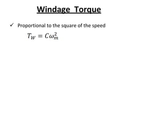
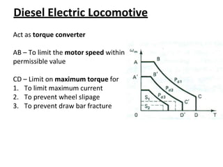
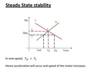
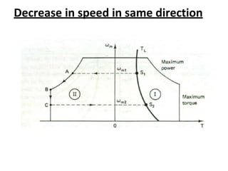
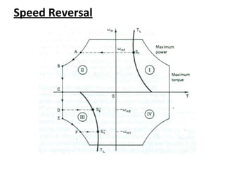
EE8601
SOLID STATE DRIVES
UNIT I
DRIVE CHARACTERISTICS
Dr.P.Subha Karuvelam
Professor (CAS)/EEE
Government College of Engineering
Tirunelveli – 627007.
Electric Drives
• Systems employed for motion control are called
as Drives.
• It may employ any of prime movers such as diesel
or petrol engines, gas or steam turbines, steam
engines, hydraulic motors and electric motors, for
supplying mechanical energy for motion control.
• Drives employing electric motors are called as
Electrical Drives.
Parts Of Electric Drives
Parts of Electric Drives
Power Modulator :
• The power modulator regulates the output power of
the source.
• It controls the power from the source to the motor in
such a manner that motor transmits the speed
torque characteristic required by the load.
• During the transient operations like starting,
braking and speed reversing the excessive current
drawn from the source.
POWER MODULATOR(Cont’d)
This excessive current drawn from the source may overload it
or may cause a voltage drop. Hence the power modulator
restricts the source and motor current
The power modulator converts the energy according to the
requirement of the motor
 e.g. if the source is DC and an induction motor is
used then power modulator convert DC into AC.
 It also selects the mode of operation of the motor, i.e.,
motoring or braking.
CONTROL UNIT
Control Unit :
• Consists of linear and digital integrated circuits and
transistors
• The control unit controls the power modulator which
operates at small voltage and power levels. The
control unit also operates the power modulator as
desired.
• It also generates the commands for the protection of
power modulator and motor. An input command
signal which adjusts the operating point of the drive,
from an input to the control unit.
SENSING UNIT
Sensing Unit :
• It senses the certain drive parameter like motor
current and speed.
• It mainly required either for protection or for closed
loop operation.
ADVANTAGE OF ELECTRIC DRIVES
Advantages of Electrical Drive:
• The electrical drives are available in a wide range of
torque, speed and power.
• They are adaptable to almost
conditions such as explosive
any operating
and radioactive
environment, submerged in liquids, vertical
mounting and so on.
• The electrical drive does not pollute the
environment.
ADVANTAGE OF ELECTRIC
DRIVES(Cont’d)
• It can operate in all four quadrants of speed
torque plane.
• They can be started instantly and can
immediately be fully loaded. i.e., there is no need
to refuel or warm up the motor.
• They have flexible control characteristic and can
be employed to automatically control the drive.
ADVANTAGE OF ELECTRIC
DRIVES(Cont’d)
• Because of the following advantages, the mechanical
energy already available from a non-electrical prime
mover is sometimes first converted into electrical
energy by a generator and back to a mechanical energy
of an electrical motor.
• Electrical link thus provides between the non-electrical
prime mover and the load impact to the drive flexible
control characteristic.
Disadvantage Of Electric Drives
Disadvantages of Electrical Drive:
• The power failure completely disabled the whole of
the system.
• The application of the drive is limited because it
cannot use in a place where the power supply is not
available.
• It can cause noise pollution.
• The initial cost of the system is high.
CLASSIFICATION OF ELECTRIC DRIVES
Generally classified into 3 categories:
• Group drive
• Individual Drive
• Multimotor Drive
Group drive
If several group of mechanisms or machines are organized on
one shaft and driven or actuated by one motor, the system is
called a group drive or shaft drive.
Advantage : Most Economical
Disadvantage :
• Any Fault that occurs in the driving motor renders all the
driving equipment idle.
• Efficiency low because of losses occurring in the energy
transmitting mechanisms (Power loss).
• Not safe to operate. Also Noise level at the working spot
is high.
Individual Drive:
• If a single motor is used to drive or actuate a given
mechanism and it does all the jobs connected with
this load , the drive is called individual drive.
• All the operations connected with operating a lathe
may be performed by a single motor.
• Each motor is driven by its own separated motor
with the help of gears , pulleys etc.
Multi Motor Drive:
• Each operation of the mechanism is taken care of by
a separate drive motor.
• The System contains several individual drives each of
which is used to operate its own mechanism.
• Applications: Complicated metal cutting machine
tools, Paper making industries, rolling machines etc
Multi Motor Drive:
Separate motors are provided for actuating different parts
of the driven mechanism.
Advantage :
• Each Machine is driven by a separated motor it can be
run and stopped as desired.
• Machines not required can be shut down and also
replaced with a minimum of dislocation.
• There is a flexibility in the installation of different
machines.
Multi Motor Drive:
• In the case of motor fault, only its connected machine will
stop where as others will continue working undisturbed.
• Absence of belts and line shafts greatly reduces the risk of a
accidents to the operating personnel.
Disadvantage:
• Initial high cost
Dynamics of motor-load system
• When an electric motor rotates, it is usually
connected to a load which has a rotational or
translational motion.
• The speed of the motor may be different from
that of the load. To analyze the relation
among the drives and loads, the concept
of dynamics of electrical drives is introduced.
Dynamics of motor-load combination
Drive
J = Polar moment of inertia of motor load (kg-m2)
m = Instantaneous angular velocity (rad/sec)
T = Instantaneous value of developed motor torque (N-m)
T1 = Instantaneous value of load torque referred to motor
shaft (N-m)
Dynamics of motor-load System
• Now, from the fundamental torque equation
• For the drive with constant inertia
Motor Torque = Load Torque + Dynamic Torque
Dynamics of motor-load System
• Dynamic torque J(dωm/dt) present during the
transient operations.
• During Acceleration
• During Deceleration
COMPONENTS OF LOAD TORQUE
Divided into 3 components
1. Friction Torque -
2. Windage Torque –
3. Torque required to do useful mechanical
work.
COMPONENTS OF LOAD TORQUE
1. Friction Torque
Present at the motor shaft and also in various
parts of the load. TF is the equivalent value of
various friction torques referred to the motor
shaft.
2. Windage Torque (TW):
When motor runs, wind generates a torque
opposing the motion is known as windage
torque.
COMPONENTS OF LOAD TORQUE
3. Torque required to do useful
mechanical work.
• Nature of this torque depends upon
particular application.
• It may be some function of speed, it may
be time invariant or time variant, its
nature may also change with the load’s
mode ofoperation.
Friction Torque
3 Components are
1. Static Friction
Friction at zero speed is
Stiction or static friction
2. Viscous Friction
Varies linearly with speed
B – Viscous friction coefficient
3. Coulomb Friction
Independent of spped
Windage Torque
 Proportional to the square of the speed
COMPONENTS OF LOAD TORQUE
For finite speed,
Common Load Torques
1. Fan and Centrifugal pumps
2. Traction
3. Coiler Drives
4. Diesel Electric Locomotive
5. Excavators
6. Hoist
CONSTANT TORQUE AND CONSTANT
POWER OPERATION
Fan and Centrifugal Loads
Windage torque predominates
Traction Drives
Comprises of
 Windage torque
 Viscous friction
 Coulomb friction
 Stiction
Coiler Drives
Motor will operate at Constant
Power
 Steel Mill
 Paper Mill
 Plastic Mill
 To maintain the tension of the
steel, paper, plastic strip the
motor operated in Constant
power mode
Diesel Electric Locomotive
Act as torque converter
AB – To limit the motor speed within
permissible value
CD – Limit on maximum torque for
1. To limit maximum current
2. To prevent wheel slipage
3. To prevent draw bar fracture
Excavators
When load torque is high, the
motor will simply stop.
To prevent the mechanical damage
to the excavator
Hoist
For low speed hoist, load
torque is mainly due to
gravitational force
Gravity is constant and
independent of speed
For high speed hoist,
viscous friction and
windage plays active role
TORQUE-SPEED SIGN CONVENTON
Classification of load torques
Various load torques can be classified
into broad categories.
• Active load torques
• Passive load torques
Active Load
Load torques which has the potential to drive the
motor under equilibrium conditions are called active
load torques
Retain their sign if the drive rotation is changed
Torque due to gravity, tension, compression and tension
due to elastic body.
Passive loads
Always oppose the motion and change their
direction on the reversal of motion
Friction, Cutting, drilling etc
Steady and Transient state
stability of Electric Drive
• The drive is said to be in equilibrium if
• Stable system:
If the system can able restore the stable speed
after a small disturbance in supply, load or
part of the drive
Steady and Transient state stability of
Electric Drive
• Changes from the state of equilibrium takes
place slowly and the effect of either the
inertia or the inductance is insignificant –
Steady state stability.
Sudden and fast changes from the equilibrium
state so effect of both inertia and inductance
can not be neglected- Dynamic or transient
stability.
Steady and Transient state stability of
Electric Drive
• Criteria for steady state stability:-
• At time ‘t’
Steady State Stability
Steady State stability
In new speed,
Hence acceleration will occur and speed of the motor increases.
Steady State stability
In new speed,
Hence deceleration will occur and speed of the motor decreases.
FOUR QUADRANT OPERATION
Modes of Operation
Speed – Torque Curves with different
speed settings
Modes of Operation
1. Increase in speed in same direction
2. Decrease in speed in same direction
3. Speed Reversal
Increase in speed in same direction
Decrease in speed in same direction
Speed Reversal
Speed Reversal
Choice or selection of drives
Steady State Operating conditions requirements:
Nature of speed torque characteristics, speed regulation, speed
range, efficiency, duty cycle, quadrants of operation, speed
fluctuations if any, ratings etc
Transient operation requirements:
Values of acceleration and deceleration, starting, braking and reversing
performance.
Requirements related to the source:
Types of source and its capacity, magnitude of voltage, voltage
fluctuations, power factor, harmonics and their effect on other loads,
ability to accept regenerative power
Capital and running cost, maintenance needs life.
 Space and weight restriction if any.
Environment and location.
Reliability.

Unit I Introduction to Solid State Drives.pptx

  • 1.
  • 2.
    UNIT I DRIVE CHARACTERISTICS Dr.P.SubhaKaruvelam Professor (CAS)/EEE Government College of Engineering Tirunelveli – 627007.
  • 3.
    Electric Drives • Systemsemployed for motion control are called as Drives. • It may employ any of prime movers such as diesel or petrol engines, gas or steam turbines, steam engines, hydraulic motors and electric motors, for supplying mechanical energy for motion control. • Drives employing electric motors are called as Electrical Drives.
  • 4.
  • 5.
    Parts of ElectricDrives Power Modulator : • The power modulator regulates the output power of the source. • It controls the power from the source to the motor in such a manner that motor transmits the speed torque characteristic required by the load. • During the transient operations like starting, braking and speed reversing the excessive current drawn from the source.
  • 6.
    POWER MODULATOR(Cont’d) This excessivecurrent drawn from the source may overload it or may cause a voltage drop. Hence the power modulator restricts the source and motor current The power modulator converts the energy according to the requirement of the motor  e.g. if the source is DC and an induction motor is used then power modulator convert DC into AC.  It also selects the mode of operation of the motor, i.e., motoring or braking.
  • 7.
    CONTROL UNIT Control Unit: • Consists of linear and digital integrated circuits and transistors • The control unit controls the power modulator which operates at small voltage and power levels. The control unit also operates the power modulator as desired. • It also generates the commands for the protection of power modulator and motor. An input command signal which adjusts the operating point of the drive, from an input to the control unit.
  • 8.
    SENSING UNIT Sensing Unit: • It senses the certain drive parameter like motor current and speed. • It mainly required either for protection or for closed loop operation.
  • 9.
    ADVANTAGE OF ELECTRICDRIVES Advantages of Electrical Drive: • The electrical drives are available in a wide range of torque, speed and power. • They are adaptable to almost conditions such as explosive any operating and radioactive environment, submerged in liquids, vertical mounting and so on. • The electrical drive does not pollute the environment.
  • 10.
    ADVANTAGE OF ELECTRIC DRIVES(Cont’d) •It can operate in all four quadrants of speed torque plane. • They can be started instantly and can immediately be fully loaded. i.e., there is no need to refuel or warm up the motor. • They have flexible control characteristic and can be employed to automatically control the drive.
  • 11.
    ADVANTAGE OF ELECTRIC DRIVES(Cont’d) •Because of the following advantages, the mechanical energy already available from a non-electrical prime mover is sometimes first converted into electrical energy by a generator and back to a mechanical energy of an electrical motor. • Electrical link thus provides between the non-electrical prime mover and the load impact to the drive flexible control characteristic.
  • 12.
    Disadvantage Of ElectricDrives Disadvantages of Electrical Drive: • The power failure completely disabled the whole of the system. • The application of the drive is limited because it cannot use in a place where the power supply is not available. • It can cause noise pollution. • The initial cost of the system is high.
  • 13.
    CLASSIFICATION OF ELECTRICDRIVES Generally classified into 3 categories: • Group drive • Individual Drive • Multimotor Drive
  • 14.
    Group drive If severalgroup of mechanisms or machines are organized on one shaft and driven or actuated by one motor, the system is called a group drive or shaft drive. Advantage : Most Economical Disadvantage : • Any Fault that occurs in the driving motor renders all the driving equipment idle. • Efficiency low because of losses occurring in the energy transmitting mechanisms (Power loss). • Not safe to operate. Also Noise level at the working spot is high.
  • 15.
    Individual Drive: • Ifa single motor is used to drive or actuate a given mechanism and it does all the jobs connected with this load , the drive is called individual drive. • All the operations connected with operating a lathe may be performed by a single motor. • Each motor is driven by its own separated motor with the help of gears , pulleys etc.
  • 16.
    Multi Motor Drive: •Each operation of the mechanism is taken care of by a separate drive motor. • The System contains several individual drives each of which is used to operate its own mechanism. • Applications: Complicated metal cutting machine tools, Paper making industries, rolling machines etc
  • 17.
    Multi Motor Drive: Separatemotors are provided for actuating different parts of the driven mechanism. Advantage : • Each Machine is driven by a separated motor it can be run and stopped as desired. • Machines not required can be shut down and also replaced with a minimum of dislocation. • There is a flexibility in the installation of different machines.
  • 18.
    Multi Motor Drive: •In the case of motor fault, only its connected machine will stop where as others will continue working undisturbed. • Absence of belts and line shafts greatly reduces the risk of a accidents to the operating personnel. Disadvantage: • Initial high cost
  • 19.
    Dynamics of motor-loadsystem • When an electric motor rotates, it is usually connected to a load which has a rotational or translational motion. • The speed of the motor may be different from that of the load. To analyze the relation among the drives and loads, the concept of dynamics of electrical drives is introduced.
  • 20.
    Dynamics of motor-loadcombination Drive J = Polar moment of inertia of motor load (kg-m2) m = Instantaneous angular velocity (rad/sec) T = Instantaneous value of developed motor torque (N-m) T1 = Instantaneous value of load torque referred to motor shaft (N-m)
  • 21.
    Dynamics of motor-loadSystem • Now, from the fundamental torque equation • For the drive with constant inertia Motor Torque = Load Torque + Dynamic Torque
  • 22.
    Dynamics of motor-loadSystem • Dynamic torque J(dωm/dt) present during the transient operations. • During Acceleration • During Deceleration
  • 23.
    COMPONENTS OF LOADTORQUE Divided into 3 components 1. Friction Torque - 2. Windage Torque – 3. Torque required to do useful mechanical work.
  • 24.
    COMPONENTS OF LOADTORQUE 1. Friction Torque Present at the motor shaft and also in various parts of the load. TF is the equivalent value of various friction torques referred to the motor shaft. 2. Windage Torque (TW): When motor runs, wind generates a torque opposing the motion is known as windage torque.
  • 25.
    COMPONENTS OF LOADTORQUE 3. Torque required to do useful mechanical work. • Nature of this torque depends upon particular application. • It may be some function of speed, it may be time invariant or time variant, its nature may also change with the load’s mode ofoperation.
  • 26.
    Friction Torque 3 Componentsare 1. Static Friction Friction at zero speed is Stiction or static friction 2. Viscous Friction Varies linearly with speed B – Viscous friction coefficient 3. Coulomb Friction Independent of spped
  • 27.
    Windage Torque  Proportionalto the square of the speed
  • 28.
    COMPONENTS OF LOADTORQUE For finite speed,
  • 29.
    Common Load Torques 1.Fan and Centrifugal pumps 2. Traction 3. Coiler Drives 4. Diesel Electric Locomotive 5. Excavators 6. Hoist
  • 30.
    CONSTANT TORQUE ANDCONSTANT POWER OPERATION
  • 31.
    Fan and CentrifugalLoads Windage torque predominates
  • 32.
    Traction Drives Comprises of Windage torque  Viscous friction  Coulomb friction  Stiction
  • 33.
    Coiler Drives Motor willoperate at Constant Power  Steel Mill  Paper Mill  Plastic Mill  To maintain the tension of the steel, paper, plastic strip the motor operated in Constant power mode
  • 34.
    Diesel Electric Locomotive Actas torque converter AB – To limit the motor speed within permissible value CD – Limit on maximum torque for 1. To limit maximum current 2. To prevent wheel slipage 3. To prevent draw bar fracture
  • 35.
    Excavators When load torqueis high, the motor will simply stop. To prevent the mechanical damage to the excavator
  • 36.
    Hoist For low speedhoist, load torque is mainly due to gravitational force Gravity is constant and independent of speed For high speed hoist, viscous friction and windage plays active role
  • 37.
  • 38.
    Classification of loadtorques Various load torques can be classified into broad categories. • Active load torques • Passive load torques
  • 39.
    Active Load Load torqueswhich has the potential to drive the motor under equilibrium conditions are called active load torques Retain their sign if the drive rotation is changed Torque due to gravity, tension, compression and tension due to elastic body.
  • 40.
    Passive loads Always opposethe motion and change their direction on the reversal of motion Friction, Cutting, drilling etc
  • 41.
    Steady and Transientstate stability of Electric Drive • The drive is said to be in equilibrium if • Stable system: If the system can able restore the stable speed after a small disturbance in supply, load or part of the drive
  • 42.
    Steady and Transientstate stability of Electric Drive • Changes from the state of equilibrium takes place slowly and the effect of either the inertia or the inductance is insignificant – Steady state stability. Sudden and fast changes from the equilibrium state so effect of both inertia and inductance can not be neglected- Dynamic or transient stability.
  • 43.
    Steady and Transientstate stability of Electric Drive • Criteria for steady state stability:- • At time ‘t’
  • 44.
  • 45.
  • 46.
    Steady State stability Innew speed, Hence acceleration will occur and speed of the motor increases.
  • 47.
    Steady State stability Innew speed, Hence deceleration will occur and speed of the motor decreases.
  • 48.
  • 49.
  • 50.
  • 51.
    Speed – TorqueCurves with different speed settings
  • 52.
    Modes of Operation 1.Increase in speed in same direction 2. Decrease in speed in same direction 3. Speed Reversal
  • 53.
    Increase in speedin same direction
  • 54.
    Decrease in speedin same direction
  • 55.
  • 56.
  • 57.
    Choice or selectionof drives Steady State Operating conditions requirements: Nature of speed torque characteristics, speed regulation, speed range, efficiency, duty cycle, quadrants of operation, speed fluctuations if any, ratings etc Transient operation requirements: Values of acceleration and deceleration, starting, braking and reversing performance. Requirements related to the source: Types of source and its capacity, magnitude of voltage, voltage fluctuations, power factor, harmonics and their effect on other loads, ability to accept regenerative power Capital and running cost, maintenance needs life.  Space and weight restriction if any. Environment and location. Reliability.