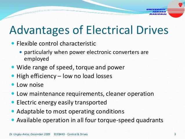
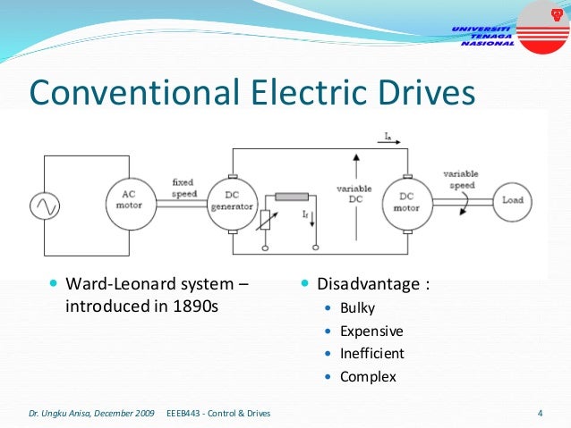
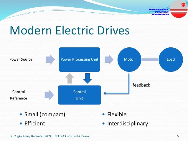
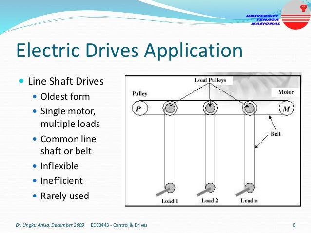
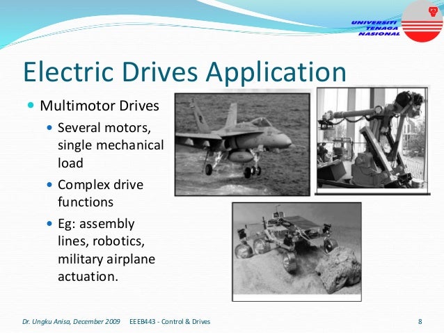
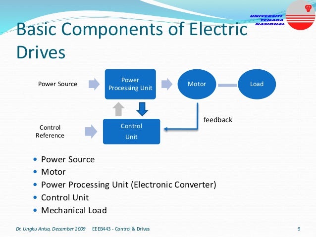
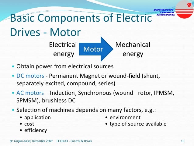
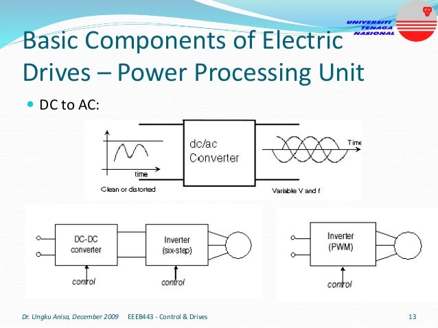
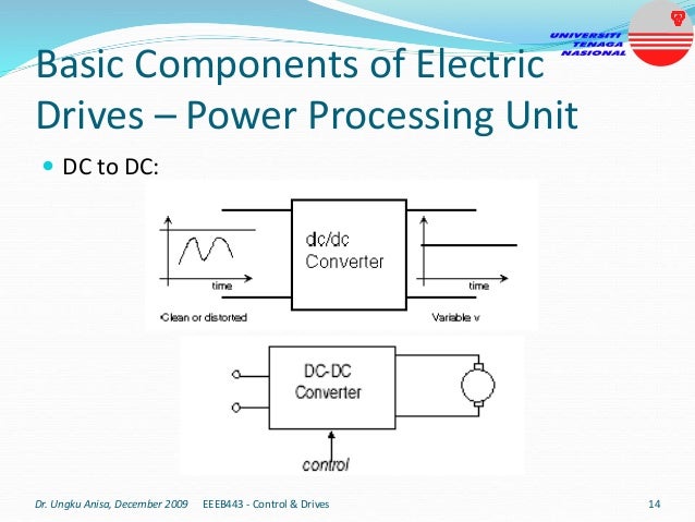
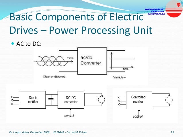
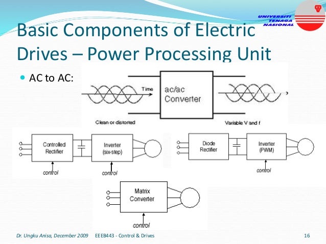
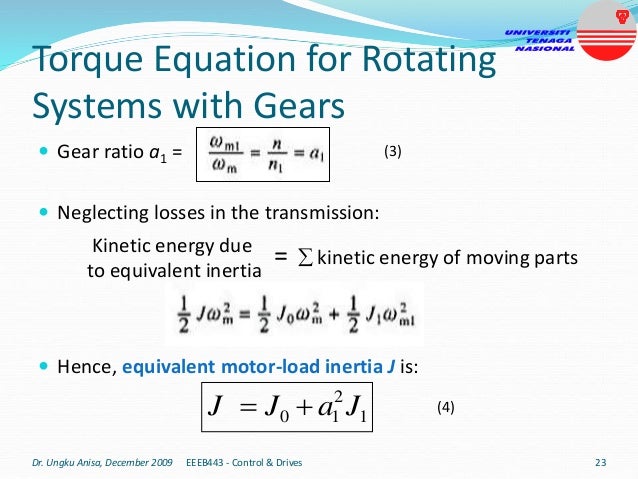
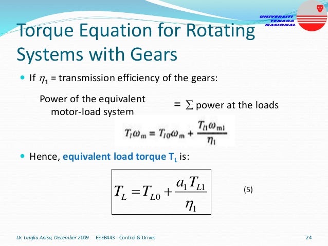
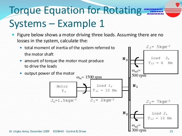
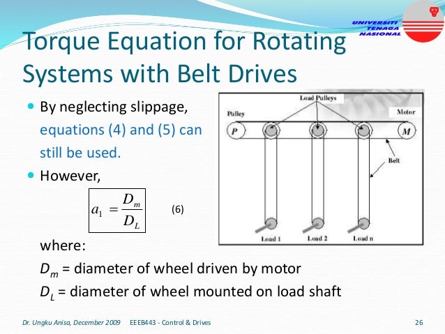
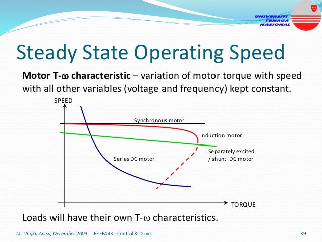
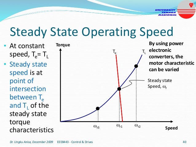
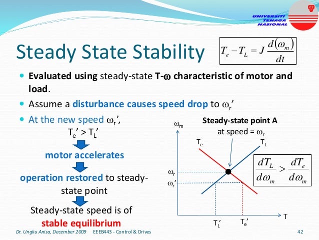
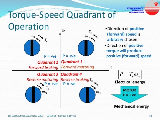
This document provides an introduction to electrical drives. It defines electrical drives as systems that employ electric motors as prime movers for motion control. The advantages of electrical drives include flexible control, wide speed and torque ranges, high efficiency, and operation in all four torque-speed quadrants. Modern electric drives are more compact, efficient and flexible compared to conventional drives due to use of power electronics. Electric drives find applications in line shaft drives, single motor-single load drives, and multimotor drives. The basic components of an electric drive system are the power source, motor, power processing unit, control unit, and mechanical load.
1. Introduction to Electrical Drives
By
Dr. Ungku Anisa Ungku Amirulddin
Department of Electrical Power Engineering
College of Engineering
Dr. Ungku Anisa, December 2009 1
EEEB443 - Control & Drives
2. Definition of Electrical Drives
Drives – system employed
for motion control
Motion control requires
prime movers
Electrical Drives – Drives
that employ Electric
Motors as prime movers
Electrical Drives -> Electric
Motor as Prime Mover
Prime Mover
Drives -> Motion Control
Dr. Ungku Anisa, December 2009 2
EEEB443 - Control & Drives
3. Advantages of Electrical Drives
Flexible control characteristic
particularly when power electronic converters are
employed
Wide range of speed, torque and power
High efficiency – low no load losses
Low noise
Low maintenance requirements, cleaner operation
Electric energy easily transported
Adaptable to most operating conditions
Available operation in all four torque-speed quadrants
Dr. Ungku Anisa, December 2009 EEEB443 - Control & Drives 3
4. Conventional Electric Drives
Ward-Leonard system –
introduced in 1890s
Disadvantage :
Bulky
Expensive
Inefficient
Complex
Dr. Ungku Anisa, December 2009 4
EEEB443 - Control & Drives
5. Modern Electric Drives
Small (compact)
Efficient
Flexible
Interdisciplinary
Power Source Power Processing Unit Motor Load
Control
Reference
Control
Unit
feedback
Dr. Ungku Anisa, December 2009 5
EEEB443 - Control & Drives
6. Electric Drives Application
Line Shaft Drives
Oldest form
Single motor,
multiple loads
Common line
shaft or belt
Inflexible
Inefficient
Rarely used
Dr. Ungku Anisa, December 2009 6
EEEB443 - Control & Drives
7. Electric Drives Application
Single-Motor, Single-
Load Drives
Most common
Eg: electric saws,
drills, fans, washers,
blenders, disk-
drives, electric cars.
Dr. Ungku Anisa, December 2009 7
EEEB443 - Control & Drives
8. Electric Drives Application
Multimotor Drives
Several motors,
single mechanical
load
Complex drive
functions
Eg: assembly
lines, robotics,
military airplane
actuation.
Dr. Ungku Anisa, December 2009 8
EEEB443 - Control & Drives
9. Basic Components of Electric
Drives
Power Source
Motor
Power Processing Unit (Electronic Converter)
Control Unit
Mechanical Load
Power Source
Power
Processing Unit
Motor Load
Control
Reference
Control
Unit
feedback
Dr. Ungku Anisa, December 2009 9
EEEB443 - Control & Drives
10. Basic Components of Electric
Drives - Motor
• Obtain power from electrical sources
• DC motors - Permanent Magnet or wound-field (shunt,
separately excited, compound, series)
• AC motors – Induction, Synchronous (wound –rotor, IPMSM,
SPMSM), brushless DC
• Selection of machines depends on many factors, e.g.:
Dr. Ungku Anisa, December 2009 10
EEEB443 - Control & Drives
Electrical
energy
Mechanical
energy
Motor
• application
• cost
• efficiency
• environment
• type of source available
11. Basic Components of Electric
Drives – Power Source
• Provides energy to electric motors
• Regulated (e.g: utility) or Unregulated (e.g. : renewable
energy)
• Unregulated power sources must be regulated for high
efficiency – use power electronic converters
• DC source
• batteries
• fuel cell
• photovoltaic
• AC source
• single- or three- phase utility
• wind generator
Dr. Ungku Anisa, December 2009 11
EEEB443 - Control & Drives
12. Basic Components of Electric
Drives – Power Processing Unit
• Provides a regulated power supply to motor
• Enables motor operation in reverse, braking and variable
speeds
• Combination of power electronic converters
Controlled rectifiers, inverters –treated as ‘black boxes’ with
certain transfer function
More efficient – ideally no losses occur
Flexible - voltage and current easily shaped through
switching control
Compact
Several conversions possible: AC-DC , DC-DC, DC-AC, AC-AC
Dr. Ungku Anisa, December 2009 12
EEEB443 - Control & Drives
13. Basic Components of Electric
Drives – Power Processing Unit
DC to AC:
Dr. Ungku Anisa, December 2009 13
EEEB443 - Control & Drives
14. Basic Components of Electric
Drives – Power Processing Unit
DC to DC:
Dr. Ungku Anisa, December 2009 14
EEEB443 - Control & Drives
15. Basic Components of Electric
Drives – Power Processing Unit
AC to DC:
Dr. Ungku Anisa, December 2009 15
EEEB443 - Control & Drives
16. Basic Components of Electric
Drives – Power Processing Unit
AC to AC:
Dr. Ungku Anisa, December 2009 16
EEEB443 - Control & Drives
17. Basic Components of Electric
Drives – Control Unit
• Supervise operation
• Enhance overall performance and stability
• Complexity depends on performance requirement
• Analog Control – noisy, inflexible, ideally infinite bandwidth
• Digital Control – immune to noise, configurable, smaller
bandwidth (depends on sampling frequency)
• DSP/microprocessor – flexible, lower bandwidth, real-time
• DSPs perform faster operation than microprocessors
(multiplication in single cycle), complex estimations and
observers easily implemented
Dr. Ungku Anisa, December 2009 17
EEEB443 - Control & Drives
18. Basic Components of Electric
Drives – Component Selection
• Several factors affecting drive selection:
• Steady-state operation requirements
• nature of torque-speed profile, speed regulation, speed range,
efficiency, quadrants of operations, converter ratings
• Transient operation requirements
• values of acceleration and deceleration, starting, braking and reversing
performance
• Power source requirements
• Type, capacity, voltage magnitude, voltage fluctuations, power factor,
harmonics and its effect on loads, ability to accept regenerated power
• Capital & running costs
• Space and weight restrictions
• Environment and location
• Efficiency and reliability
Dr. Ungku Anisa, December 2009 18
EEEB443 - Control & Drives
19. DC or AC Drives?
DC Drives
AC Drives
(particularly Induction Motor)
Motor • requires maintenance
• heavy, expensive
• limited speed (due to
mechanical construction)
• less maintenance
• light, cheaper
• high speeds achievable (squirrel-
cage IM)
• robust
Control Unit Simple & cheap control even
for high performance drives
• decoupled torque and flux control
• Possible implementation using
single analog circuit
Depends on required drive
performance
• complexity & costs increase with
performance
• DSPs or fast processors required in high
performance drives
Performance Fast torque and flux control Scalar control – satisfactory in some
applications
Vector control – similar to DC drives
Dr. Ungku Anisa, December 2009 19
EEEB443 - Control & Drives
20. Torque Equation for Rotating
Systems
Motor drives a load through a transmission system (eg. gears,
V-belts, crankshaft and pulleys)
Load may rotate or undergo translational motion
Load speed may be different from motor speed
Can also have multiple loads each having different speeds,
some may rotate and some have translational motion
Dr. Ungku Anisa, December 2009 EEEB443 - Control & Drives 20
Motor Load
Te , m TL
Represent motor-load
system as equivalent
rotational system
21. Torque Equation for Rotating
Systems
• First order differential equation for angular frequency (or velocity)
• Second order differential equation for angle (or position)
2
2
dt
d
J
dt
d
J
T
T m
L
e
With constant inertia J,
dt
J
d
T
T m
L
e
Te , m
TL
Dr. Ungku Anisa, December 2009 21
EEEB443 - Control & Drives
Torque equation for equivalent motor-load system:
where:
J = inertia of equivalent motor-load system, kgm2
m = angular velocity of motor shaft, rads-1
Te = motor torque, Nm
TL = load torque referred to motor shaft, Nm
(1)
(2)
22. Torque Equation for Rotating
Systems with Gears
Low speed
applications use
gears to utilize high
speed motors
Motor drives two
loads:
Load 1 coupled
directly to motor
shaft
Load 2 coupled via
gear with n and n1
teeth
Need to obtain
equivalent motor-
load system
Dr. Ungku Anisa, December 2009 EEEB443 - Control & Drives 22
Motor
Te
Load 1,
TL0
Load 2,
TL1
J0
J1
m
m
m1
n
n1
TL0
TL1
Motor
Te
J
Equivalent
Load , TL
m
TL
23. Torque Equation for Rotating
Systems with Gears
Gear ratio a1 =
Neglecting losses in the transmission:
Hence, equivalent motor-load inertia J is:
Dr. Ungku Anisa, December 2009 EEEB443 - Control & Drives 23
Kinetic energy due
to equivalent inertia
= kinetic energy of moving parts
1
2
1
0 J
a
J
J
(3)
(4)
24. Torque Equation for Rotating
Systems with Gears
If 1 = transmission efficiency of the gears:
Hence, equivalent load torque TL is:
Dr. Ungku Anisa, December 2009 EEEB443 - Control & Drives 24
Power of the equivalent
motor-load system
= power at the loads
1
1
1
0
L
L
L
T
a
T
T
(5)
25. Torque Equation for Rotating
Systems – Example 1
Figure below shows a motor driving three loads. Assuming there are no
losses in the system, calculate the:
total moment of inertia of the system referred to
the motor shaft
amount of torque the motor must produce
to drive the loads
output power of the motor
Dr. Ungku Anisa, December 2009 EEEB443 - Control & Drives 25
Motor
T e
Load 1,
T L1 = 10 Nm
Load 2,
T L2 = 10 Nm
Jm=1.5kgm-2
m 1500 rpm
N1
N2
N3
Load 3,
T L3 = 6 Nm
J1 = 2kgm-2
J2= 7kgm-2
J3= 5kgm-2
m3
500 rpm
m2
300 rpm
26. Torque Equation for Rotating
Systems with Belt Drives
By neglecting slippage,
equations (4) and (5) can
still be used.
However,
where:
Dm = diameter of wheel driven by motor
DL = diameter of wheel mounted on load shaft
Dr. Ungku Anisa, December 2009 EEEB443 - Control & Drives 26
L
m
D
D
a
1 (6)
27. Torque Equation for Rotating
Systems with Translational Motion
Motor drives two
loads:
Load 1 coupled
directly to motor
shaft
Load 2 coupled via
transmission
system converting
rotational to linear
motion
Need to obtain
equivalent motor-
load system
Dr. Ungku Anisa, December 2009 EEEB443 - Control & Drives 27
Motor
Te
J
Equivalent
Load , TL
m
TL
28. Torque Equation for Rotating
Systems with Translational Motion
Neglecting losses in the transmission:
Hence, equivalent motor-load inertia J is:
Dr. Ungku Anisa, December 2009 EEEB443 - Control & Drives 28
Kinetic energy due
to equivalent inertia
= kinetic energy of moving parts
2
1
1
0
m
v
M
J
J
(7)
29. If 1 = transmission efficiency of the transmission system:
Hence, equivalent load torque TL is:
Torque Equation for Rotating
Systems with Translational Motion
Dr. Ungku Anisa, December 2009 EEEB443 - Control & Drives 29
Power of the equivalent
motor-load system
= power at the loads and motor
m
L
L
v
F
T
T
1
1
1
0
(8)
30. Relation between Translational and
Rotational Motions
The relationship between the torques and linear forces are:
Relationship between linear and angular velocity:
Hence, assuming the mass M is constant:
Dr. Ungku Anisa, December 2009 EEEB443 - Control & Drives 30
1
1 rF
T m
m rF
T
r
v
dt
dv
M
F
Fm
1
dt
d
Mr
T
Tm
2
1
31. Torque Equation for Rotating
Systems – Example 2
An example of a hoist drive employing gears is shown below.
The system can be represented by an equivalent system shown
on the right. Write down the equation for the:
Equivalent system moment of inertia
Equivalent system load torque
Dr. Ungku Anisa, December 2009 EEEB443 - Control & Drives 31
Hoist drive
Equivalent system
32. Torque Equation for Rotating
Systems – Example 3
If the motor is rated at 19kW, is the motor sufficient to drive
the two loads?
The translational motion load now has to lift a weight of 1200
kg at the same speed of 1.5m/s. Is the motor still capable to
drive both loads at the same motor speed of 1420 rpm?
Dr. Ungku Anisa, December 2009 EEEB443 - Control & Drives 32
33. Components of Load Torque
• Load torque can be divided into:
• Friction torque – present at motor shaft and in various
parts of load.
• Viscous friction torque Tv – varies linearly with speed (Tv m).
Exists in lubricated bearings due to laminar flow of lubricant
• Coulomb friction torque TC – independent of speed. Exists in
bearings, gears coupling and brakes.
• Windage torque Tw – exists due to turbulent flow of air or
liquid.
• Varies proportional to speed squared (Tw m
2).
• Mechanical Load Torque TL - torque to do useful
mechanical work.
Dr. Ungku Anisa, December 2009 33
EEEB443 - Control & Drives
34. Mechanical Load Torque
• Torque to do useful mechanical work TL – depends on
application.
• Load torque is function of speed
• where k = integer or fraction
• Mechanical power of load:
• and
k
m
L
T
m
L
T
P
m
m n
60
2
Angular speed
in rad/s
Speed
in rpm
Dr. Ungku Anisa, December 2009 34
EEEB443 - Control & Drives
36. Mechanical Load Torque
Torque independent
of speed , k = 0
Hoist
Elevator
Pumping of water
or gas against
constant pressure
Dr. Ungku Anisa, December 2009 36
EEEB443 - Control & Drives
37. Mechanical Load Torque
Torque proportional
to square of speed ,
k = 2
Fans
Centrifugal pumps
Propellers
Dr. Ungku Anisa, December 2009 37
EEEB443 - Control & Drives
38. Mechanical Load Torque
Torque inversely
proportional to
speed , k = -1
Milling machines
Electric drill
Electric saw
Dr. Ungku Anisa, December 2009 38
EEEB443 - Control & Drives
39. Motor T- characteristic – variation of motor torque with speed
with all other variables (voltage and frequency) kept constant.
Loads will have their own T- characteristics.
Steady State Operating Speed
Synchronous motor
Induction motor
Separately excited
/ shunt DC motor
Series DC motor
SPEED
TORQUE
Dr. Ungku Anisa, December 2009 39
EEEB443 - Control & Drives
40. Steady State Operating Speed
• At constant
speed, Te= TL
• Steady state
speed is at
point of
intersection
between Te
and TL of the
steady state
torque
characteristics
TL
Te
Steady state
Speed, r
Torque
Speed
r2
r3
r1
Dr. Ungku Anisa, December 2009 40
EEEB443 - Control & Drives
By using power
electronic
converters, the
motor characteristic
can be varied
41. Steady State Stability
Drives operate at steady-state speed (when Te = TL) only if the
speed is of stable equilibrium.
A disturbance in any part of drive causes system speed to
depart from steady-state point.
Steady-state speed is of stable equilibrium if:
system will return to stable equilibrium speed when
subjected to a disturbance
Steady-state stability evaluated using steady-state T-
characteristic of motor and load.
Condition for stable equilibrium:
Dr. Ungku Anisa, December 2009 EEEB443 - Control & Drives 41
m
e
m
L
d
dT
d
dT
(9)
42. Steady State Stability
Evaluated using steady-state T- characteristic of motor and
load.
Assume a disturbance causes speed drop to r’
At the new speed r’,
Dr. Ungku Anisa, December 2009 EEEB443 - Control & Drives 42
Te TL
Steady-state point A
at speed = r
r
r’
Te’
TL’
Te’ > TL’
motor accelerates
operation restored to steady-
state point
m
T
Steady-state speed is of
stable equilibrium
m
e
m
L
d
dT
d
dT
dt
d
J
T
T m
L
e
43. Steady State Stability
Let’s look at a different condition!
Assume a disturbance causes speed drop to r’
At the new speed r’,
Dr. Ungku Anisa, December 2009 EEEB443 - Control & Drives 43
Te
TL
Steady-state point B
at speed = r
r
r’
TL’
Te’
Te’ < TL’
motor decelerates
operation point moves away
from steady-state point
m
T
Point B is at UNSTABLE
equilibrium
m
e
m
L
d
dT
d
dT
dt
d
J
T
T m
L
e
44. Torque-Speed Quadrant of
Operation
m
Te
Te
m
Te
m
Te
m
T
•Direction of positive
(forward) speed is
arbitrary chosen
•Direction of positive
torque will produce
positive (forward) speed
Quadrant 1
Forward motoring
Quadrant 2
Forward braking
Quadrant 3
Reverse motoring
Quadrant 4
Reverse braking
Dr. Ungku Anisa, December 2009 44
EEEB443 - Control & Drives
P = +ve
P = -ve
P = -ve
P = +ve
m
e
T
P
Electrical energy
Mechanical energy
MOTOR
P = + ve
45. References
El-Sharkawi, M. A., Fundamentals of Electric Drives,
Brooks/Cole Publishing Company, California, 2000.
Dubey, G.K., Fundamentals of Electric Drives, 2nd ed., Alpha
Science Int. Ltd., UK, 2001.
Krishnan, R., Electric Motor Drives: Modelling, Analysis and
Control, Prentice-Hall, New Jersey, 2001.
Nik Idris, N. R., Short Course Notes on Electrical Drives,
UNITEN/UTM, 2008.
Ahmad Azli, N., Short Course Notes on Electrical Drives,
UNITEN/UTM, 2008.
Dr. Ungku Anisa, December 2009 45
EEEB443 - Control & Drives