The document provides an overview of digital fundamentals, including:
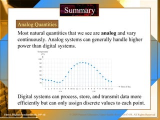
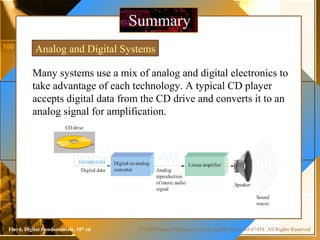
- Analog vs. digital systems and signals
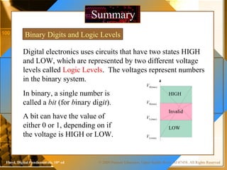
- Binary digits and logic levels in digital electronics
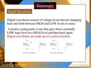
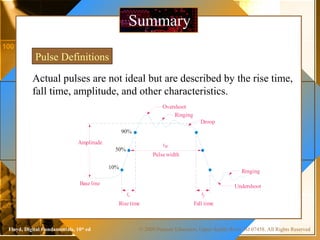
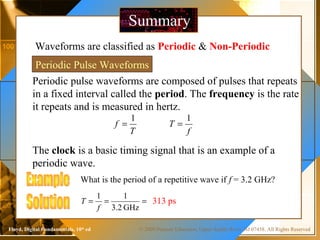
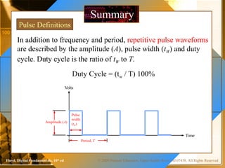
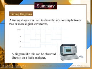
- Characteristics of digital waveforms like pulses and periodic signals
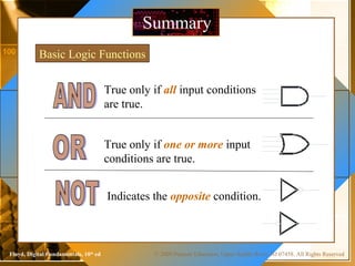
- Basic logic functions like AND, OR, and NOT
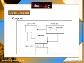
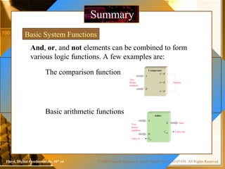
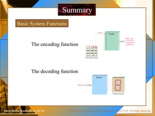
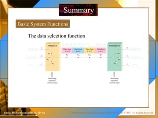
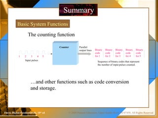
- Common digital components and functions like counters, encoders, multiplexers
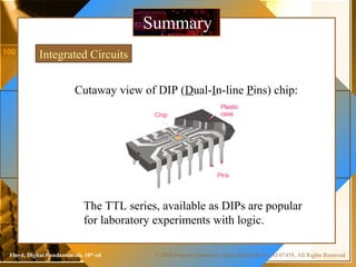
- Integrated circuits and chip packaging